Page is loading ...

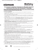
This Restraining Device Must Always Be
Connected When the Appliance Is in Service
The restraining device should be disconnected for move m e n t ,
such as, servicing or cleaning, o n ly after gas has been shut
off and the connector has been disconnected!
Reconnect restraining cable b e fo r e reconnecting the gas
connector and moving back to its original position.
Installation Instructions for
RESTRAINING DEVICE
(For Use with Castered Appliances)
Restraining Device Required per the Following Standards:
ANSI Z21.69/CSA 6.16 Gas Connectors for Moveable Gas Appliances
ANSI Z21.41/CSA 6.9 Quick Disconnect Devices
ANSI Z83.11/CGA 1.8 Commercial Gas Ranges
ANSI Z83.12/CGA 1.9 Commercial Gas Ovens
ANSI Z83.13 Commercial Gas Fryers
ANSI Z223.1/NFPA 54 National Fuel Gas Code Section 5.5.1.e
CSA - B149.1 Natural Gas and Propane Installation Code
Please refer to installation instructions tag on every connector for detailed
information, as specified in ANSI Z21.69/CSA 6.16
Note: The gas connector must be installed in accordance with the National Fuel
Gas Code (ANSI Z223.1/NFPA 54) and any State or Local Code requirements.
Dormont Manufacturing Company makes no warranty, representation or
condition of any kind, express or implied (including any warranty of merchantabili-
ty or of fitness) and none shall be implied by law. Dormont shall not be liable for
incidental or consequential damages.
Call 1-800-DORMONT (367-6668) for additional information
1 . R e s t r aining Device should be installed parallel (in line) with the gas
appliance connector.
2 . Attach the staple bra c ket (C) to a stud in the wall, using the four 1'' #10
s c r e ws (D) and the plastic anchors (E), if needed.
3 . Locate a stru c t u r al area (frame) on the rear side of the equipment that is in
line with the wall attachment. Drill a small hole 1/4'' (per manu f acturers’
recommendation). Please use caution when drilling hole, so that intern a l
components are not damaged.
4 . Thread the hex nut (G) and slide one washer (I) onto the eye-bolt (F).
Slide the eye-bolt through the drilled hole and place a washer (I) and the
nylon lock nut (H) onto the eye-bolt on the inside frame of the equipment and
tighten securely.
5 . Attach one of the spring-loaded hooks (B) to the mounted bra c ket on the wa l l
(Step 2) and the other to the eye-bolt (Steps 3 and 4).
N o t e : For adjustable restraining dev i c e s , the cable is manu factured to be
s h o r ter than the length of the gas connector.
6015 Enterprise Drive, Export, PA 15632
724-733-4800 • FAX: 724-733-4808
w w w . d o r m o n t . c o m
D
1'' #10 Screws
(4)
E
Plastic Anchors
(4)
H
1/4'' Nylon Lock Nut
G
1/4'' Hex Nut
I
1/4'' x 1 1/4''
Washers
(2)
C
Staple Bracket
B
Spring Loaded Hook
A
Restraining
Cable
with Two
Snap Hooks
B
Spring Loaded Hook
F
Eye-bolt
A
F
B
B
C
Wall
Appliance
DM147A, REV. 5, 7/05
DM147A, Rev 5, 7-05 7/25/05 12:41 PM Page 1
/


