tekmar One Stage Setpoint Control 150 Installation guide

Type
Installation guide

This manual is also suitable for

- Data Brochure
One Stage Setpoint Control 150
12/08
D 150
HEAT
F
Setpoint
Differential
Delay/Cycle
The tekmar One Stage Setpoint Control 150 is a microprocessor-based control that
can be programmed
to maintain a fixed setpoint temperature by cycling a heating or cooling device using either bang-bang
or Pulse Width Modulated (PWM) output control.
This reliable and versatile control has a very wide setpoint range, an adjustable differential and time
delay that makes it useable in many different applications. The control has a digital LCD window that
normally shows the actual sensor temperature and can be used to view the setpoint as well as the other
programmed settings.
A Universal sensor 071 is supplied with the control. The wire to the sensor may be extended up to 500 ft.
(150m) by standard 18 AWG low voltage wire. The display will indicate a sensor fault whenever the
sensor is either open or short circuited.
Technical specifications
Settings
Temperature display — -85 to 302°F (-65 to 150°C)
Setpoint — -40 to 239°F (-40 to 115°C)
Differential (Bang/Bang) — 1 to 40°F (1 to 22°C)
Differential range (PWM) — 3 to 40°F (2 to 22°C)
Time delay (Bang/Bang) — 0 to 19 min. 50 sec.
(10 second increments)
Cycle length (PWM) — 30 sec. to 19 min. 50 sec.
(10 second increments)
Operating mode — Heating/Cooling
Temperature scale — Fahrenheit/Celsius
Programmed settings — Ten year memory
backup
• When the One Stage Setpoint Control 150 is powered-up
the digital display will show all of the display elements. The control
will then monitor the sensor temperature and display it in the digital display. (See diagram)
Technical Data
PRGM
HEAT COOL
FC
Hole for mounting screw
Wiring Chamber;
Terminals for
24Vac power
supply and
control circuit
for heating/
cooling device
Item
selection
and display
button
Wiring Chamber;
Terminals for
Sensor
°C or °F
indicators
Cooling mode
indicator
Programming
and display
buttons
Heating mode
indicator
Programming
mode indicator
Temperature,
Differential and
Delay/Cycle
Display
Bang - Bang Operating Mode
Bang-Bang control outputs turn equipment on when there is a demand for heating
or cooling, and then shut it completely off when the demand is satisfied.
• If the control is programmed for “Heat”
in this mode, it turns on its relay and
the “HEAT” display element when the sensor temperature is (a) — 1/2 the
differential setting below the setpoint,
and
(b) — the delay has timed out.
When the sensor
temperature rises 1/2 the differential setting above the
setpoint, the relay switches off , the “HEAT” display element turns off and the
delay starts to time out.
During the time out period, the Delay/Cycle pointer
will flash if heating is needed.
Sequence of Operation
Desired temperature
this example
160°F(71°C)
Temperature
WarmerCooler
Time
Differential
this example
1 0 °F ( 5 °C )
165°F(74°C)
155°F(68°C)
T
e
m
p
e
r
a
t
u
r
e
f
a
l
l
CONTROL RELAY (HEATING)
OFF ON
T
e
m
p
e
r
a
t
u
r
e
r
i
s
e
Item
Identifiers
Hole for mounting screw
PWM
Dip Switch Down
Dimensions 2-7/8" x 4-3/4" x 7/8”
)mm 22 x 021 x 47(
Gross Weight 1 lb (450g)
Ambient -20 to 120°F (-30 to 50°C)
gnisnednoc-non HR % 09<
Power supply 24 V (ac) ±10%, 50/60 Hz, 1.3 VA
A 20.0 %01± )cd( V 42
Relay 240 V (ac) 8 A 1/4 hp
Sensor 10 kΩ @77°F (25° ± 0.2°C),
rotsimreht CTN ,3 evruc
.tf 005 ot pu htiw etarucca
eriw eguag 81 fo )m051(
Control accuracy ±0.5°F (±0.3°C) at 70°F (21°C)
Item
Caution
Improper installation and operation of this control could result in damage to equipment and possibly even personal injury.
It is your responsibility to ensure that this control is safely installed according to all applicable codes and standards.
Step One Getting ready
Check the contents of this package. If any of the contents listed are missing or damaged, please refer to the Limited Warranty
and Product Return Procedure on the back of this brochure and contact your wholesaler or tekmar sales agent for assistance.
Type 150 includes:
One Control 150 • One Universal Sensor 071
One Data Brochure D 150 • One Data Brochure D 001 • One Data Brochure D 070
Other information available:
Essay E 001
Note: Carefully read the Sequence of Operation section in this brochure to ensure that you have chosen the proper control and
understand its functions within the operational requirements of your system.
Step Two
Mounting
The control is mounted in accordance with the instructions in the Data Brochure D 001.
Step Three
Rough-in wiring
All electrical wiring terminates in the two wiring chambers at the bottom front of the control. If the control is to be mounted on
an electrical box, the wiring can be roughed-in at the electrical box prior to installation of the control (see Brochure D 001).
Standard 18 AWG solid wire is recommended for all low voltage wiring to this control.
Caution: Power should not be applied to any of the wires during this rough-in wiring stage.
Install the Universal Sensor 071, according to the instructions in Data Brochure D 070 and run the wiring back to the control
but don’t connect.
Install a 24 V (ac) Class 2 transformer with a minimum 5 VA rating close to the control, and run the wiring from the transformer
to the control.
A Class 2 transformer must be used. Do not connect any of the transformer terminals to ground.
Install the wiring from the heating/cooling device control circuit to the control.
Step Four
Testing and connecting the wiring
Caution
These tests are to be performed using standard testing practices and procedures and should only be carried out by
a properly trained and experienced technician. A good quality electrical test meter, capable of reading from at least
0 — 200 Volts AC, and at least 0 — 2,000,000 Ohms, is essential to properly test this control. At no time should voltages
in excess of 28 V (ac) be measured at any of the wires connected to this control.
• If the control is programmed for “Heat”
in this mode, the relay is off as long as the sensor temperature is 1/2 the differential setting
above the setpoint. The relay is continually on when the sensor temperature is 1/2 the differential below the setpoint. If the sensor
temperature is between these two points, PWM action occurs. As more heat is required, the relay “on” time is increased and
the “off” time is decreased within each cycle. As less heat is required, the relay “on” time is decreased and the “off” time is increased
within each cycle.
• If the control is programmed for “Cool”
in this mode, the relay is continually on when the sensor temperature is 1/2 the differential
setting above the setpoint. The relay is off when the sensor temperature is 1/2 the differential below the setpoint. If the sensor
temperature is between these two points, PWM action occurs. As more cooling is required, the relay “on” time is increased and
the “off” time is decreased within each cycle. As less cooling is required, the relay “on” time is decreased and the “off” time is increased
within each cycle .
Caution— If PWM is selected, the minimum time delay is disabled.
PWM Operating Mode
The Pulse Width Modulation (PWM) control output is an on/off action, but differs from
the simple bang-bang by changing the length of the “on” time based on how much
the actual temperature differs from the desired temperature. With the advance to
PWM output, overshoot and undershoot is reduced by adding a quantity based
function. The heating device is not simply operated “when” heat is needed but the
operation is varied depending on “how much” heat is needed.
Desired temperature
this example
40°F(4°C)
Temperature
WarmerCooler
Time
Differential
this example
10°F(5°C)
45°F(7°C)
35°F(2°C)
T
e
m
p
e
r
a
t
u
r
e
f
a
l
l
CONTROL RELAY (COOLING)
ON OFF
T
e
m
p
e
r
a
t
u
r
e
r
i
s
e
RELAY ON
RELAY OFF
Pulse
Width
Desired temperature;
(Setting, this example
68° F) 19°C
PWM Zone;
(Differential Setting,
this example
4° F (2°C)
Cycle
length
Temperature
WarmerCooler
Time
T
e
m
p
e
r
a
t
u
r
e
Heating
• If the control is programmed for “Cool”
in this mode, it turns on its relay and
shows the “COOL” display element when the sensor temperature is (a) — 1/
2 the differential setting above the setpoint,
and
(b) — the delay has timed out.
When the sensor
temperature drops 1/2 the differential setting below the
setpoint, the relay switches off, the “COOL” display element turns off and the
delay starts to time out.
During the time out period, the Delay/Cycle pointer will
flash if cooling is needed.
PWM
Dip Switch Up
2
Installation
Push or to
change Delay/Cycle
Item
Item
Push or to select between
Fahrenheit or Celsius scales
The control automatically goes back to operating mode when the buttons are left alone for 20 seconds
PRGM
F
Setpoint
When the control is
powered-up, all display
elements turn on.
DISPLAY MODE
POWER ON
When in operating mode,
the measured temperature
will be displayed.
After approximately 5 seconds, the control
automatically goes into operating mode.
OPERATING MODE
Push or to
change Setpoint
Delay/Cycle
Push or to select between
Heating or Cooling operation
PRGM
HEAT COOL
PRGM
F
Item
Item
Push all three buttons
at the
same time.
"PRGM" will
appear and the Setpoint
pointer will flash. The control
will be in programming mode.
Pushing the "Item" button
changes the flashing pointer
to Differential
Pushing the "Item" button
allows Heating or Cooling
operation to be selected
Pushing the "Item" button
allows the Fahrenheit or
Celsius scale to be
selected
Push and Hold
the
button. The programmed
Delay or PWM cycle
length will be displayed.
PROGRAM MODE
PRGM
F
Differential
C
PRGM
Delay/Cycle
Item
Pushing the "Item" button
changes the flashing pointer
to Delay / Cycle
Push and Hold
the "Item"
button. The programmed
Heating or Cooling Setpoint
will be displayed.
Push and Hold
the
button. The programmed
Differential will be
displayed.
F
Differential
Setpoint
F
Differential
HEAT COOL
FC
PRGM
Setpoint
Delay/Cycle
Item
Item
Push or to
change Differential
Item
Setpoint
Differential
F
Delay/Cycle
HEAT
HEAT
HEAT
3
Test the sensor
This test must be performed
before
power is applied to the control and
before
the sensor is connected to the terminal strip. Test
the sensor according to the instructions printed in the enclosed Data Brochure D 001.
Test the power supply
• Ensure that the wires from the power supply transformer are not touching each other, any other wires, or ground.
Turn on the
power and, using an AC voltmeter, you should measure between 20 and 28 volts at the secondary side of the transformer.
Turn off the power and complete the electrical connections to the terminal strip of the control.
Electrical connections
Power and output connections
Caution, Maximum 24 Volts A.C.
Connect — the transformer to terminals
C — R
(1 and 2)
— the heating/cooling device circuit to terminals:
R
|
– N/O (3 + 4) is normally open (N/O) and closes when the relay turns on.
R
|
– N/C (3 + 5) is normally closed (N/C) and opens when the relay turns on.
Sensor connection Caution, voltage is never applied to these terminals
Connect the Universal Sensor
071 to terminals
Sensor
(6 and 7)
The digital display on the One Stage Setpoint Control 150 has the following uses:
To display the actual temperature during normal operating mode.
To allow the user to view and program the various control settings.
To display control operation. (“HEAT” display element comes on when the relay closes to operate a heat source and “COOL”
display element comes on when the relay closes to operate a cooling device.)
To display sensor faults. (Display will show “Err” when the sensor is either open or short circuited.)
Settings
The following diagram illustrates how to operate the keypad buttons in order to view settings and program the control.
Max. 24
Volts
24 V
power
supply
Heating/Cooling
device circuit
1
C
2
R
34
8A
67
Sensor
071
Sensor
5
R' N/O
N/C
8A
Do not apply
power here
Differential (Bang - Bang)
Setting the Differential on any control depends entirely on the actual operating characteristics of heating/cooling equipment in each
specific application. Differential settings should normally be set as small as possible for greatest accuracy, but care must be taken
to avoid short cycling of equipment. Experience, plus trial and error during actual operating conditions is usually the way most installers
determine the correct differential setting.
Delay (Bang - Bang)
Setting the time delay also depends on the actual operating characteristics of heating/cooling equipment in a specific application. With
some equipment, time delays are unnecessary and the delay setting can be set to zero time delay. Other types of equipment depend
on a fixed off delay to prevent damage to equipment components, particularly in the case of certain types of refrigeration equipment.
Consult the manufacturer's operating and installation instructions for advice on recommended time delays.
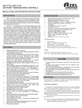
Differential (PWM)
The Differential setting determines the temperature range in which PWM action occurs. This setting should be adjusted to allow PWM
action to occur the majority of the time. Cycle and Differential settings both affect relay “on” and “off” time.
Cycle (PWM)
Cycle provides the greatest control of how often the relay is turning on and off when the measured temperature is in the differential
range. Increasing Cycle will cause the relay to stay on and off longer ( when temperature remains at setpoint). When controlling loads
that respond slowly to the heating/cooling input, the Cycle should be long. When loads respond quickly to heating/cooling input, a
short Cycle is used.
If troubleshooting becomes necessary with the One Stage Setpoint Control 150, follow the testing procedure in step four of the
installation procedure on page 2 of this brochure.
If the display window shows “Err”, the sensor is either open or short circuited, or the sensor temperature is outside the temperature
range of the control. If this type of fault occurs, the control will turn off its relay.
If you do not think the control is operating properly, check to see that the settings have been made correctly and that the problem is
not a result of external causes. Make sure that all wiring connections are solid and the sensor is located in the correct location.
In North America: tekmar Control Systems Ltd., Canada
tekmar Control Systems, Inc., U.S.A.
Head office: 5100 Silver Star Road
Vernon, B.C. Canada V1B 3K4
Tel. (250) 545-7749 Fax. (250) 545-0650
All specifications are subject to change without notice.
Printed in Canada. D 150 - 12/08.
Product designs and literature are Copyright © 2008 by:
tekmar Control Systems Ltd. and tekmar Control Systems, Inc.
4
Limited Warranty and Product Return Procedure
Before you leave
• Install the wiring cover over the wiring chamber and secure it with the screw provided. • Place the front cover on the control to
cover the setting dials and snap it into place. • Place this brochure, and all other brochures relating to the installation, in the protective
plastic bag supplied with the control. • Place the bag in a conspicuous location near the control for future reference. • It is important
to explain the operation of this control within the system to the end user, and anyone else who may be operating the system.
Testing and Troubleshooting
PWM
Dip Switch Down
PWM
Dip Switch Up
PWM
Dip Switch Down
PWM
Dip Switch Up
Limited Warranty The liability of tekmar under this warranty is limited. The Purchaser, by
taking receipt of any tekmar product (“Product”), acknowledges the terms of the Limited
Warranty in effect at the time of such Product sale and acknowledges that it has read and
understands same.
The tekmar Limited Warranty to the Purchaser on the Products sold hereunder is a
manufacturer’s pass-through warranty which the Purchaser is authorized to pass through to
its customers. Under the Limited Warranty, each tekmar Product is warranted against
defects in workmanship and materials if the Product is installed and used in compliance with
tekmar’s instructions, ordinary wear and tear excepted. The pass-through warranty period is
for a period of twenty-four (24) months from the production date if the Product is not installed
during that period, or twelve (12) months from the documented date of installation if installed
within twenty-four (24) months from the production date.
The liability of tekmar under the Limited Warranty shall be limited to, at tekmar’s sole
discretion: the cost of parts and labor provided by tekmar to repair defects in materials and
/ or workmanship of the defective product; or to the exchange of the defective product for a
warranty replacement product; or to the granting of credit limited to the original cost of the
defective product, and such repair, exchange or credit shall be the sole remedy available
from tekmar, and, without limiting the foregoing in any way, tekmar is not responsible, in
contract, tort or strict product liability, for any other losses, costs, expenses, inconveniences,
or damages, whether direct, indirect, special, secondary, incidental or consequential, arising
from ownership or use of the product, or from defects in workmanship or materials, including
any liability for fundamental breach of contract.
The pass-through Limited Warranty applies only to those defective Products returned to
tekmar during the warranty period. This Limited Warranty does not cover the cost of the
parts or labor to remove or transport the defective Product, or to reinstall the repaired or
replacement Product, all such costs and expenses being subject to Purchaser’s agreement
and warranty with its customers.
Any representations or warranties about the Products made by Purchaser to its customers
which are different from or in excess of the tekmar Limited Warranty are the Purchaser’s sole
responsibility and obligation. Purchaser shall indemnify and hold tekmar harmless from and
against any and all claims, liabilities and damages of any kind or nature which arise out of
or are related to any such representations or warranties by Purchaser to its customers.
The pass-through Limited Warranty does not apply if the returned Product has been
damaged by negligence by persons other than tekmar, accident, fire, Act of God, abuse or
misuse; or has been damaged by modifications, alterations or attachments made
subsequent to purchase which have not been authorized by tekmar; or if the Product was
not installed in compliance with tekmar’s instructions and / or the local codes and
ordinances; or if due to defective installation of the Product; or if the Product was not used
in compliance with tekmar’s instructions.
THIS WARRANTY IS IN LIEU OF ALL OTHER WARRANTIES, EXPRESS OR IMPLIED,
WHICH THE GOVERNING LAW ALLOWS PARTIES TO CONTRACTUALLY EXCLUDE,
INCLUDING, WITHOUT LIMITATION, IMPLIED WARRANTIES OF MERCHANTABILITY
AND FITNESS FOR A PARTICULAR PURPOSE, DURABILITY OR DESCRIPTION OF
THE PRODUCT, ITS NON-INFRINGEMENT OF ANY RELEVANT PATENTS OR TRADE-
MARKS, AND ITS COMPLIANCE WITH OR NON-VIOLATION OF ANY APPLICABLE
ENVIRONMENTAL, HEALTH OR SAFETY LEGISLATION; THE TERM OF ANY OTHER
WARRANTY NOT HEREBY CONTRACTUALLY EXCLUDED IS LIMITED SUCH THAT IT
SHALL NOT EXTEND BEYOND TWENTY-FOUR (24) MONTHS FROM THE PRODUC-
TION DATE, TO THE EXTENT THAT SUCH LIMITATION IS ALLOWED BY THE GOVERN-
ING LAW.
Product Warranty Return Procedure All Products that are believed to have defects in
workmanship or materials must be returned, together with a written description of the defect,
to the tekmar Representative assigned to the territory in which such Product is located. If
tekmar receives an inquiry from someone other than a tekmar Representative, including an
inquiry from Purchaser (if not a tekmar Representative) or Purchaser’s customers,
regarding a potential warranty claim, tekmar’s sole obligation shall be to provide the address
and other contact information regarding the appropriate Representative.
  • Page 1 1
  • Page 2 2
  • Page 3 3
  • Page 4 4

tekmar One Stage Setpoint Control 150 Installation guide

Type
Installation guide
This manual is also suitable for

Ask a question and I''ll find the answer in the document

Finding information in a document is now easier with AI