
Use this manual for circuit board 4404-010 Revision A or higher.
Installation/Owner’s Manual
9245
9245
9245
Copyright 2009 DoorKing, Inc. All rights reserved.
Copyright 2017 DoorKing, Inc. All rights reserved.
Heavy-Duty Vehicular Slide Gate Operator
UL 325 Compliant
Date Installed:
Installer/Company Name:
Phone Number:
Leave Manual with Owner
Circuit Board
Serial Number
and Revision Letter:
EXTERNAL ENTRAPMENT PROTECTION MUST be
installed or the gate operator WILL NOT function.
THIS PRODUCT IS TO BE INSTALLED AND SERVICED BY A TRAINED GATE SYSTEMS TECHNICIAN ONLY.
Visit
www.dkslocator.com
to find a professional installing and servicing dealer in your area.
This vehicular gate operator is
designed for
Class III
and
Class IV
applications
ONLY
and must
NEVER
be used in applications
serving the general public.
W
ARNING
M
OV
IN
G
GA
T
E
C
A
N
C
A
U
SE
O
p
e
r
a
t
e
g
a
t
e
o
n
l
y
w
h
e
n
g
a
t
e
a
r
ea
i
s
i
n
s
ig
h
t
an
d
fr
e
e
o
f
p
e
o
p
l
e
a
n
d
o
b
s
t
r
u
c
t
i
o
n
s
.
D
o
n
o
t
a
l
l
o
w
c
h
i
l
d
r
e
n
t
o
p
l
a
y
i
n
g
a
t
e
a
r
e
a
o
r
o
p
e
ra
t
e
g
a
te
.
Do
n
o
t
s
t
a
n
d
i
n
g
a
te
p
a
t
h
o
r
w
a
l
k
t
h
r
o
u
g
h
p
a
t
h
w
h
i
l
e
g
at
e
i
s
m
o
v
i
n
g
.
R
ea
d
o
w
n
e
r
’
s
m
anu
a
l
a
n
d
s
a
fe
ty
i
n
s
t
r
u
c
ti
o
n
s
.
S
E
R
IOUS
IN
J
URY
OR
D
E
A
TH
C
LA
SS
CERTIF
IE
D
TO
CA
N
/C
S
A
C
2
2
.2
N
O
.
24
7
C
ON
F
O
R
MS
T
O
AN
SI
/UL
-3
2
5
V
EHIC
ULAR
GAT
E OP
E
R
AT
O
R
H
P
5
3
3
8
2
MO
DE
L
S
ERI
AL
V
OL
T
S
PHA
S
E
A
M
PS
60
Hz
M
A
X
G
A
TE
L
O
A
D
D
oo
r
K
ing,
In
c
.
,
Inglew
o
od,
C
A
WAR
N
IN
G
M
OVING
G
AT
E
CAN CAU
S
E
O
p
e
ra
t
e
g
a
t
e
o
n
l
y
w
h
e
n
g
a
t
e
a
r
e
a
i
s
in
s
i
g
h
t
a
n
d
f
re
e
o
f
p
e
o
p
l
e
a
n
d
o
b
s
t
ru
c
t
i
o
n
s
.
D
o
n
o
t
a
l
lo
w
c
h
il
d
r
e
n
to
p
la
y
in
g
a
t
e
a
r
e
a
o
r
o
p
e
r
a
t
e
g
a
t
e
.
D
o
n
o
t
s
t
a
n
d
i
n
g
a
t
e
p
a
t
h
o
r
wa
l
k
t
h
ro
u
g
h
p
a
t
h
w
h
i
le
g
a
t
e
i
s
m
o
v
in
g
.
R
e
a
d
o
wn
e
r’
s
m
a
n
u
a
l
a
n
d
s
a
f
e
t
y
i
n
s
t
ru
c
t
io
n
s
.
S
ER
I
O
U
S
I
N
JU
R
Y
O
R
D
EATH
C
LAS
S
CE
R
TI
F
IE
D
TO
CA
N
/
C
S
A
C
2
2
.
2
N
O.
24
7
CO
N
F
OR
M
S
T
O
A
N
S
I
/
U
L
-
32
5
VE
HI
C
U
LA
R GAT
E
OP
E
RA
T
OR
HP
5
3
3
82
M
ODE
L
S
E
R
IAL
V
O
L
T
S
P
H
A
S
E
AM
PS
6
0
Hz
M
AX
G
A
TE
L
O
A
D
D
o
o
r
K
i
n
g
,
I
nc
.
,
I
n
g
le
w
o
o
d
,
C
A
9245-065-G-11-17

9245-065-G-11-17
2
QUICK GUIDE: DIP-Switches
See page 19 for more information about DIP-switches.
1
ON
2 3 4 5 6 7 8 1
ON
2 3 4
The two DIP-switches located on the circuit board are used to program the operator to operate in various modes and to turn on
or off various operating features. Whenever a switch setting is changed, power to the operator must be turned OFF and then
turned back on for the new setting to take affect. Check and review ALL switch settings prior to applying power to the operator.
Switch Function Setting Description
SW 2 - Left 4 Switches
2
Spare
4
Exit Loop Port
Output
Typical
Settings
Full Open Input
Warn Before
Operate
1
The output wired to terminal #4 becomes the output from the loop detector
installed in the EXIT loop port. Plug-in loop detector required for “OFF” function.
Normal Setting. Terminal #4 is a normal full open input for a single gate operator.
Reverses Gate
Stops Gate
Switch Function Setting Description
SW 1 - Right 8 Switches
OFF
ON
4-OFF
4-OFF
4-ON
4-ON
5-OFF
5-ON
5-OFF
5-ON
Auto-Close
Timer
Relay Activation
and
LED Indicator
Light Activation
2
1
3
4 and 5
7
8
OFF
ON
OFF
ON
Normal Setting. No sound.
Internal alarm will sound before gate starts and throughout gate’s cycle.
Auto-close timer is OFF. Manual input required to close gate.
Auto-close timer is ON. Adjustable from 1-23 seconds to close gate.
Self-Test
Gate Opens
Uphill
3
Gate Opens
Downhill
6
Relay activates and LED is ON when the gate is fully open.
Relay activates and LED is ON when the gate is not closed.
Relay activates and LED is ON when the gate is opening and open.
Relay activates and LED is ON when the gate is opening and closing.
Changes the direction
the operator will
open/close the gate.
Opening direction
using ON setting.
Opening direction
using OFF setting.
OFF
ON
Normal Setting. Timer will function normally.
Opening gate will stop and begin to close as soon as all reversing inputs (Reverse
loops, photo sensors) are cleared regardless of the distance the gate has opened.
OFF
ON
Normal Setting. Normal gate operation.
Self-test mode. Operator MUST be disconnected from gate to run self-test.
OFF
ON
Normal Setting. Normal gate operation.
MUST be ON if gate opens UPHILL.
OFF
ON
Normal Setting. Normal gate operation.
MUST be ON if gate opens DOWNHILL.
OFF
Leave in the OFF position.
Left 4 Switches - SW 2
SW 2 is Upside-Down on Circuit Board.
SW 1 - Right 8 Switches
SW 1 is Upside-Down on Circuit Board.
OFF
ON
Normal Setting. Input to terminal #6 and/or reverse loops will REVERSE gate
during CLOSE cycle.
Input to terminal #6 and/or reverse loops will STOP gate during CLOSE cycle.
Quick-Close
Timer Override
Jumper
Wire
Needed
Chain Configuration
1
ON
2 3 4 5 6 7 8 1
ON
2 3 4
The two DIP-switches located on the circuit board are used to program the operator to operate in various modes and to turn on
or off various operating features. Whenever a switch setting is changed, power to the operator must be turned OFF and then
turned back on for the new setting to take affect. Check and review ALL switch settings prior to applying power to the operator.
Switch Function Setting Description
SW 2 - Left 4 Switches
2
Spare
4
Exit Loop Port
Output
Typical
Settings
Full Open Input
Warn Before
Operate
1
The output wired to terminal #4 becomes the output from the loop detector
installed in the EXIT loop port. Plug-in loop detector required for “OFF” function.
Normal Setting. Terminal #4 is a normal full open input for a single gate operator.
Reverses Gate
Stops Gate
Switch Function Setting Description
SW 1 - Right 8 Switches
OFF
ON
4-OFF
4-OFF
4-ON
4-ON
5-OFF
5-ON
5-OFF
5-ON
Auto-Close
Timer
Relay Activation
and
LED Indicator
Light Activation
2
1
3
4 and 5
7
8
OFF
ON
OFF
ON
Normal Setting. No sound.
Internal alarm will sound before gate starts and throughout gate’s cycle.
Auto-close timer is OFF. Manual input required to close gate.
Auto-close timer is ON. Adjustable from 1-23 seconds to close gate.
Self-Test
Gate Opens
Uphill
3
Gate Opens
Downhill
6
Relay activates and LED is ON when the gate is fully open.
Relay activates and LED is ON when the gate is not closed.
Relay activates and LED is ON when the gate is opening and open.
Relay activates and LED is ON when the gate is opening and closing.
Changes the direction
the operator will
open/close the gate.
Opening direction
using ON setting.
Opening direction
using OFF setting.
OFF
ON
Normal Setting. Timer will function normally.
Opening gate will stop and begin to close as soon as all reversing inputs (Reverse
loops, photo sensors) are cleared regardless of the distance the gate has opened.
OFF
ON
Normal Setting. Normal gate operation.
Self-test mode. Operator MUST be disconnected from gate to run self-test.
OFF
ON
Normal Setting. Normal gate operation.
MUST be ON if gate opens UPHILL.
OFF
ON
Normal Setting. Normal gate operation.
MUST be ON if gate opens DOWNHILL.
OFF
Leave in the OFF position.
Left 4 Switches - SW 2
SW 2 is Upside-Down on Circuit Board.
SW 1 - Right 8 Switches
SW 1 is Upside-Down on Circuit Board.
OFF
ON
Normal Setting. Input to terminal #6 and/or reverse loops will REVERSE gate
during CLOSE cycle.
Input to terminal #6 and/or reverse loops will STOP gate during CLOSE cycle.
Quick-Close
Timer Override
Jumper
Wire
Needed
Chain Configuration
Quick Guide - 1

9245-065-G-11-17
3
Quick Guide - 2
NC
NO
P7
20 19
19
18
18
17 16 15 14 13 12 11 10 9 8 7 6 5 4 3 2 1
Current Sensor
Current Sensor
Earth Ground
Motor Hot
Motor Neutral
Dry Relay Contact
Gate Tracker - Data
Gate Tracker - Busy
Entrapment Alarm
Alarm Reset
Full Open
Dry Relay Contact
24 VAC - 250 mA max.
Full Open
Partial Open
Standard Reverse OR Stop
Low Voltage Common
Low Voltage Common
Low Voltage Common
Low Voltage Common
3-Button Full Open
(DoorKing 3-Button Station ONLY)
3-Button Close
(DoorKing 3-Button Station ONLY)
4404
Operation of relay is dependent on
setting of SW 1, switches 4 and 5.
See page 18 and 19 for DIP-switch
function descriptions.
Relay contacts can be set for
Normally Open (NO) or Normally
Closed (NC) operation.
Contact rating is 1 amp maximum
at 24-volts DC.
NC
NO
Used in conjunction with the
circuit board inherent
reversing sensors. See page
21 for further information.
DANGER
HIGH VOLTAGE!
1
ON
2 3 4 5 6 7 8
SW 1 is Upside-Down on Board
1
ON
2 3 4 5 6 7 8
SW 1 is Upside-Down on Board
1
ON
2 3 4 5 6 7 8
SW 1 is Upside-Down on Board
This input ONLY fuctions when gate is fully opened or in the
closing cycle.
• When gate is closing: SW 1, switch 7 is OFF, an input to
terminal #6 (eg: photo beam gets obstructed) will reverse and
open the gate.
Note: If the auto-close timer is ON, when
gate reaches the open position, timer will
not close the gate. Another input command
is needed to reset and close the gate.
• When gate is closing: SW 1, switch 7 is ON, an input to
terminal #6 (eg: photo beam gets obstructed) will stop the
gate, then continue to close the gate when input is clear
(Used to help prevent tailgating vehicles from unauthorized
enrty). See page 19 for more information.
For long gate applications. An input device connected to
terminal #5 will open the gate to the partial open setting,
See page 20 for more information.
Auxiliary Common
Terminal
Connect any low
voltage common wire
to these 2 terminals.
#1 - Jumper Wire - SW 1, switch 3 OFF (Single Operator Exit Loop Partial Open)
#2 - Jumper Wire - SW 1, switch 3 OFF (Dual Operators Full Open)
16
17
11
12
6
4
5
Main Terminal Input LEDs Note: The LED
that is above the main terminal wiring input
will light when that terminal input gets
activated.
#4
#2
#5#6#7#8#9#10
Main Terminal Input LEDs
#1 Terminal #4 jumpered to terminal #5 will PARTIALLY open an
automatic exit loop using a single channel plug-in loop detector
installed in the exit loop port when using a single gate operator.
#2 Terminal #4 jumpered to terminal #2 will FULLY open
bi-parting gates using a dual channel plug-in loop detector
installed in the exit loop port when using dual gate operators.
• SW 1, switch 3 is ON, terminal #4 functions as a normal FULL
open input. (Normal Setting). Single operator use ONLY.
• SW 1, switch 3 is OFF, input to terminal #4
becomes the output from a plug-in loop
detector installed in the EXIT loop port of the
circuit board. A jumper wire is needed to open
and close the gate(s) for these applications:
QUICK GUIDE: Terminal Descriptions
See page 28 for terminal wiring.
(See note)
Main Terminal #3 Note:
Exceeding 250 mA of power from this terminal
may cause the circuit board transformer to
overheat, causing intermittent problems.

9245-065-G-11-17
4
Class of Operation Series 9245 - UL 325 Class III, IV
Type of Gate Vehicular Slide Gates Only
Operating Temperature 10° F to 140° F (-12° C to 62° C)
“Optional” heater kits recommended for colder temperatures.
Inherent Entrapment Protection Device Inherent Reverse Sensor System (Type A)
External Entrapment Protection Device Inputs Connection inputs for Non-contact Sensor - Photo Sensor (Type B1)
(Monitored Inputs) Connection input for Contact Sensor - Reversing Edge (Type B2)
Power Failure Operation Fail-Safe
SPECIFICATIONS
WARNING
MOVING GATE CAN CAUSE
Operate gate only when gate area is in sight
and free of people and obstructions.
Do not allow children to play in gate area
or operate gate.
Do not stand in gate path or walk through
path while gate is moving.
Read owner’s manual and safety instructions.
SERIOUS INJURY OR DEATH
CLASS
CERTIFIED TO
CAN/CSA C22.2 NO. 247
CONFORMS TO
ANSI/UL-325
VEHICULAR GATE OPERATOR
HP
53382
MODEL
SERIAL
VOLTS PHASE
AMPS 60 Hz
MAX GATE LOAD
DoorKing, Inc., Inglewood, CA
Heavy-Duty Pedestal
Mounting Stand Kit
Included with Standard Model Only
Specialized Base Plate Model
Thicker base plate without mounting holes.
Standard Model
16.5”
18”
12”
31.5”
20”
Volt/Phase
208 / 1
230 / 1
Horse
Power
3
Gearbox
10:1
Mech. Disc
Brake
Yes
Slow
Down
Yes
Electronic
Brake
Yes
AC
Module
10 HP
Amps
12.8
12.6
Chain #
80
Max Gate
Weight - lbs.
8000
Max Gate
Length - ft.
100
Installed
Level
Gate
Cycles
Continuous
2 ft/sec
Adjustable
Gate
Speed
With
Standard
Model
Only
Pedestal
Stand Kit
On
Specialized
Model
Only
Special
Base Plate
DoorKing, Inc. reserves the right to make changes in the products described in this manual without notice and without obligation of DoorKing, Inc. to notify any persons
of any such revisions or changes. Additionally, DoorKing, Inc. makes no representations or warranties with respect to this manual. This manual is copyrighted, all rights
reserved. No portion of this manual may be copied, reproduced, translated, or reduced to any electronic medium without prior written consent from DoorKing, Inc.
16”
35.5”
20”
18”
16”
4”
WA
RNING
M
O
V
IN
G
G
A
T
E
C
A
N
C
A
US
E
Op
e
r
a
t
e
gat
e
o
n
l
y
w
he
n
g
a
t
e
ar
e
a
i
s
i
n
si
gh
t
a
n
d
f
r
e
e
o
f
p
e
o
p
l
e
a
n
d
o
b
s
t
r
u
c
t
i
o
n
s
.
D
o
n
o
t
a
l
l
o
w
c
h
i
l
d
r
e
n
t
o
p
l
a
y
i
n
g
at
e
a
r
ea
o
r
o
p
e
ra
t
e
g
a
t
e
.
Do
n
o
t
s
t
a
n
d
i
n
g
a
t
e
p
a
t
h
o
r
w
a
l
k
t
h
r
o
u
g
h
p
a
t
h
w
h
i
l
e
g
a
t
e
i
s
mo
v
i
n
g
.
Re
a
d
o
w
n
e
r’
s
m
a
n
u
a
l
a
n
d
sa
f
e
t
y
i
n
s
t
r
u
c
t
i
o
n
s
.
SE
R
IO
U
S IN
JU
R
Y
O
R
D
E
ATH
C
L
A
SS
C
E
R
T
IF
IE
D
T
O
C
AN/CS
A
C
2
2
.2
NO.
2
4
7
CONF
O
RMS
T
O
A
NS
I
/UL
-3
2
5
V
E
H
IC
U
L
A
R
G
A
T
E
O
P
E
R
AT
O
R
HP
5
3
3
8
2
M
ODE
L
S
E
RI
A
L
V
OL
T
S
P
HA
SE
A
M
P
S6
0
Hz
M
A
X
GA
T
E
L
OA
D
Do
o
rK
i
ng
,
I
nc.,
I
ng
l
e
w
ood
,
C
A
Specialized
base plate
model
operator’s
housing
dimensions
are the
same as
the
standard
model.
Thinner base plate with mounting
holes for the pedestal mounting stand.
This vehicular gate operator is designed for Class III
and Class IV applications only and must never be
used in applications serving the general public.
TWO (2) Entrapment Protection
Devices are REQUIRED for
UL 325 compliance.
Type B1 and B2 MUST be
MONITORED when used.

9245-065-G-11-17
1
TABLE OF CONTENTS
QUICK GUIDES
Quick Guide: DIP-Switches
Quick Guide: Terminal Descriptions
Operator Specifications
Slide Gate Requirements
Safety Information for Slide Gate Operators
Gate Construction
Important Safety Instructions
Instructions regarding intended installation:
Important Notices
UL325 Entrapment Protection
Glossary
Quick Guide-1
Quick Guide-2
Previous Page
2
3
4
4
4
5
6
7
SECTION 1 - INSTALLATION 8
8
8
9-10
11
12
13
14
15
1.1 Gate Hardware
1.2 Underground Conduit Requirements
1.3 Installation Options, Gate Types
1.4 Pedestal Mounting Stand Installation
1.5 “Specialized Base Plate” Installation
1.6 Chain Tray Kit Installation
1.7 Chain Installation
1.8 Installation of Warning Signs
SECTION 2 - AC POWER TO OPERATOR(S) 15
15
16
2.1 High Voltage Wire Runs
2.2 High Voltage Power Connection and Battery Power
SECTION 7 - MAINTENANCE AND TROUBLESHOOTING 33
7.1 Maintenance
7.2 Built-In Diagnostic Tests
7.3 Troubleshooting
7.4 Accessory Items
9245 Wiring Schematics
33
34
34-35
36
37
SECTION 6 - OPERATING INSTRUCTIONS 30
6.1 AC Power and Reset Button
6.2 Shutdown Conditions
6.3 Manual Gate Operation
30
31
32
SECTION 4 - ENTRAPMENT AND SAFETY PROTECTION 23
4.1 UL 325 Terminal Description
4.2 Entrapment Protection Device Locations
4.3 Loop Detector Wiring
23
24-25
26
SECTION 5 - MAIN TERMINAL WIRING 27
5.1 Main Terminal Description
5.2 Control Wiring for Single/Primary Operator
5.3 Auxiliary Device Wiring
27
28
29
SECTION 3 - ADJUSTMENTS 17
3.1 4404 Circuit Board Description and Adjustments
3.2 DIP-Switch SW 1 and SW 2 Settings
3.3 Limit Switches
3.4 Inherent Reverse Sensor Adjustment
3.5 Current Sensor Adjustment
3.6 AC Module Adjustment
17
18-19
20
21
21
22

9245-065-G-11-17
2
Slide Gate Requirements
The operator is intended for installation only on gates used for vehicles. Pedestrians must be supplied with a separate
access opening. The pedestrian access opening shall be designed to promote pedestrian usage. Locate the gate such that
persons will not come in contact with the vehicular gate during the entire path of travel of the vehicular gate.
(ref. UL 325 56.8.4.b)
All openings of a horizontal slide gate are guarded or
screened from the bottom of the gate to a minimum
of six (6) feet (1.83 m) above the ground to prevent
a 2 1/4 inch (57.2 mm) diameter sphere from
passing through the openings anywhere in the gate
and in that portion of the adjacent fence that the
gate covers in the open position.
(ref. ASTM F2200-11a, 6.1.2)
A gap, measured in the horizontal plane parallel to
the roadway, between a fixed stationary object
nearest the roadway (such as a gate support
post) and the gate frame when the gate is in
either the fully open position or the fully closed
position, shall not exceed 2 1/4 inch (57.2 mm).
(ref. ASTM F2200 6.1.4)
2 1/4” maximum gap area
High Risk of Entrapment Area
High Risk of Entrapment Area
X X X X X X X X X X X X X X X X X X X X X X X X X X X X X X X X X X X X X X X X X X X X X X X X X X X X X X X X X X X X X X X X X X X X X
X X X X X X X X X X X X X X X X X X X X X X X X X X X X X X X X X X X X X X X X X X X X X X X X X X X X X X X X X X X X X
X X X
Adjacent fence that covers open gate position.
Gate Support Post
Fence
Closed Gate
Gate Frame
Note: A filler post or
barrier may need to
be installed in the gap
area to reduce the
distance to 2 1/4
inches or less. A
contact sensor should
be installed in this
area for safety.
(See on next
page and page 24).
A
Gates shall be designed, constructed and
installed to not fall over more than 45
degrees from the vertical plane, when a gate
is detatched from the supporting hardware.
Guide
Rollers
Fall Over Bracket
Illustrations not to scale.
Screened Wire Mesh Less than 2 1/4”
DoorKing recommends installing screened wire
mesh on the ENTIRE gate AND and on that portion
of the adjacent fence that the gate covers in the
o
p
en
p
osition.
(
See above
)
.

9245-065-G-11-17
3
Reverse
Loop
Automatic
Exit Loop
Minimizes the potential
of the gate closing
when a vehicle is
present. Number and
placement of loops is
dependent on the
application.
Reverse
Loop
Minimizes the potential
of the gate closing
when a vehicle is
present. Number and
placement of loops is
dependent on the
application.
(Optional) will
provide an open
command to the
gate operator(s)
when a vehicle is
exiting the property.
Warning Sign
Moving Gate Can Cause
Serious Injury or Death
KEEP CLEAR! Gate may move at any time
without prior warning.
Do not let children operate the gate or play
in the gate area.
This entrance is for vehicles only.
Pedestrians must use separate entrance.
Moving Gate Can Cause
Serious Injury or Death
KEEP CLEAR! Gate may move at any time
without prior warning.
Do not let children operate the gate or play
in the gate area.
This entrance is for vehicles only.
Pedestrians must use separate entrance.
11
A
B
C
Closed Gate
Secure Side of Gate
Non-Secure Side of Gate
2
Safety Information for Slide Gate Operators
Physical Stop
Positive stops shall be required
to limit travel to the designed
fully open and fully closed
positions. These stops shall be
installed either at the top of the
gate, or at the bottom of the
gate where such stops shall
horizontally or vertically project
no more than is required to
perform their intended function.
Physical Stops
Permanently mounted and easily
visible from either side of the gate.
Warning Signs
Non-Contact Sensors (Photo Sensors)
1
2
Minimizes the potential of the gate closing on vehicular or
other traffic that loops cannot sense. It can be installed on the
secure OR non-secure side of gate.
Helps minimize the potential of entrapment during the back
travel of the gate.
Entrapment protection devices are required to reduce the risk of injury.
Install sensors where the risk of entrapment or obstruction exists while
gate is moving. Individual requirements will vary. See pages 23-26 for
more information on typical layout locations and setup.
Contact Sensor (Reversing Edges)
A
Minimizes the potential of the gate closing on vehicular
or other traffic that loops cannot sense.
Installed on the fence to help minimize the potential of
entrapment between the gate and fence. A filler post or
barrier MAY need to be installed between fence and gate.
B
C
Helps minimize the potential of entrapment during the
back travel of the gate.
Guide Rollers
See previous page for more information.
Separate
Pedestrian
Walkway
Located so pedestrians
cannot come in contact
with the vehicular gate.
High Risk of Entrapment Area
X X X X X X X
X X X X X X X X X
Screened
Wire Mesh
May be necessary on part
of fence AND entire gate.
See previous page for more
information.
FenceFence
Illustration not to scale.
Note: DO NOT USE MMTC,
Inc. Model IR55 Photo
Sensor - P/N 8080-010 for
the 9200 series slide gate
operator.
External entrapment
protection devices are
REQUIRED for operator
to function.

9245-065-G-11-17
4
Instructions regarding intended installation:
Vehicular gates should be constructed and installed in accordance with ASTM F2200; Standard Specification for Automated Vehicular Gate Construction.
For a copy of this standard, contact ASTM directly at 610-832-9585; [email protected]; or www.astm.org.
Important Safety Instructions
WARNING - To reduce the risk of injury or death:
1. READ AND FOLLOW ALL INSTRUCTIONS.
2. Never let children operate or play with gate controls. Keep the remote control away from children.
3. Always keep people and objects away from gate. NO ONE SHOULD CROSS THE PATH OF THE MOVING GATE.
4. Test the operator monthly. The gate MUST reverse on contact with a rigid object or stop or reverse when an object activates the non-contact sensors.
After adjusting the force or the limit of travel, retest the gate operator. Failure to adjust and retest the gate operator properly can increase the risk of
injury or death.
5. Use the emergency release only when the gate is not moving.
6. KEEP GATES PROPERLY MAINTAINED. Read the owner's manual. Have a qualified service person make repairs to gate hardware.
7. The entrance is for vehicles only. Pedestrians must use separate entrance.
8. SAVE THESE INSTRUCTIONS!
• Install the gate operator only if:
1. The operator is appropriate for the construction of the gate and the usage class of the gate.
2. All openings of a horizontal slide gate are guarded or screened from the bottom of the gate to a minimum of 6 feet (1.83 m) above the ground to
prevent a 2 ¼ inch (57.2 mm) diameter sphere from passing through the openings anywhere in the gate, and in that portion of the adjacent fence
that the gate covers in the open position.
3. All exposed pinch points are eliminated or guarded.
4. Guarding is supplied for exposed rollers.
• The operator is intended for installation only on gates used for vehicles. Pedestrians must be supplied with a separate access opening. The pedestrian
access opening shall be designed to promote pedestrian usage. Locate the gate such that persons will not come in contact with the vehicular gate
during the entire path of travel of the vehicular gate.
• The gate must be installed in a location so that enough clearance is supplied between the gate and adjacent structures when opening and closing to
reduce the risk of entrapment. Swinging gates should not open into public access areas.
• The gate must be properly installed and work freely in both directions prior to the installation of the gate operator. Do not over-tighten the operator
clutch, pressure relief valve or reduce reversing sensitivity to compensate for a damaged gate.
• For gate operators utilizing Type D protection:
1. The gate operator controls must be placed so that the user has full view of the gate area when the gate is moving.
2. A warning placard shall be placed adjacent to the controls.
3. An automatic closing device (such as a timer, loop sensor, or similar device) shall not be employed.
4. No other activation device shall be connected.
• Controls intended for user activation must be located at least six feet (6’) away from any moving part of the gate and where the user is prevented from
reaching over, under, around or through the gate to operate the controls. Outdoor or easily accessible controls should have a security feature to prevent
unauthorized use.
• The Stop and/or Reset button must be located in the line-of-sight of the gate. Activation of the reset control shall not cause the operator to start.
• A minimum of two (2) WARNING SIGNS shall be installed, one on each side of the gate where easily visible.
• For gate operators utilizing a non-contact sensor:
1. See the instructions on the placement of non-contact sensors for each type of application.
2. Care shall be exercised to reduce the risk of nuisance tripping, such as when a vehicle trips the sensor while the gate is still moving in the opening direction.
3. One or more non-contact sensors shall be located where the risk of entrapment or obstruction exist, such as the perimeter reachable by a moving
gate or barrier.
• For gate operators utilizing contact sensors:
1. One or more contact sensors shall be located where the risk of entrapment or obstruction exist, such as at the leading edge, trailing edge, and
post mounted both inside and outside of a vehicular horizontal slide gate.
2. One or more contact sensors shall be located at the bottom edge of a vehicular vertical lift gate.
3. One or more contact sensors shall be located at the pinch point of a vehicular vertical pivot gate.
4. A hardwired contact sensor shall be located and its wiring arranged so that the communication between the sensor and the gate operator is not
subjected to mechanical damage.
5. A wireless contact sensor such as one that transmits radio frequency (RF) signals to the gate operator for entrapment protection functions shall
be located where the transmission of the signals are not obstructed or impeded by building structures, natural landscaping or similar
obstructions. A wireless contact sensor shall function under the intended end-use conditions.
6. One or more contact sensors shall be located at the bottom edge of a vertical barrier (arm).
ASTM F2200 Standard for Gate Construction

9245-065-G-11-17
5
Vehicular gate operator products provide convenience and security. However, gate operators must use high levels of force to move gates and most people
underestimate the power of these systems and do not realize the potential hazards associated with an incorrectly designed or installed system.
These hazards may include:
• Pinch points
• Entrapment areas
• Reach through hazards
• Absence of entrapment protection devices
• Improperly located access controls
• Absence of vehicle protection devices
• Absence of controlled pedestrian access
In addition to these potential hazards, automated vehicular gate systems must be installed in accordance with the UL 325 Safety Standard and the ASTM
F2200 Construction Standard. Most people are unaware of, or are not familiar with, these standards. If an automated vehicular gate system is not properly
designed, installed, used and maintained, serious injuries or death can result. Be sure that the installer has instructed you on the proper operation of the
gate and gate operator system.
Be sure that the installer has trained you about the basic functions of the required reversing systems associated with your gate operating system and how
to test them. These include reversing loops, inherent reversing system, electric edges, photoelectric cells, or other external devices.
• This Owner’s Manual is your property. Keep it in a safe place for future reference.
• Be sure that all access control devices are installed a minimum distance of 6 feet away from the gate and gate operator, or in such a way that a
person cannot touch the gate or gate operator while using the device. If access control devices are installed in violation of these restrictions,
immediately remove the gate operator from service and contact your installing dealer.
Important Notices
• Loops and loop detectors, photo-cells or other equivalent devices must be installed to prevent the gate from closing on vehicular traffic.
• The speed limit for vehicular traffic through the gate area is 5 MPH. Install speed bumps and signs to keep vehicular traffic from speeding
through the gate area. Failure to adhere to posted speed limits can result in damage to the gate, gate operator, and to the vehicle.
• Be sure that all persons who will use the gate system are familiar with the proper use of the gate and gate operator and are familiar with the
possible hazards associated with the gate system.
• Be sure that warning signs are permanently installed on both sides of the gate in an area where they are fully visible to traffic.
• It is your responsibility to periodically check all entrapment protection devices. If any of these devices are observed to function improperly,
remove the operator from service immediately and contact your installing or servicing dealer.
• Follow the recommended maintenance schedule.
• Do not allow children to play in the area of the operator or to play with any gate-operating device.
• To remove the gate operator from service, operate the gate to the full open position and then shut off power to the operator at the service panel.
Opening device MUST be mounted a
minimum of 6 feet from the gate and
NOT accessible through the gate!

9245-065-G-11-17
6
UL325 Entrapment Protection
Class I - Residential
Vehicular Gate Operator
Entrapment Protection Types
Class II - Commercial/General Access
Vehicular Gate Operator
Class III - Industrial/Limited Access
Vehicular Gate Operator
Class IV -
Restricted Access
Vehicular Gate Operator
A vehicular gate operator (or system) intended for use in garages
or parking areas associated with a residence of one-to four single
families.
A vehicular gate operator (or system) intended for use in a
commercial location or building such as a multi-family housing
unit (five or more single family units), hotel, garages, retail store,
or other buildings accessible by or servicing the general public.
A vehicular gate operator (or system) intended for use in an
industrial location or building such as a factory or loading dock
area or other locations not accessible by or intended to service
the general public.
A vehicular gate operator (or system) intended for use in a
guarded industrial location or building such as an airport security
area or other restricted access locations not servicing the general
public, in which unauthorized access is prevented via supervision
by security personnel.
Gate Operator Category
UL 325 Classifications
Type A - Inherent entrapment protection system.
Type B1 - Non-contact sensor (photoelectric sensor or the equivalent).
Type B2 - Contact sensor (edge device or equivalent).
Type C - Inherent force limiting, inherent adjustable clutch or inherent pressure relief device.
Type D - Actuating device requiring constant pressure to maintain opening or closing motion of the gate.
* B1 and B2 means of entrapment protection must be MONITORED.
Vertical Barrier Note: Barrier gate operators (arm)
that is not intended to move toward a rigid object
closer than 16 inches (406 mm) are not required to
be provided with a means of entrapment protection.
STATE PRISON
Horizontal Slide, Vertical Lift, Vertical Pivot Swing, Vertical Barrier (Arm)
A, B1*, B2* or D A, B1*, B2*, C or D
Effective January 12, 2016
Authorized
Personnel ONLY
ident
e Operator
or system) inte
ercial/General

9245-065-G-11-17
7
Glossary
GATE - A moving barrier such as a swinging, sliding, raising, lowering, or the like, barrier, that is a stand-alone passage
barrier or is that portion of a wall or fence system that controls entrance and/or egress by persons or vehicles and
completes the perimeter of a defined area.
RESIDENTIAL VEHICULAR GATE OPERATOR – CLASS I - A vehicular gate operator (or system) intended for use in a home
of one-to four single family dwelling, or garage or parking area associated therewith.
COMMERCIAL / GENERAL ACCESS VEHICULAR GATE OPERATOR - CLASS II - A vehicular gate operator (or system)
intended for use in a commercial location or building such as a multi-family housing unit (five or more single family units),
hotels, garages, retail store, or other building servicing the general public.
INDUSTRIAL / LIMITED ACCESS VEHICULAR GATE OPERATOR - CLASS III - A vehicular gate operator (or system)
intended for use in an industrial location or building such as a factory or loading dock area or other locations not intended
to service the general public.
RESTRICTED ACCESS VEHICULAR GATE OPERATOR - CLASS IV - A vehicular gate operator (or system) intended for use in
a guarded industrial location or building such as an airport security area or other restricted access locations not servicing
the general public, in which unauthorized access is prevented via supervision by security personnel.
VEHICULAR BARRIER (ARM) OPERATOR (OR SYSTEM) - An operator (or system) that controls a cantilever type device (or
system), consisting of a mechanical arm or barrier that moves in a vertical arc, intended for vehicular traffic flow at
entrances or exits to areas such as parking garages, lots or toll areas.
VEHICULAR HORIZONTAL SLIDE-GATE OPERATOR (OR SYSTEM) - A vehicular gate operator (or system) that controls a
gate which slides in a horizontal direction that is intended for use for vehicular entrance and exit to a drive, parking lot, or
the like.
VEHICULAR SWING-GATE OPERATOR (OR SYSTEM) - A vehicular gate operator (or system) that controls a gate which
moves in an arc in a horizontal plane that is intended for use for vehicular entrance and exit to a drive, parking lot, or the
like.
SYSTEM - In the context of these requirements, a system refers to a group of interacting devices intended to perform a
common function.
WIRED CONTROL - A control implemented in a form of fixed physical interconnections between the control, the associated
devices, and an operator to perform predetermined functions in response to input signals.
WIRELESS CONTROL - A control implemented in means other than fixed physical interconnections (such as radio waves or
infrared beams) between the control, the associated devices, and an operator to perform predetermined functions in
response to input signals.
INHERENT ENTRAPMENT PROTECTION SYSTEM - A system, examples being a motor current or speed sensing system,
which provides protection against entrapment upon sensing an object and is incorporated as a permanent and integral part
of the operator.
EXTERNAL ENTRAPMENT PROTECTION DEVICE - A device, examples being an edge sensor, a photoelectric sensor, or
similar entrapment protection device, which provides protection against entrapment when activated and is not incorporated
as a permanent part of an operator.
ENTRAPMENT - The condition when an object is caught or held in a position that increases the risk of injury.

9245-065-G-11-17
8
1.2 Underground Conduit Requirements
SECTION 1 - INSTALLATION
Prior to beginning the installation of the slide gate operator, we suggest that you become familiar with the
instructions, illustrations, and wiring guide-lines in this manual. This will help insure that your installation is
performed in an efficient and professional manner compliant with UL 325 safety and ASTM F2200 construction
standards.
The proper installation of the vehicular slide gate operator is an extremely important and integral part of the
overall access control system. Check all local building ordinances and building codes prior to installing this
operator. Be sure your installation is in compliance with local codes.
1.1 Gate Hardware
DoorKing has a full line of Tandem V-wheels that are ideal for heavy gates and
will ensure safe, reliable and long lasting gate operation. The gate must be
properly installed and roll smoothly in both directions.
Guide Rollers with Protective Covers
Helps to minimize a pinch point on the
gate.
4 Inch6 Inch
Primary/Secondary Interconnection Cable (Dual Operator Application Only)
Sweeps
Concrete Pad
Concrete Pad
3/4 Inch Minimum
Single/
Primary
Operator
Position
Secondary
Operator
Position
External Safety Devices, Control and/or P.A.M.S. Wires (Low Voltage wire insulation)
Loop Lead-In Wires (Low Voltage wire insulation)
AC Input Power (High Voltage wire insulation)
AC Input Power (High Voltage wire insulation)
Elbow
NO
Sweep
YES
• The conduit requirements are for a typical slide gate operator installation (the secondary operator is shown for those
applications where a secondary operator may be used). The conduit requirements for your application may vary from
this depending on your specific needs.
• Use only sweeps for conduit bends. Do not use 90° elbows as this will make wire pulls very
difficult and can cause damage to wire insulation. DoorKing recommends using 3/4-inch conduit.
• Installation of External Entrapment Protection Devices are REQUIRED (photo sensors and/or reversing edges).
• Be sure that all conduits are installed in accordance with local codes.
• Never run low voltage rated wire insulation in the same conduit as high voltage rated wire insulation.

9245-065-G-11-17
9
1.3 Installation Options
A chain tray is recommended for gates that are longer than 20 feet in length. The chain tray helps support the weight of the
chain and reduce the chain stretching that occurs over time. DoorKing offers a chain tray kit that will fit any length gate
(P/N 2601-270 10 ft. connecting sections). See page 13 for details.
See pages 11, 13 and 14 for details.
See pages 12 and 14 for details.
Concrete Pad
Underground
Concrete
WARNING
M
O
V
I
N
G
G
A
T
E
C
A
N
C
A
USE
O
p
e
ra
t
e
g
a
t
e
o
n
l
y
w
h
e
n
g
a
t
e
a
r
e
a
i
s
i
n
s
ig
h
t
a
n
d
f
r
e
e
o
f
p
e
o
p
l
e
a
n
d
o
b
s
t
r
u
c
t
i
o
n
s
.
Do
n
o
t
a
l
l
o
w
c
h
il
d
r
e
n
t
o
p
l
a
y
i
n
g
at
e
a
r
e
a
o
r
o
p
e
r
ate
g
a
t
e
.
D
o
n
o
t
s
t
a
n
d
in
g
a
t
e
p
at
h
o
r
w
a
lk
t
h
r
o
u
g
h
p
a
t
h
w
h
i
l
e
g
a
t
e
is
mo
v
i
n
g
.
R
e
a
d
o
w
n
e
r
’
s
m
a
n
u
a
l
a
n
d
s
a
f
e
t
y
i
n
s
t
r
u
c
t
io
n
s
.
S
E
RIOUS
IN
JURY OR DE
AT
H
C
L
A
SS
C
E
R
TI
F
I
ED
TO
C
AN
/
C
S
A
C
2
2
.
2 NO.
2
47
C
O
N
F
O
R
M
S
T
O
A
NSI
/
U
L
-
3
2
5
V
E
H
IC
U
L
AR
G
AT
E
O
P
E
R
A
T
O
R
H
P
5
3
3
8
2
M
O
D
E
L
S
ERI
A
L
V
O
L
T
SP
HAS
E
A
M
P
S
6
0
H
z
M
A
X
G
ATE
L
O
AD
D
o
orK
i
n
g
,
I
n
c.,
I
n
g
l
e
woo
d
,
CA
Pedestal
Mounting
Stand
Underground Conduit Runs
Chain Tray
Chain Tray
WA
R
N
I
N
G
M
O
V
I
N
G
G
A
T
E
C
A
N
C
A
U
S
E
O
p
e
r
a
t
e
g
a
t
e
o
n
l
y
w
h
e
n
g
a
t
e
a
r
e
a
i
s
i
n
s
i
g
h
t
a
n
d
f
r
e
e
o
f
p
e
o
p
l
e
a
n
d
o
b
s
t
r
u
c
t
i
o
n
s
.
D
o
n
o
t
a
l
l
o
w
c
h
i
l
d
r
e
n
t
o
p
l
a
y
i
n
g
a
t
e
a
r
e
a
o
r
o
p
e
r
a
t
e
g
a
t
e
.
D
o
n
o
t
s
t
a
n
d
i
n
g
a
t
e
p
a
t
h
o
r
w
a
l
k
t
h
r
o
u
g
h
p
a
t
h
w
h
i
l
e
g
a
t
e
i
s
m
o
v
i
n
g
.
R
e
a
d
o
w
n
e
r
’
s
m
a
n
u
a
l
a
n
d
s
a
f
e
t
y
i
n
s
t
r
u
c
t
i
o
n
s
.
S
E
R
I
O
U
S
I
N
J
U
R
Y
O
R
D
E
AT
H
C
L
A
S
S
C
E
R
T
I
F
I
E
D
T
O
C
A
N
/
C
S
A
C
2
2
.
2
N
O
.
2
4
7
C
O
N
F
O
R
M
S
T
O
A
N
S
I
/
U
L
-
3
2
5
V
E
H
I
C
U
L
A
R
G
A
T
E
O
P
E
R
A
TO
R
H
P
5
3382
M
O
D
E
L
S
E
R
I
A
L
V
O
LT
S
P
H
A
S
E
A
M
P
S
6
0
H
z
M
A
X
G
A
T
E
L
O
A
D
D
o
o
r
K
i
n
g
,
I
n
c
.
,
I
n
g
l
e
w
o
o
d
,
C
A
Specialized Base Plate
Conduit

9245-065-G-11-17
10
1.3 Gate Types
Heavy-Duty Box Frame Roller
Heavy-Duty V-Rail V-Wheel Ornamental
Heavy-Duty Ornamental Cantilever
Heavy-Duty Box Frame Cantilever
• Steel or Aluminum.
• 8,000 lb Max. Weight per Gate.
• Single Operator - 100 Ft Max. Gate Length
Dual Operators - 200 Ft Max. Total Gate Length
• Chain tray recommended for gates over 20 ft. per gate.
W
A
R
N
IN
G
M
O
V
I
N
G
G
A
T
E
CA
N
C
A
U
S
E
O
p
e
r
at
e
g
a
t
e
o
n
l
y
w
h
e
n
g
a
t
e ar
e
a
i
s
i
n
s
i
g
h
t
a
n
d
f
re
e
o
f
p
eo
p
l
e an
d
o
b
s
t
ru
c
t
io
n
s
.
D
o
n
o
t
a
l
l
o
w
c
h
i
l
d
r
e
n
t
o
p
l
a
y
i
n
g
a
t
e
a
re
a
o
r
o
p
er
at
e
g
a
t
e.
D
o
n
o
t
st
a
n
d
i
n
g
a
t
e
p
a
t
h
o
r
w
a
l
k
t
h
r
o
u
g
h
p
a
t
h
w
h
i
l
e
g
a
t
e
is
m
o
v
i
n
g
.
R
ea
d
o
w
n
e
r
’
s
m
a
n
u
a
l
a
n
d
s
a
f
e
t
y
i
n
st
ruc
t
i
o
n
s
.
S
ER
I
O
U
S
I
N
J
U
R
Y
O
R
DEA
TH
C
L
A
S
S
C
E
RT
I
F
I
E
D
T
O
C
A
N
/
C
S
A
C
2
2
.
2
N
O
.
2
4
7
C
O
N
F
O
R
M
S
T
O
A
N
S
I
/
U
L
-
3
2
5
VEH
I
C
U
L
A
R
G
AT
E
O
P
E
R
AT
O
R
HP
5
3
3
8
2
M
O
D
E
L
S
E
R
I
A
L
V
OL
T
S
P
H
A
S
E
A
M
P
S
6
0
H
z
M
A
X
G
A
T
E
L
O
A
D
Do
o
rK
i
n
g
,
I
n
c.,
I
n
g
l
e
w
o
o
d
,
C
A
W
A
R
N
I
N
G
M
O
V
I
N
G
G
A
T
E
C
A
N
C
A
U
S
E
O
p
e
ra
t
e
g
a
t
e
o
n
l
y
w
h
e
n
g
a
t
e
a
r
e
a
i
s
i
n
s
i
g
h
t
a
n
d
f
r
e
e
o
f
p
e
o
p
l
e
a
n
d
o
b
s
t
r
u
c
t
i
o
n
s
.
D
o
n
o
t
a
l
l
o
w
c
h
i
l
d
r
e
n
t
o
p
l
a
y
in
g
a
t
e
a
r
e
a
o
r
o
p
e
r
a
t
e
g
a
t
e
.
D
o
n
o
t
s
t
a
n
d
i
n
g
a
t
e
p
a
t
h
o
r
w
a
l
k
t
h
r
o
u
g
h
p
a
t
h
w
h
i
l
e
g
a
t
e
i
s
m
o
v
in
g
.
R
e
a
d
o
w
n
e
r
’
s
m
a
n
u
a
l
a
n
d
s
a
f
e
t
y
i
n
s
t
r
u
c
t
i
o
n
s
.
S
E
R
I
O
U
S
I
N
J
U
R
Y
O
R
D
E
A
T
H
C
L
A
S
S
C
E
R
T
I
F
I
E
D
T
O
C
A
N
/
C
S
A
C
2
2
.2
N
O
.
2
4
7
C
O
N
F
O
R
M
S
T
O
A
N
S
I
/
U
L
-
3
2
5
V
E
H
I
C
U
L
A
R
G
A
T
E
O
P
E
R
A
T
O
R
H
P
5
3
3
8
2
M
O
D
E
L
S
E
R
I
A
L
V
O
L
T
S
P
H
A
S
E
A
M
P
S
6
0
H
z
M
A
X
G
A
T
E
L
O
A
D
D
o
o
r
K
i
n
g
,
I
n
c
.
,
I
n
g
l
e
w
o
o
d
,
C
A
W
A
R
NIN
G
MO
V
I
N
G
G
A
T
E
C
A
N
C
A
U
S
E
O
p
e
r
a
t
e
g
a
t
e
o
n
l
y
w
h
en
g
a
t
e
ar
e
a
i
s
i
n
si
g
h
t
a
n
d
f
r
e
e
o
f
p
e
o
p
l
e
a
n
d
o
b
st
r
u
c
t
i
o
n
s
.
D
o
n
o
t
al
l
o
w
ch
i
l
d
r
e
n
t
o
p
l
a
y
i
n
g
a
t
e
a
r
ea
o
r
o
p
e
r
at
e
g
a
t
e
.
D
o
n
o
t
s
t
a
n
d
i
n
g
at
e
p
at
h
o
r
w
a
l
k
t
h
r
o
u
g
h
p
at
h
w
h
i
l
e
g
a
t
e
is
m
o
v
in
g
.
R
ead
o
w
n
er
’
s
m
a
n
u
a
l
an
d
sa
f
et
y
i
n
s
t
r
u
ct
i
o
n
s.
S
E
R
I
O
U
S
I
NJU
R
Y
OR
DE
A
TH
C
L
A
S
S
C
E
R
T
I
FI
E
D
T
O
C
A
N
/C
S
A
C
2
2.
2
N
O
.
2
4
7
CO
N
F
O
R
M
S
T
O
A
N
S
I
/U
L
-
3
2
5
V
E
H
I
CU
L
AR
G
A
TE
O
PE
R
A
T
O
R
H
P
5
3
3
8
2
M
O
D
EL
S
E
R
IA
L
V
O
L
TS
P
H
A
S
E
A
M
P
S
6
0
H
z
MA
X
G
A
T
E
L
O
A
D
D
oo
r
K
i
ng
,
I
n
c
.
,
I
ng
le
w
o
o
d
,
C
A
W
A
R
NI
NG
M
O
V
I
N
G
G
A
T
E
CA
N
C
A
U
S
E
O
p
e
r
a
t
e
g
a
t
e
o
n
l
y
wh
e
n
g
a
t
e
a
r
e
a
i
s
i
n
s
i
g
h
t
a
n
d
f
re
e
o
f
p
e
o
p
l
e
a
n
d
o
b
s
t
r
u
c
t
i
o
n
s
.
D
o
n
o
t
a
l
l
o
w
c
h
i
l
d
r
e
n
t
o
p
l
a
y
i
n
g
a
t
e
a
r
e
a
o
r
o
p
e
r
a
t
e
g
a
t
e
.
D
o
n
o
t
s
t
a
n
d
i
n
g
a
t
e
p
a
t
h
o
r
w
a
l
k
t
h
r
o
u
g
h
p
a
t
h
w
h
i
l
e
g
a
t
e
i
s
mo
v
i
n
g
.
R
e
a
d
o
w
n
e
r’
s
m
a
n
u
a
l
a
n
d
s
a
f
e
t
y
i
n
s
t
r
u
c
t
i
o
n
s
.
S
E
R
I
O
U
S
I
N
J
U
R
Y
O
R
D
E
A
T
H
C
L
A
S
S
C
E
R
T
I
F
I
E
D
T
O
C
A
N
/
C
S
A
C
22
.
2
N
O
.
2
4
7
C
O
N
F
O
R
M
S
T
O
A
N
S
I
/
U
L
-
3
2
5
V
E
H
I
C
U
L
A
R
G
A
T
E
O
P
E
R
A
T
O
R
H
P
5
3
3
8
2
M
O
D
E
L
S
E
R
I
A
L
V
O
L
T
S
P
H
A
S
E
A
M
P
S
6
0
H
z
M
A
X
G
A
T
E
L
O
A
D
D
o
o
r
K
i
n
g
,
I
n
c
.
,
I
n
g
l
e
wo
o
d
,
C
A

9245-065-G-11-17
11
Pad depth is determined
by soil conditions and
local building codes.
Minimum depth is 18
inches.
Reinforced concrete
recommended.
DO NOT set anchor bolts in wet
concrete. Sleeve anchors should
be used after concrete has cured
for greater flexibility in positioning
the pedestal stand on the pad.
4” Minimum Above Ground
39.25”
Conduit
Conduit suggestions:
• High voltage conduit
• Low voltage access control device conduit
• Automatic exit loop conduit
• Reverse loop conduit
Gate
1”
The operator is heavy. Two persons are required when handling the operator during installation.
Caution: DO NOT lay the operator on it’s side or oil will leak out of the gear reducer.
1. Assemble and install the pedestal mounting stand kit on the concrete pad, then mount the operator to it.
Follow the instructions that comes with the pedestal mounting stand kit for assembly of the stand.
2. Install operator on the pedestal mounting stand and install on the concrete pad (See below).
3. Install chain tray kit on the gate (See page 13 for details).
22”
1.75”
11.75”
4”
11.75”
4”4”
15.75”
11.75”
6.25”
4”
Concrete Pad
Concrete Pad
Conduit
Area
Important: Pedestal
mounting stand MUST
be parallel to gate!
Pedestal mounting
stand MUST be level!
1/2
To attach pedestal stand to
concrete pad, DoorKing
recommends sixteen (16)
1/2” x 3” sleeve anchors
(not supplied).
Wire Mesh
1.4 Pedestal Mounting Stand Installation
DoorKing recommends using 3/4-inch conduit.

9245-065-G-11-17
12
1.5 “Specialized Base Plate” Installation
Conduit suggestions:
• High voltage conduit
• Low voltage access control device conduit
• Automatic exit loop conduit
• Reverse loop conduit
Specialized Base Plate
Gate
1”
Important: Gate Operator
MUST be parallel to gate!
Position gate operator to
allow enough space on this
side to remove/open access
panels for maintenance.
Weld around base plate,
as much as possible.
DoorKing recommends using 3/4-inch conduit.
Drill holes through operator housing where
needed avoiding internal structure and
components.
Chain T
ray
W
A
RNI
NG
MO
V
I
N
G
G
A
T
E
C
A
N
C
A
U
S
E
O
per
a
t
e
g
a
t
e
o
n
l
y
w
h
e
n
ga
t
e
a
re
a
i
s
in
s
i
g
ht
a
nd
fr
e
e
of
p
e
op
l
e
an
d
ob
str
u
c
t
i
o
n
s
.
D
o
not
al
l
ow
c
h
i
l
d
r
e
n
t
o
p
l
a
y
i
n
ga
te
are
a
o
r
o
p
e
r
a
te
g
a
t
e
.
D
o
not
s
t
a
n
d
i
n
g
a
t
e
p
a
t
h
or
wa
lk
thro
ugh
p
a
t
h
w
h
i
l
e
gate
i
s
m
ov
i
n
g.
Re
a
d
o
w
n
e
r’
s
m
a
nua
l
a
nd
s
a
f
e
t
y
i
n
s
tr
uc
t
i
o
n
s
.
S
E
R
I
O
U
S
IN
J
U
R
Y
O
R
D
E
A
T
H
C
LA
S
S
C
E
R
T
I
F
I
E
D
T
O
C
A
N
/
C
S
A
C
2
2
.
2
N
O
.
2
4
7
C
O
N
F
O
R
M
S
T
O
A
N
S
I/
U
L
-
3
2
5
V
E
HI
C
UL
A
R
G
A
T
E
O
P
E
RA
T
OR
H
P
5
3
3
8
2
M
O
D
EL
S
E
R
I
A
L
V
O
L
T
SP
H
A
S
E
A
M
P
S
6
0
H
z
M
A
X
G
A
T
E
L
O
A
D
D
o
or
K
i
n
g
,
I
n
c
.
,
I
n
g
l
ew
ood
,
C
A
DoorKing offers a thicker metal base plate
without bolt holes to weld the gate operator
directly to an existing metal stand. This
thicker base plate will prevent any warping
that can occur when welding metal plating.
The operator is heavy. Two persons are
required when handling the operator
during installation.
Caution: DO NOT lay the operator on it’s
side or oil will leak out of the gear reducer.
1. Install the operator on an existing metal
stand (See below).
2. Install chain tray kit on the gate
(See next page for details).
Sample Metal Stand
Gate Operator
MUST be level!
Conduit Holes

9245-065-G-11-17
13
1.6 Chain Tray Kit Installation
Tip: Chain tray supporting brackets can be
mounted facing down (as shown on right),
facing up or extended depending on the
chain height and position. For further
information, refer to instructions provided
with the chain tray kit.
Chain Tray
Supporting
Bracket
A chain tray is recommended for gates longer than 20 ft. to support the weight of the chain. DoorKing offers a
chain tray kit in sections to fit any length gate. (DoorKing P/N 2601-270 10 Ft. section)
Chain Tray
Supporting
Bracket
(Facing down)
Chain Tray
Supporting
Bracket
(Facing up)
Weep Hole
Carriage Bolts
Gate
Note: The chain should sag at least
one (1) inch per 10 feet of travel.
Note: All gate types can
have the chain tray
installed on them, V-rail
v-wheel ornamental is
shown here.
1”
10 Ft. Segment
Chain Tray
Segments
Connection
10 Ft. Segment
10.5”
4” Minimum Pad
Ground

9245-065-G-11-17
14
1.7 Chain Installation
Chain
Bracket
Idler
Wheels
Drive
Gear
Be sure to follow ALL 3 guidelines for either model 9245. Installing the chain in any other manner will cause excessive noise,
chain idler wheel wear and chain stretching.
10.5” 10.5” 10.5” 10.5”
Gate
Operator MUST be parallel to gate!
1
1
Chain brackets MUST align with idler
wheels so chain stays parallel to gate!
2
2 2
Chain brackets MUST be mounted
so the chain remains the same
height as it is on the idler wheels!
3
3 3
Chain
Bracket
Chain
Bracket
Idler Wheels
Chain
Configuration
Connect Chain Bracket to Gate.
Weld completely around bracket. Chain
nut and chain bolt should not protrude
past gate frame.
Connect Chain to Chain Bracket.
Connect chain to chain bolt with master
link. Adjust the chain nuts to tighten the
chain. The chain should sag no more
than one (1) inch per 10 feet of travel.
Do not over tighten the chain.
Chain Nut
Chain Bolt
Option 2
Master Link
Option 1
Ground
Concrete Pad
4” Min.
Gate
Frame

9245-065-G-11-17
15
1.8 Installation of Warning Signs
This DoorKing Slide Gate Operator is shipped with two warning signs. The purpose
of the warning sign is to alert uninformed persons, and to remind persons familiar
with the gate system, that a possible hazard exists so that appropriate action can
be taken to avoid the hazard or to reduce exposure to the hazard. See page 3 for
typical placement of signs.
• Permanently install the supplied warning signs in locations so
that the signs are visible by persons on both sides of the gate.
• Use appropriate hardware such as wood or sheet metal screws
(not supplied) to install the warning signs.
2.1 High Voltage Wire Runs
The 9245 draws significant power and each operator should have a “Dedicated” circuit breaker at the power source. If power wiring is
greater than the maximum distance shown, it is recommended that a service feeder be installed. When large gauge wire is used, a separate
junction box must be installed for the operator connection. The wire table is based on stranded copper wire. Wire run calculations are based
on the NEC recommended maximum 3% voltage drop on the power line, plus an additional 10% reduction in distance to allow for other losses
in the system.
Wire Size / Max Distance in Feet
Amps 12 AWG 10 AWG 8 AWG 6 AWG
9245 Single 3 HP: 208 VAC
9245 Single 3 HP: 230 VAC
Single Phase
SECTION 2 - AC/DC OPERATOR(S) POWER
Before attempting to connect any wiring to the operator, be sure that the circuit breaker in the electrical panel is in the OFF position. Perma-
nent wiring must be installed to the operator as required by local electrical codes. It is recommended that a licensed electrical contractor
perform this work.
Since building codes vary from city to city, we highly recommend that you check with your local building department prior to installing
any permanent wiring to be sure that all wiring to the operator (both high and low voltage) complies with local code requirements.
THIS GATE OPERATOR MUST BE PROPERLY GROUNDED!!
150
170
240
270
400
450
600
680
12.8
12.6
Never run low voltage rated wire insulation in the
same conduit as high voltage rated wire insulation.
Typical Grounding Sources
IMPORTANT: Ground wire shown without safety protection
for clarity. Make sure ground wire is protected from being
touched or electrical shock could occur!
Ground to metallic cold water pipe.
Ground
Wire
Ground
Wire
Ground to existing electrical system.
Electrical
Panel
Grounding rod 10 feet in soil.
“Optional” Heater Installation Note: When installing a heater, refer to the “high voltage AC power wire size
and distance limitations” table on the instruction sheet with the heater kit for AC power wire run limitations.

9245-065-G-11-17
16
1
2
5
6
11
13A
13B
13E
25
16
17
L
1
L
2L
3B-B
+
Mo
d
e
E
PM
0
0
0
SC
M
s
e
r
ie
s
b
a
s
ic
I
/O
c
o
ntr
o
l
RESET
O
I
1
2
3
2.2 High Voltage Power Connection and Battery Power
• Route incoming AC power wire through the high voltage conduit and run wire in the operator electronic box as shown.
• Be sure wiring is installed in accordance with local codes. Be sure to color code all wiring.
• It is recommended that a surge suppressor be installed on the high voltage power lines to help protect the operator
and circuit board from surges and power fluctuations.
• Dual operators (Primary/Secondary) require AC power to EACH operator.
DANGER
HIGH VOLTAGE!
WA
RNING
M
OV
I
NG
GATE
CAN
CAUSE
O
p
e
ra
t
e
g
a
t
e
o
n
l
y
w
h
e
n
g
a
t
e
a
re
a
i
s
i
n
s
ig
h
t
a
n
d
f
re
e
o
f
p
e
o
p
le
a
n
d
o
b
s
t
ru
c
t
i
o
n
s
.
D
o
n
o
t
a
llo
w
c
h
il
d
re
n
t
o
p
l
a
y
in
g
a
t
e
a
re
a
o
r
o
p
e
ra
t
e
g
a
t
e
.
D
o
n
o
t
s
t
a
n
d
in
g
a
t
e
p
a
t
h
o
r
wa
lk
t
h
ro
u
g
h
p
a
t
h
w
h
ile
g
a
t
e
i
s
m
o
v
in
g
.
R
e
a
d
o
w
n
e
r’
s
m
a
n
u
a
l
a
n
d
s
a
f
et
y
i
n
s
tru
c
t
io
n
s
.
SE
RI
OU
S IN
J
U
RY
O
R
DE
A
TH
C
LA
S
S
C
ER
TIFIED
TO
CA
N
/
C
S
A
C
22.
2
N
O
.
24
7
CO
N
FO
R
MS
TO
A
NS
I/UL-
325
V
E
H
I
C
U
L
AR
G
ATE
O
P
E
R
A
T
O
R
HP
53382
M
OD
EL
S
ER
IA
L
V
O
L
TS
P
H
A
S
E
A
M
P
S
60
H
z
M
A
X
GATE
LO
A
D
Do
o
rK
in
g
,
In
c.
, In
g
le
w
o
od
,
C
A
High Voltage
AC Input Wire
Battery
Module
Notch
Keep wire clear of
all moving parts.
DO NOT power up and cycle the
operator until the “DIP-Switches”
and the “Limit Switches” have
been adjusted. Damage could
occur to the gate and operator.
AC Power
AC Power
Dual Operators - Bi-Parting Gates
Battery Power
AC Power Terminal
208/230 VAC
SINGLE Phase
Chassis
Ground
High Voltage
AC Input Wire
Hot
115 VAC Output
Hot
Use only two legs of the
incoming 3-phase power.
Remove
the 3
locknuts
inside the
electronic
box to
swing
box open.
Electronic Box
ON
OFF
EXIT
LOOP
LMT
REVERSE
LOOP
REV SENSE
CLOSE
P8
P7
P6
44
04
-010
Electronic Box
Solenoid
The mechanical disc brake uses a DC
powered solenoid to automatically
release the brake (Fail-Safe) when
power is cut off to gate operator. The
battery is trickle charged using a
power transformer connected to one
of the 115 VAC convenience outlet.
To disconnect battery power
from solenoid, remove battery
module. Module ONLY fits one
way when reinstalling, note the notch.
Battery
Transf
o
rmer
Mechanical
Brake
Conduit
VERIFY Input AC power MATCHES your
specific operator power BEFORE wiring!
CAUTION
High Voltage AC input power
MUST MATCH the operator
specifications or DAMAGE will
occur and VOID the warranty!
A separate power disconnect
switch may be needed in your
area. Check local building
codes before installation.
Recommended by DoorKing.
External
Power
Disconnect
Switch
Page is loading ...
Page is loading ...
Page is loading ...
Page is loading ...
Page is loading ...
Page is loading ...
Page is loading ...
Page is loading ...
Page is loading ...
Page is loading ...
Page is loading ...
Page is loading ...
Page is loading ...
Page is loading ...
Page is loading ...
Page is loading ...
Page is loading ...
Page is loading ...
Page is loading ...
Page is loading ...
Page is loading ...
Page is loading ...
-
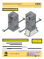 1
1
-
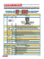 2
2
-
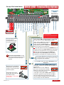 3
3
-
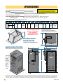 4
4
-
 5
5
-
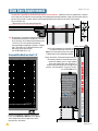 6
6
-
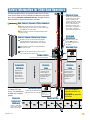 7
7
-
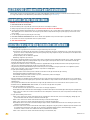 8
8
-
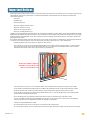 9
9
-
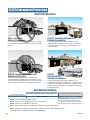 10
10
-
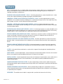 11
11
-
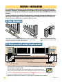 12
12
-
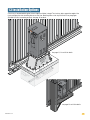 13
13
-
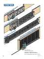 14
14
-
 15
15
-
 16
16
-
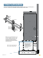 17
17
-
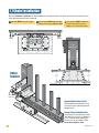 18
18
-
 19
19
-
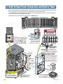 20
20
-
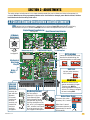 21
21
-
 22
22
-
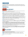 23
23
-
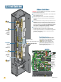 24
24
-
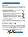 25
25
-
 26
26
-
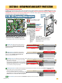 27
27
-
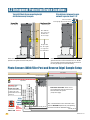 28
28
-
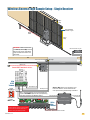 29
29
-
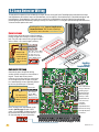 30
30
-
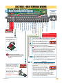 31
31
-
 32
32
-
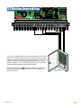 33
33
-
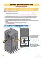 34
34
-
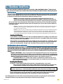 35
35
-
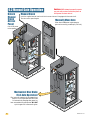 36
36
-
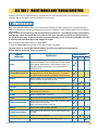 37
37
-
 38
38
-
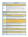 39
39
-
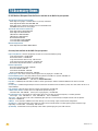 40
40
-
 41
41
-
 42
42


Ask a question and I''ll find the answer in the document
Finding information in a document is now easier with AI
Related papers
-
DKS 9200 Aug 2018 - later User manual
-
-
-
-
-
-
-
-
-
Other documents
-
Chamberlain LiftMaster MEGA SLIDE-X Owner's manual
-
Chamberlain LiftMaster Professional SW420 Installation guide
-
Merlin WingMate 4 Owner's manual
-
Nice Apollo Control Box Mini 120VAC MBAC1K User manual
-
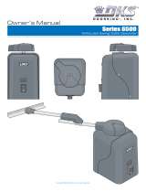 DKS Enterprises 6500 User manual
-
-
-
-
DoorKing 6006 User manual
-
LiftMaster SL585 User manual
