SPEEDI-VENT FD-12R8 20 Operating instructions

Type
Operating instructions
ADC
Flexible Duct Performance &
Installation Standards
(5
th
Edition)
The “Greenbook” of
Flex
Provides information about
Characteristics of flexible duct
Testing, Listing, Reporting,
and Certifying
Installation Requirements
Typical Accessories
General Commentary
Flexible Duct Types
(Non-Metallic Ducts)
Insulated
Non Porous Inner Core
Various types of Outer
Vapor Barriers
Insulated
Perforated Porous Inner Core
Various types of Outer
Vapor Barriers
Uninsulated
(Metallic Ducts)
Insulated
Metallic Inner Core
Various types of Outer Vapor Barriers
Uninsulated
Flexible Duct Types
Longitudinal Compression
of Flexible Duct
Compression causes increased pressure
drop:
15% = approximate 2 times
30% = approximate 4 times
45% = approximate 6 to 8 times
The moral of the story:
Ducts should be fully extended before
and during installation.
System has optimum air flow
- Minimizes pressure drop
- Maximizes savings
Goals:
1. Make it easy for the air to change direction.
2. Reduce overall “equivalent feet” of the duct run.
Key Point #4
Keep bends greater
than or equal to one
(1) duct diameter.
Minimize sagging and
“snaking” of the duct
runs.
90° = 20 equiv. ft.
180° offset = 40 equiv. ft.
45° = 10 equiv. ft.
So how do bends actually affect the air flow?
Examples
If duct is 8 feet long then the total
equivalent length = 28 feet.
For this installation the total
equivalent length is nearly
twice at approximately 50 feet.
Entrance & exit losses intentionally ignored for this
demonstration.
The total pressure drop for any duct run equals the sum of the fitting (or
bend) pressure drops and the pressure drop of the straight duct section.
Entrance fitting = 35 ft.
Total duct length = 14 ft.
2 x 45° bends (2 x 10’) = 20 ft.
1 x 90° bend (1 x 20’) = 20 ft.
Exit fitting = 35 ft.
Total Equivalent Length = 124 ft.
Proper Flexible Duct Connections
Sleeves used to connect 2 flex duct pieces
together shall be a minimum of 4 inches
in length and beaded on each end.
For non-metallic ducts, fittings shall be
beaded and have a minimum of 2 inches
collar length.
Use tapes or mastics listed to the UL181B Standard and marked “UL181B-
FX” for tape and “UL181B-M” for mastic.
If non-metallic straps are used, the straps should be listed to the UL181B
Standard and marked “UL181B-C”. Maximum pressure is limited to 6 inches
W.C. with non-metallic straps.
or
The
right
way to get
from here to there!!!!!!!
Using tape and fasteners to make connection
Cut completely through duct and wire
Fold back vapor barrier and insulation
Slide 1” of core over fitting and bead
Seal core to collar with 2 wraps of duct
tape
Secure connection with clamp placed
over the core and tape, past the bead
Pull vapor barrier and insulation back
over the core
Tape barrier with 2 wraps of duct tape
Flexible Duct Connection
(Non-Metallic)
Using tape and fasteners to make splice
Flexible Duct Splice
(Non-Metallic)
Cut completely through duct and wire
Fold back vapor barrier and insulation on
both ends
Slide 1” of each core over connecting
collar and beads
Seal cores to collar with 2 wraps of duct
tape
Secure each connection with clamp
placed over the core and tape, past the
bead
Pull vapor barrier and insulation back
over the core and overlap
Tape barrier with 2 wraps of duct tape
Flexible Duct Connection
(Non-Metallic)
Cut completely through duct and wire
Fold back vapor barrier and insulation
Apply mastic uniformly to the outside
surface of collar
Slide 1” of core over collar and past the
bead
Secure connection with clamp placed
over the core and past the bead
Pull vapor barrier and insulation back
over the core and fitting
Tape barrier with 2 wraps of duct tape
Using mastic and fasteners to make connection
Flexible Duct Splice
(Non-Metallic)
Cut completely through duct and wire
Fold back vapor barrier and insulation
on both ends
Apply mastic uniformly to both ends of
the connecting collar
Slide 1” of each core over connecting
collar and beads
Secure each connection with clamp
placed over the core, past the beads
Pull vapor barrier and insulation back
over the core and overlap
Tape barrier with 2 wraps of duct tape
Using mastic and fasteners to make splice
Using tape or mastic and screws to make a connection
Flexible Duct Connection
(Metallic)
Cut completely through duct and trim
edge
Fold back vapor barrier and insulation
When using mastic, apply uniformly to
collar
Slide 1” of core over fitting
Secure connection with #8 sheet metal
screws spaced equally around
circumference. Use 3 screws for
diameters under 12” and 5 for diameters
12” and over
When using tape (press. < 4”), seal core
to collar with 2 wraps of duct tape
Pull vapor barrier and insulation back
over the core
Tape barrier with 2 wraps of duct tape
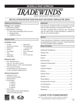
Using tape or mastic and sheet metal screws to make splice
Flexible Duct Splice
(Metallic)
Cut completely through duct and trim
edge
Fold back vapor barrier and insulation
on both ends
When using mastic, apply uniformly
both ends of the connecting collar
Slide 1” of core over connecting collar
Secure cores with #8 sheet metal screws
spaced equally around circumference.
Use 3 screws for diameters under 12”
and 5 for diameters 12” and over
When using tape (press. <4”), seal cores
together with 2 wraps of duct tape
Pull vapor barrier and insulation back
over the cores and overlap
Tape barrier with 2 wraps of duct tape
What material should I use to support flexible duct?
Per NFPA 90A and 90B, supplementary material used with air ducts shall meet
the requirements of Class 1 when tested to UL 723 (Surface Burn
Characteristic Testing), i.e. 25 Flame Spread & 50 smoke developed maximum.
Per ADC, any strapping material in contact with the flexible duct shall be 1-1/2
inch wide minimum and be applied at intervals not to exceed 4 feet (6 feet for
vertical supports). Sag should not exceed ½ inch per foot of support spacing.
Additional Points on Supporting Flex Duct
Ceiling joists or truss
supports used to support
flexible duct
Added supports before and after tight bends Added support to avoid damage by fitting
  • Page 1 1
  • Page 2 2
  • Page 3 3
  • Page 4 4
  • Page 5 5
  • Page 6 6
  • Page 7 7
  • Page 8 8
  • Page 9 9
  • Page 10 10
  • Page 11 11
  • Page 12 12
  • Page 13 13
  • Page 14 14
  • Page 15 15
  • Page 16 16
  • Page 17 17
  • Page 18 18

SPEEDI-VENT FD-12R8 20 Operating instructions

Type
Operating instructions

Ask a question and I''ll find the answer in the document

Finding information in a document is now easier with AI