Page is loading ...

Table of Contents 3/11/2020 CYL-LT-1MANUAL
Table of Contents Copyright 2020 Vestil Manufacturing Corp. 1 of 7
CYL-LT-1-HR & CYL-LT-1-PN Cylinder Lifts
Instruction Manual
Receiving Instructions
After delivery, remove the packaging from the product. Inspect the product closely to determine
whether it sustained damage during transport. If damage is discovered, record a complete description
of it on the bill of lading. If the product is undamaged, discard the packaging.
NOTE: The end-user is solely responsible for confirming that product design, use, and maintenance
comply with laws, regulations, codes, and mandatory standards applied where the product is used.
Technical Service & Replacement Parts
For answers to questions not addressed in these instructions and to order replacement parts,
labels, and accessories, call our Technical Service and Parts Department at (260) 665-7586. The
department can also be contacted online at http://www.vestilmfg.com/parts_info.htm
.
Electronic copies of Instruction Manuals
Additional copies of this instruction manual may be downloaded from
https://www.vestil.com/page-
manuals.php.
Vestil Manufacturing Co.
2999 North Wayne Street, P.O. Box 507, Angola, IN 46703
Telephone: (260) 665-7586 -or- Toll Free (800) 348-0868
Fax: (260) 665-1339
Web: www.vestilmfg.com e-Mail: [email protected]
Table of Contents
Specifications……………………………………..……………………………………………………………... 2
Signal Words….…………………………………………………………………………………………………. 2
Safety Instructions…………………………………………………………………………..………………….. 2
FIG. 1: CYL-LT-1-HR exploded view & bill of materials…………………………………………………..… 3
FIG. 2: CYL-LT-1-PN exploded view & bill of materials…………………………………………………..… 4
Using the Lifter…………………………………………………………………………………………………... 5
Record of Satisfactory Condition……………………………………………………………………………… 6
Inspections & Maintenance……………………………………………………..……………………………… 6
Labeling Diagram……...………………………………………………………….…………………………….. 6
Limited Warranty…...……..…………………………………………………………………………………….. 7

Table of Contents 3/11/2020 CYL-LT-1MANUAL
Table of Contents Copyright 2020 Vestil Manufacturing Corp. 2 of 7
SPECIFICATIONS
Dimensions, capacity, and net weight information appears in the following table:
a
SIGNAL WORDS
This manual uses SIGNAL WORDS to draw attention to uses of the product that could result in personal
injuries, as well as the probable seriousness of those injuries. Other signal words call attention to uses
likely to cause property damage. Signal words used in this manual appear below along with the definition of
each word.
Identifies a hazardous situation which, if not avoided, WILL result in DEATH or
SERIOUS INJURY. Use of this signal word is limited to the most extreme situations.
Identifies a hazardous situation which, if not avoided, COULD result in DEATH or
SERIOUS INJURY.
Identifies practices likely to result in product/property damage, such as operation that
might damage the product.
SAFETY INSTRUCTIONS
Vestil strives to identify all foreseeable hazards associated with the use of its products. However,
material handling is dangerous and no manual can address every conceivable risk. Ultimately, the most
effective way to prevent injury is to apply sound judgment whenever using this device.
Material handling is dangerous and could result in serious personal injuries or death.
• Read and understand the entire manual before using or servicing this lifter. DO NOT use this
device until you read and understand the entire instruction manual. Read the manual to refresh your
understanding of proper use and maintenance procedures.
• This lifting device must only be used by designated persons and lifting device inspectors.
Maintenance and test personnel should only use this device when necessary to perform their duties.
• DO NOT use this lifter if it is damaged, malfunctioning, or missing parts.
• DO NOT modify the product in any way without first obtaining written approval from Vestil.
Unapproved modifications automatically void the LIMITED WARRANTY and might make the product
unsafe to use.
• DO NOT exceed the capacity.
• DO NOT remove or obscure any label. Confirm the placement and legibility of all labels shown in the
LABELING DIAGRAM on p. 6. DO NOT use this device UNLESS all labeling is easily readable from a
reasonable distance.
• Inspect the lifter before each use. See INSPECTIONS AND MAINTENANCE on p. 6. If repairs are
necessary, only use manufacturer-approved replacement parts.
• DO NOT use the lifter to transport any cylinder that does not seat securely in the brackets. DO NOT
transport a cylinder unless it is securely held by the ratchet strap. The cylinder should not be able to slide
through the strap.
• ONLY raise the cylinder a few inches from the floor when transporting it. When transporting a cylinder up-
or-downhill, always remain uphill to the lifter. DO NOT move the lifter up or downhill unless you can easily
control the lifter. Although the CYL-HLT is equipped with 2 locking casters, these locks will NOT hold the
lifter in place on an incline and will not stop the lifter as it rolls downhill.
• DO NOT leave a raised cylinder unattended. ALWAYS lower the cylinder before leaving it.
• DO NOT store cylinders on the lifter. Unload the lifter and store cylinders in designated facilities.
Model Wheel type
Overall dimensions
(W X D x H)
Uniform
capacity
Net weight
CYL-LT-1-HR Hard rubber
18in. x 24in. x 80in.
46cm x 61cm x 203cm
300 lb.
136.4kg
97 lb.
44.1 kg
CYL-LT-1-PN Pneumatic
18in. x 24in. x 80in.
46cm x 61cm x 203cm
300 lb.
136.4kg
93 lb.
42.3 kg
W
D
H

Table of Contents 3/11/2020 CYL-LT-1MANUAL
Table of Contents Copyright 2020 Vestil Manufacturing Corp. 3 of 7
Item
Part no.
Description
Qty.
Item
Part no.
Description
Qty.
1
16-514-133 Weldment, base, upright 1
13
33008
Flat washer, low carbon,
USS, zinc plated,
3
/
8
”
5
2
16-527-008 Weldment, pulley assembly 1
14
99-027-005
Pulley,
3
/
16
” cable, 2
1
/
2
”
OD,
1
/
2
” ID
2
3
16-542-001 Assembly, winch and wire 1
15
11009
Hex bolt, gr. A, zinc
plated,
1
/
4
”-20 x 1
1
/
2
”
1
4
16-514-134 Weldment, strap height adjuster 1
16
37018
Nylon lock nut, gr. 2, zinc
finish,
1
/
4
”-20
5
5
16-525-033 Weldment, handle 1
17
65078
Extended prong cotter
pin, zinc finish,
1
/
8
”x 1
1
/
2
”
2
6
30-001-246
Strap, dual ratchet strap
1
18
13-025-037
Handle, black, 1” ID
2
7
16-112-019
Axle, CYL-D, BFSJ-KIT-A8.625
1
19
16-016-104
Bracket, handle, mounting
1
8
16-132-310 Wheel, 10” x 2.5”, 16mm steel hub 2
20
11019
Hex bolt, gr. A, zinc
plated,
1
/
4
”-20 x 4”
4
9
21-112-003 Pin,
1
/
2
” x 1
15
/
16
” retaining clevis 3
21
33004
Flat washer, USS, zinc
plated,
1
/
4
”
8
10
65077 Cotter pin, zinc plated,
1
/
8
” x 1
1
/
4
” 3
22
11119
Hex bolt, gr. A, zinc finish,
3
/
8
”-16 x 4”
2
11
11105
Hex bolt, gr. A, zinc-plated,
3
/
8
” –
16 x 1”
3
23
36106
Hex nut, gr. A, zinc
plated,
3
/
8
”-16
2
12
37024 Lock nut, Nylon insert,
3
/
8
”-16 3
24
33086
Flat washer, zinc plated,
SAE,
1
/
2
”-1.062” OD
8
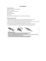
FIG. 1: CYL-LT-1-HR
Exploded Parts Diagram &
Bill of Materials
16-006-194

Table of Contents 3/11/2020 CYL-LT-1MANUAL
Table of Contents Copyright 2020 Vestil Manufacturing Corp. 4 of 7
Item
Part no.
Description
Qty.
Item
Part no.
Description
Qty.
1
16-514-133 Weldment, base, upright 1
13
11009
Hex bolt, gr. A, zinc plated,
1
/
4
”-20 x 1
1
/
2
”
1
2
16-527-008 Weldment, pulley assembly 1
14
37018
Nylon lock nut, gr. 2, zinc
finish,
1
/
4
”-20
5
3
16-542-001 Assembly, winch and wire 1
15
16-112-019
Axle, CYL-D, BFSJ-KIT-
A8.625
1
4
16-514-134 Weldment, strap height adjuster 1
16
65078
Extended prong cotter pin,
zinc finish,
1
/
8
”x 1
1
/
2
”
2
5
16-525-033
Weldment, handle
1
17
13-025-037
Handle, black, 1” ID
2
6
30-001-246
Strap, dual ratchet strap
1
18
16-016-104
Bracket, handle, mounting
1
7
21-112-003 Pin,
1
/
2
” x 1
15
/
16
” retaining clevis 3
19
16-132-276
Wheel, 10” x 3.5”,
pneumatic wheel for
5
/
8
”
axle
2
8
65077 Cotter pin, zinc plated,
1
/
8
” x 1
1
/
4
” 3
20
33004
Flat washer, USS, zinc
plated,
1
/
4
”
8
9
11105
Hex bolt, gr. A, zinc-plated,
3
/
8
” –
16 x 1”
3
21
11019
Hex bolt, gr. A, zinc plated,
1
/
4
”-20 x 4”
4
10
37024 Lock nut, Nylon insert,
3
/
8
”-16 3
22
11119
Hex bolt, gr. A, zinc finish,
3
/
8
”-16 x 4”
2
11
33008
Flat washer, low carbon, USS, zinc
plated,
3
/
8
”
5
23
36106
Hex nut, gr. A, zinc plated,
3
/
8
”-16
2
12
99-027-005 Pulley,
3
/
16
” cable, 2
1
/
2
” OD,
1
/
2
” ID 2
24
33086
Flat washer, zinc plated,
SAE,
1
/
2
”-1.062” OD
8
FIG. 2: CYL-LT-1-PN
Exploded Parts Diagram &
Bill of Materials
16-007-195

Table of Contents 3/11/2020 CYL-LT-1MANUAL
Table of Contents Copyright 2020 Vestil Manufacturing Corp. 5 of 7
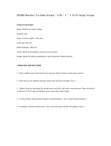
USING THE LIFTER [Refer to FIGS. 3A and 3B; CYL-LT-1-PN shown]
1. Adjust the position of the cylinder receiver to bring the top of the cylinder close to the angled arm of the
receiver.
2. Disconnect the strap hook at the end of the ratchet strap from the hook bolt.
3. Place a cylinder on the platform. Move the cylinder toward the mast until it rests against the cylinder
bracket.
4. If necessary, extend the strap so that it is long enough to wrap around the outside of the cylinder. To extend
the strap:
a. Pull the ratchet release toward the handle.
b. While holding up the release, pivot the handle approximately 180 degrees so that the ratchet
handle is in line with the ratchet base.
c. Pull on the strap to unwind it from the spindle. When enough strap has been unwound, let go of the
release lever.
5. Wrap the strap around the cylinder and connect the strap hook to the hook bolt.
6. Pivot the handle back and forth to tighten the strap against the cylinder.
7. Raise the cylinder just a few inches off of the ground by turning the winch handle. Transport the cylinder to the
desired location.
8. Before releasing the cylinder, be sure that it is fully and stably supported. Release strap tension by following
the procedure in step 4.
FIG. 3B: Wrap the ratchet strap around a cylinder and slide
the J-hooks into the J-hook slots on the back of the divider.
Strap
hook
Cylinder
receiver
Angled arm
of receiver
Ratchet
handle
Ratchet base
Ratchet
release
FIG. 3A: Noteworthy Features of Cylinder Lifter
(Model CYL-LT-1-PN shown)
Ratchet
strap
Hook bolt
Winch
Handle
Platform
Cylinder bracket
Mast

Table of Contents 3/11/2020 CYL-LT-1MANUAL
Table of Contents Copyright 2020 Vestil Manufacturing Corp. 6 of 7
RECORD OF SATISFACTORY CONDITION
Record the condition of the lifter before putting it into service. Thoroughly photograph the unit from
multiple angles. Include close range photos of all labeling, the cylinder receiver, the cable eyelet that
attaches the cable to the top of the receiver, fasteners (bolts, nuts), winch, platform, wheels, and welds.
Collate all photographs and writings into a single file. Mark the file appropriately to identify it. This file is
a record of the lifter in satisfactory condition. Compare the results of all inspections to this record to
determine whether the unit is in satisfactory condition. If the lifter is not in satisfactory condition, repair it
before returning it to service. Purely cosmetic changes, like damaged paint/powdercoat, do not
constitute changes from satisfactory condition. However, touchup paint should be applied to all affected
areas as soon as cosmetic damage occurs to prevent rusting and corrosion. If left unaddressed,
rusting/corrosion will alter the lifter from satisfactory condition and could make it unsafe to use.
INSPECTIONS AND MAINTENANCE
Inspections and repairs should only be performed by qualified persons. Compare the results of each
inspection to the RECORD OF SATISFACTORY CONDITION. Do not use the lifter unless all parts are
in satisfactory condition. Replace parts that are not in satisfactory condition before using the lifter
again. DON’T GUESS! If you have any questions about the condition of your lifter, contact the
TECHNICAL SERVICE
department. The phone number is provided on the cover page of this manual.
Never make temporary repairs of damaged or missing parts. Only use manufacturer-approved
replacement parts.
At least once per month:
• Examine the frame elements (mast, platform, handle, cylinder receiver) for cracked welds, metal
fatigue, rust, and corrosion that affect the structural integrity of the lifter. The structure should be clean,
square and rigid, and free of rust and corrosion. Remove dirt and debris.
• Inspect the winch and cable. Pulleys should roll smoothly as cable passes over them. The cable
should be free of elongations, bird-caging, thinned regions, and broken strands. The winch should turn
smoothly in both directions and ratchet normally. A brake should automatically apply whenever the
winch handle is stationary, i.e. the cylinder receiver should maintain position. The winch should be
solidly fastened to the frame of the lifter.
• Check the ratchet and ratchet strap. Confirm normal operation and condition. If either the strap or the
ratchet is damaged, tag the unit out of service and install manufacturer-approved replacement parts.
• Wheels. Confirm that each wheel rotates smoothly and is securely fastened to the lifter. The wheel
material should not be cracked, warped, dry rotted, etc.
• Labels: Confirm that every label shown in the LABELING DIAGRAM is in place, undamaged, and
easily readable from a reasonable distance.
B (Label 287)
A: Label 728
LABELING DIAGRAM
The unit should be labeled as shown
in the diagram. However, label content
and location are subject to change so
your product might not be labeled
exactly as shown. Replace all labels that
are damaged, missing, or not easily
readable (e.g. faded). To order
replacement labels, contact the technical
service and parts department online at
http://www.vestilmfg.com/parts_info.htm
.
Alternatively, you may request
replacement parts and/or service by
calling (260) 665-7586 and asking the
operator to connect you to the Parts
Department.
A
B

Table of Contents 3/11/2020 CYL-LT-1MANUAL
Table of Contents Copyright 2020 Vestil Manufacturing Corp. 7 of 7
LIMITED WARRANTY
Vestil Manufacturing Corporation (“Vestil”) warrants this product to be free of defects in material and
workmanship during the warranty period. Our warranty obligation is to provide a replacement for a defective,
original part covered by the warranty after we receive a proper request from the Warrantee (you) for warranty
service.
Who may request service?
Only a warrantee may request service. You are a warrantee if you purchased the product from Vestil or from
an authorized distributor AND Vestil has been fully paid.
Definition of “original part”?
An original part is a part used to make the product as shipped to the Warrantee.
What is a “proper request”?
A request for warranty service is proper if Vestil receives: 1) a photocopy of the Customer Invoice that
displays the shipping date; AND 2) a written request for warranty service including your name and phone
number. Send requests by one of the following methods:
US Mail Fax Email
2999 North Wayne Street, PO Box 507 Phone Enter “Warranty service request”
Angola, IN 46703 (260) 665-7586 in subject field.
In the written request, list the parts believed to be defective and include the address where replacements
should be delivered. After Vestil receives your request for warranty service, an authorized representative will
contact you to determine whether your claim is covered by the warranty. Before providing warranty service,
Vestil will require you to send the entire product, or just the defective part (or parts), to its facility in Angola,
IN.
What is covered under the warranty?
The warranty covers defects in the following original, dynamic parts: motors, hydraulic pumps, motor
controllers, and cylinders. It also covers defects in original parts that wear under normal usage conditions
(“wearing parts”), such as bearings, hoses, wheels, seals, brushes, and batteries.
How long is the warranty period?
The warranty period for original dynamic components is 90 days. For wearing parts, the warranty period is 90
days. Both warranty periods begin on the date Vestil ships the product to the Warrantee. If the product was
purchased from an authorized distributor, the periods begin when the distributor ships the product. Vestil
may, at its sole discretion, extend a warranty period for products shipped from authorized distributors by up to
30 days to account for shipping time.
If a defective part is covered by the warranty, what will Vestil do to correct the problem?
Vestil will provide an appropriate replacement for any covered part. An authorized representative of Vestil will
contact you to discuss your claim.
What is not covered by the warranty?
The Warrantee (you) is responsible for paying labor costs and freight costs to return the product to Vestil for
warranty service.
Events that automatically void this Limited Warranty.
• Misuse;
• Negligent assembly, installation, operation or repair;
• Installation/use in corrosive environments;
• Inadequate or improper maintenance;
• Damage sustained during shipping;
• Collisions or other accidents that damage the product;
• Unauthorized modifications: Do not modify the product IN ANY WAY without first receiving written
authorization from Vestil.
Do any other warranties apply to the product?
Vestil Manufacturing Corp. makes no other express warranties. All implied warranties are disclaimed to the
extent allowed by law. Any implied warranty not disclaimed is limited in scope to the terms of this Limited
Warranty. Vestil makes no warranty or representation that this product complies with any state or local
design, performance, or safety code or standard. Noncompliance with any such code or standard is not a
defect in material or workmanship.
/