Page is loading ...

18-GJ04D1-2
ALL phases of this installation must comply with NATIONAL, STATE AND LOCAL CODES
Important: This Document is customer property and is to remain with this unit. Please return to service information
pack upon completion of work.
These instructions do not cover all variations in systems
nor provide for every possible contingency to be met in
connection with the installation. Should further informa-
tion be desired or should particular problems arise which
are not covered sufficiently for the purchaser’s purposes,
the matter should be referred to your installing dealer or
local distributor.
Note: The manufacturer recommends installing ONLY
A.H.R.I. approved, matched indoor and outdoor systems.
Some of the benefits of installing approved matched
indoor and outdoor split systems are maximum efficien-
cy, optimum performance, and the best overall system
reliability.
Convertible Air Handlers
1-1/2 – 5 Ton
GAM5A0A18M11SAA
GAM5A0A24M21SAA
GAM5A0B30M21SAA
GAM5A0B36M31SAA
GAM5A0C42M31SAA
GAM5A0C48M41SAA
GAM5A0C60M51SAA
Note: Condensation may occur on the surface of the air
handler when installed in an unconditioned space. When
units are installed in unconditioned spaces, verify that
all electrical and refrigerant line penetrations on the air
handler are sealed completely.
The GAM5 air handlers will only use
the following internal electric heaters:
BAYEAAC05BK1AA
BAYEAAC05LG1AA
BAYEAAC08BK1AA
BAYEAAC08LG1AA
BAYEAAC10BK1AA
BAYEAAC10LG1AA
BAYEABC15BK1AA
BAYEABC20BK1AA
BAYEACC25BK1AA
Installer’s Guide

2
Table of Contents
Section 1. Safety Information. ......................................................................... 3
Section 2. Unit Design. ........................................................................................ 4
Section 3. Unit Preparation. ............................................................................. 6
Section 4. Optional Cabinet Disassembly. ............................................... 7
Section 5. Place Unit at Location. ............................................................... 12
Section 6. Unit Location Considerations. ............................................... 13
Section 7. Setting the Unit - Vertical Installation. ................................ 18
Section 8. Setting the Unit - Horizontal Installation. ......................... 20
Section 9. Connecting the Duct work. ...................................................... 21
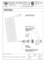
Section 10. Refrigerant Line. ......................................................................... 22
Section 11. Refrigerant Line Brazing. ....................................................... 23
Section 12. Condensate Drain Piping. ...................................................... 26
Section 13. Electrical - Low Voltage. .......................................................... 28
Section 14. Electrical - High Voltage. ......................................................... 33
Section 15. Time Delay Switch Adjustment. .......................................... 35
Section 16. Filters. ............................................................................................... 35
Section 17. Unit Outline Drawing. ............................................................... 36
Section 18. Start Up. ........................................................................................... 37
Section 19. Sequence of Operation. .......................................................... 39
Section 20. Checkout Procedures. ............................................................. 40
Note: Representative illustrations only included in this
document. Most illustrations display the upflow configu-
ration.

3
Section 1. Safety Information
▲
WARNING
!
SAFETY HAZARD! This information is intended for use
by individuals possessing adequate backgrounds of electrical and
mechanical experience. Any attempt to repair a central air condition-
ing product may result in personal injury and/or property damage.
The manufacturer or seller cannot be responsible for the interpreta-
tion of this information, nor can it assume any liability in connection
with its use.
LIVE ELECTRICAL COMPONENTS! During instal-
lation, testing, servicing, and troubleshooting of this product, it may
be necessary to work with live electrical components. Failure to fol-
low all electrical safety precautions when exposed to live electrical
components could result in death or serious injury.
▲
CAUTION
!
▲
WARNING
!
CORROSION HAZARD! To prevent shortening its service
life, the air handler should not be used during the finishing phases
of construction. The low return air temperatures can lead to the
formation of condensate. Condensate in the presence of chlorides
and fluorides from paint, varnish, stains, adhesives, cleaning com-
pounds, and cement creates a corrosive condition which may cause
rapid deterioration of the cabinet and internal components.
Important: Due to the unique design of this unit, which
allows the electrical wiring to be routed within the insula-
tion, do not screw, cut, or otherwise puncture the unit
cabinet in any location other than the ones illustrated in
this Installer Guide or in an approved accessory’s In-
staller Guide.
Important: Under no conditions should metal strapping
be attached to the unit to be used as support mecha-
nisms for carrying or suspension purposes.
SAFETY HAZARD! Sharp Edge Hazard. Be careful of sharp
edges on equipment or any cuts made on sheet metal while install-
ing or servicing. Personal injury may result.
▲
CAUTION
!
▲
CAUTION
!
HAZARDOUS VAPORS! Do not install an air handler
with a non-ducted return in the same closet, alcove, or utility
room as a fossil fuel device. Hazardous vapors can be distributed
throughout the conditioned space and equipment damage can
result.

4
Section 2. Unit Design
2.1 Cabinet Penetration
Screws can be drilled
into bottom of unit.
(1/2” max. screw length)
(Typical all sides)
Screws, saw cuts, and
other penetrations
are allowed in the
blower section for
installation of Side
Return Kit.
(Typical both sides)
Screws are allowed up to 3- 3/4”
from the top of the cabinet
(heater compartment).
(Typical both sides)
Screws for ange kit
attachment are allowed
along the interior of
the cabinet (see arrows)
(Typical all sides)
No penetrations
allowed.
(Typical all sides)
Screws allowed only in
the rst 3/4” of front
bottom of unit (in cross
member)
Important: Due to the unique design of this unit,
which allows the electrical wiring to be routed within
the insulation, do not screw, cut, or otherwise punc-
ture the unit cabinet in any location other than the
ones illustrated.
Important: Under no conditions should metal strap-
ping be attached to the unit to be used as support
mechanisms for carrying or suspension purposes.
2.2 Panel Removal
The unit contains four (4) access panels: Blower/Fil-
ter, Coil, Line Set, and Heater.
The Blower/Filter panel is removed using 1/4 turn
thumb screws.
1. Turn thumb screws on Blower/Filter panel.
2. Pull top of panel out, away from cabinet.
3. Lift panel up out of channel.
4. Set aside.

5
The Coil, Line Set, and Heater panels are removed
using Phillips head screws.
#3 Size Phillips
Coil and Heater panels must be removed prior to re-
moving the Line Set panel.
To remove Coil Panel:
1. Turn screws on Coil panel.
2. Pull bottom of panel out, away from cabinet.
3. Pull panel down and out of channel.
4. Set aside.
To remove Heater Panel:
1. Turn screws on Heater panel.
2. Pull panel straight out, away from cabinet.
3. Set aside.
Removal of the Line Set panel is required for all refrig-
erant line brazing and some condensate line assembly
depending on your orientation.
To remove Line Set panel:
1. Remove both Heater and Coil panels.
2. Turn screws on Line Set Panel.
2. Pull panel straight out, away from cabinet.
3. Set aside.

6
Section 3. Unit Preparation
3.1 Prepare The Unit For Installation
STEP 1 - Check for damage and report promptly to
the carrier any damage found to the unit.
Note: The unit is shipped “upside-down” in the
downflow orientation and may be easiest to trans-
port to the job site in that orientation. If the unit
must be transported in a horizontal position, it must
be laid on its back (marked “REAR” on carton).
Note: After the unit is removed from the carton,
depress the Schrader valve to verify coil is pressur-
ized.
3.2 Unit Accessories
Accessory Number Description Fits Cabinet Size
BAYEAAC05BK1A Electric Heater, 5kW, Breaker, 24V Control, 1 Ph A to C
BAYEAAC05LG1A Electric Heater, 5kW, Lugs, 24V Control, 1 Ph A to C
BAYEAAC08BK1A Electric Heater, 8kW, Breaker, 24V Control, 1 Ph A to C
BAYEAAC08LG1A Electric Heater, 8kW, Lugs, 24V Control, 1 Ph A to C
BAYEAAC10BK1A Electric Heater, 10kW, Breaker, 24V Control, 1 Ph A to C
BAYEAAC10LG1A Electric Heater, 10kW, Lugs, 24V Control, 1 Ph A to C
BAYEABC15BK1A Electric Heater, 15kW, Breaker, 24V Control, 1 Ph B to C
BAYEABC20BK1A Electric Heater, 20kW, Breaker, 24V Control, 1 Ph B to C
BAYEACC25BK1A Electric Heater, 25kW, Breaker, 24V Control, 1 Ph C
BAYSUPFLGA Supply Duct Flange A A
BAYSUPFLGBA Supply Duct Flange B B
BAYSUPFLGCA Supply Duct Flange C C
BAYRETFLGAA Return Duct Flange A A
BAYRETFLGB Return Duct Flange B B
BAYRETFLGCA Return Duct Flange C C
TASB175 Plenum Stand A A
TASB215 Plenum Stand B B
TASB235 Plenum Stand C C
BAYSRKIT100A Side Return Kit A to C
BAYICSKIT01A Internal Condensate Switch Kit A to C
BAYHHKIT001A Horizontal Hanger Kit A to C
BAYUVCLK001A UVC Lights A to C
BAYLVKIT100A Low Voltage Conduit Entry Kit A to C
Table 3.2

7
Note: The unit is shipped “upside-down” in the
downflow orientation and may be easiest to transport
to the job site in that orientation. If the unit must be
transported in a horizontal position, it must be laid
on its back (marked “REAR” on carton).
Note: To reassemble cabinet, follow the steps in
reverse order. Ensure electrical connections are
secure and the plug clips are engaged.
4.1 Disassemble cabinet for installation in tight areas or as needed.
Section 4. Optional Cabinet Disassembly
STEP 1 - Remove all four front panels. See Section
2.2.
Blower Electrical
Connections

8
Diverter
STEP 4 - Remove airflow diverter from the bottom of
coil drain pan by gripping the plastic diverter, using
your thumbs to spread the top of the diverter slightly
outwards, and then pulling down and out through the
blower opening as illustrated.
STEP 2 - Disconnect the two wiring connections
routed to the blower assembly.
STEP 3 - Slide Blower assembly out of unit using
built-in blower support channels and set aside.
Blower Support
Channel
Wiring
Connections

9
Coil Support
Channel
STEP 5 - Disconnect wires to the EEV motor and
sensors inside the coil assembly. Cut the wire ties
on those wire harnesses.
STEP 6 - Slide Coil assembly out of unit using built-
in coil support channels and set aside.
STEP 7 - Use a 5/16 Allen wrench on the locking
mechanism on each side of the bottom half of the
cabinet to loosen the locking mechanism. The locks
loosen by turning counter-clockwise approximately
3/4 of a turn.

10
1
2
STEP 8 - Lift the Coil section up and away from the
Blower section. Set aside.

11
STEP 9 - For extremely tight spaces where the
cabinet needs to be rotated through a small opening,
remove the top panel and all cross members. Use a
manual driver to avoid stripping screw holes.
Note: Cross Members are removed by rotating them
toward the door opening and then lifting up and out
of the unit.
STEP 10 - Continue preparation by following the
proper carrying procedures shown in Section 5.
1
2

12
STEP 1 - Carry the unit to the installation location.
STEP 2 - Reassemble by reversing the steps listed in
Section 4 if disassembly was required.
Important: Under no conditions should metal strap-
ping be attached to the unit to be used as support
mechanisms for carrying or suspension purposes.
Approved carrying:
1. Hold by the cross members within the cabinet
or unit top plate and use as handles for lifting
and carrying the coil and blower sections.
Cross Members
Cross Member
Unit Top Plate
Section 5. Place Unit at Location
5.1 Carry Unit

13
2. Slip a flexible strap through both of the side
electrical conduit entry points and use the flex-
ible strap to lift and carry the coil section of the
unit.
Flexible strap
Section 6. Unit Location Considerations
6.1 Unit Dimensions and Weight
Model
Number
H x D x W
in.
*Blower
Compartment
in.
Unit
Net Weight
lbs.
GAM5A0A18H21SAA 50 x 22 x 17 1/2 22 120
GAM5A0A24H21SAA 50 x 22 x 17 1/2 22 120
GAM5B0A30H31SAA 52 x 22 x 21 22 133
GAM5B0A36H31SAA 56 x 22 x 21 22 143
GAM5C0A42H41SAA 57 x 22 x 23 1/2 22 158
GAM5C0A48H41SAA 62 x 22 x 23 1/2 22 174
GAM5C0A60H51SAA 62 x 22 x 23 1/2 22 178
*Subtract from total height to get Coil and Heater compartment height.
Table 7.1
D
H
W

14
To place the unit in the configuration your application requires (upflow, downflow, horizontal right, or horizontal left),
simply turn the unit to that orientation.
Note: The air handlers are shipped from the factory suitable for four-way conversion. They are shipped in the down-
flow orientation.
6.2 Four-Way Conversion
Upflow
Condensate
Drains
Refrigerant
Connections
Downflow
Condensate
Drains
Downflow Configuration
(as shipped)
Refrigerant
Connections
Airflow
Upflow Configuration
Low Voltage
Connections
inside unit
Low Voltage
Connections
inside unit
Airflow
Control
Pocket
Inside unit
Control
Pocket
Inside unit

15
Horizontal Right Configuration
Refrigerant
Connections
Horizontal Left
Condensate
Drains
Low Voltage
Connections
inside unit
Refrigerant
Connections
Horizontal Left Configuration
Low Voltage
Connections
inside unit
Horizontal Right
Condensate Drains
Airflow
Airflow
Control
Pocket
Inside unit
Control
Pocket
Inside unit

16
6.3 Non Ducted Applications
Non-Ducted Return Installations:
Installation in a closet, an alcove, or a utility •
room without a return duct requires the use
of a plenum accessory kit as it uses the area
space as a return air plenum. Minimum clear-
ances to combustible materials and service
access must be observed (see outline draw-
ing).
This area may also be used for other purpos- •
es, including an electric hot water heater, but
in no case shall a fossil fuel device be installed
and/or operated in the same closet, alcove, or
utility room.
Review local codes to determine limitations if •
the unit is installed without a return air duct.
Ducted Return
Non-Ducted
Return
Supply Duct
Plenum
Accessory
with safety guard
▲
CAUTION
!
HAZARDOUS VAPORS! Do not install an air handler
with a non-ducted return in the same closet, alcove, or utility
room as a fossil fuel device. Hazardous vapors can be distributed
throughout the conditioned space and equipment damage can
result.
Ducted Return Installations:
Installation in an attic, garage, or crawl space with •
ducted supply and return air is appropriate. Minimum
clearances to combustible materials and service ac-
cess must be observed (see outline drawing).
6.4 Ducted Applications
Supply Duct
Return Duct

17
6.5 Additional Unit Preparation Considerations
For proper installation the following items must be con-
sidered prior to moving the unit to its installation site:
Pursuant to Florida Building Code 13-610.2.A.2.1, this •
unit meets the criteria for a factory sealed air handler.
If a side return is needed for your application, the side •
return MUST be prepared prior to moving the air han-
dler to its installation location. See the Side Return Kit
# BAYSRKIT100A Installer Guide for detailed instruc-
tions.
Study the unit’s outline drawing and dimensions prior •
to selecting the installation site. Note in advance
which electrical conduit entry points and condensate
drain holes are to be used, so that proper clearance
allowances can be made for installation and future
maintenance.
Installation of the air handler must be made prior to, •
or at the same time as, the installation of the outdoor
unit in order to allow access for refrigerant lines.
Consider the overall space needed when external •
accessories are used, additional height and width
requirements may exist.
These units are not approved for outdoor installation. •
These units must be installed in the proper air flow •
direction.
Any third-party heater accessories, including •
hydronic coils and duct heaters must be downstream
of the unit.
Note: No atomizing style humidifier is allowed in the •
return plenum with the use of this unit.
Excessive bypass air may cause water blow-off, •
which will adversely affect system operation and air
cleaner performance. To verify bypass airflow, fol-
low the Bypass Humidifier Pre-Installation Checkout
and Set-Up Procedures available through your local
distributor. Ask for publication number 18-CH37D1-*
Steam and Flow-through Fan Power Duct-mounted
Humidifiers. Follow the humidifier installation instruc-
tions. These should only be installed on the supply
air side of the system.
Note: The air handlers have been evaluated in accor-
dance with the Code of Federal Regulations, Chapter
XX, Part 3280 or the equivalent. “SUITABLE FOR
MOBILE HOME USE.”

18
Section 7. Setting the Unit - Vertical Installation
7.1 Considerations
Provide a minimum height of 14 inches for proper
unrestricted airflow below the unit. Allow a minimum
of 21 inches clearance in front of the air handler to
permit maintenance and removal of filter.
Position unit on suitable foundation. If a manu- •
facturer approved accessory is not used, a frame
strong enough to support the total weight of the
unit, accessories, and duct work must be provided.
Isolate unit from the foundation using a suitable •
isolating material.
Typical Closet Installation
7.2 Upflow Installation
TASB Installation
1. Assemble the TASB using the TASB’s Installer
Guide.
TASB accessories can be purchased from:
Miami Tech Inc.
3611 NW 74 Street
Miami, FL 33147
Phone: 800-339-2290
Fax: 305-693-6152
www.miamitech.com
TASB175 for use with 17.5” cabinets
TASB215 for use with 21.5” cabinets
TASB235 for use with 23.5: cabinets
Typical TASB Installation
Airflow
AirflowAirflow

19
Plenum Installation
1. Assemble the plenum using the plenum’s
Installer Guide.
Typical Plenum Installation
Airflow
7.3 Downflow Installation
Downflow installation must comply with national, •
state, and local codes.
The air handlers are rated for zero clearance from •
combustible materials.
STEP 1 - Prepare the location site as appropriate for
your application and per national, state, and local code
requirements.
STEP 2 - Set the unit in position.
Representative Illustration
Typical Downflow Installation
On units with sheet metal returns: Return plenum
must be flanged. Sheet metal drill point screws
must be 1/2” in length or shorter.

20
8.2 Considerations
STEP 1 - Support the unit from the bottom (near both
ends). The service access must remain unobstructed.
Important: The unit can only be supported from the
bottom. Do not drill or screw supports into any area
of the cabinet.
Note: Do not allow the unit to be used as strain relief.
Approved bottom support methods are rails, u- •
channels (Unistrut®), or other load bearing materi-
als.
The unit must be isolated carefully to prevent •
sound transmission. Field supplied vibration isola-
tors are recommended.
STEP 2 - Install an auxiliary drain pan under the
horizontal air handler to prevent possible damage to
ceilings.
Isolate the auxiliary drain pan from the unit and •
from the structure.
Connect the auxiliary drain pan to a separate drain •
line and terminate according to local codes.
Important: Due to the unique design of this unit,
which allows the electrical wiring to be routed within
the insulation, do not screw, cut, or otherwise puncture
the unit cabinet in any location other than the ones
illustrated in this Installer Guide or in an approved ac-
cessory’s Installer Guide.
Important: Under no conditions should metal strap-
ping be attached to the unit to be used as support
mechanisms for carrying or suspension purposes.
Field Supplied
Isolators
Auxiliary Drain
Pan
Bottom Support
Near Both Ends
Section 8. Setting the Unit - Horizontal Installation
8.1 Secure Coil (Horizontal Applications Only)
STEP 1 - Remove Coil Panel.
STEP 2 - Remove screw from documentation packet.
STEP 3 - While the air handler is in the upflow posi-
tion, use the supplied screw to secure the coil seal
plate to cross member as shown.
Important: The Coil Seal Plate and screw secure the
coil in the center of the air handler. Failure to follow
these steps can prevent the Coil Panel from being eas-
ily replaced on the unit.
/