Simplicity MOWER, BILLY GOAT Owner's manual

Category
Garden tools
Type
Owner's manual

This manual is also suitable for

P/N 520144
Part No 520187 (A)
Form No F061207C
1
FM Owner’s Manual
BILLY GOAT FINISH MOWER
Owner's Manual
FM3301 & FM3301E
Patent Number: D494985
Accessories
Mulching Kit
Reduces lawn
clippings to fine
nutrient-rich
particles that filter
down to the soil.
Grass Catcher Kit
Easily convert your
mower to bag
grass and leaves.
P/N 520142
Transaxle Guard
Kit
To protect the
transaxle from
accidental contact
from concrete
curbs or other
hazards.
P/N 520155
Not for Reproduction
Part No 520187 Form No F061207C
2
FM Owner’s Manual
ABOUT THIS MANUAL
THANK YOU for purchasing a BILLY GOAT
®
FM Mower. Your new machine has been carefully designed and
manufactured to provide years of reliable and productive service. This manual provides complete operating and
maintenance instructions that will help to maintain your machine in top running order. Read this manual carefully
before assembling, operating, or servicing your equipment.
CONTENTS
SERIAL PLATE DATA AND SPECIFICATIONS 3
GENERAL SAFETY 4 -5
SOUND AND VIBRATION 6
INSTRUCTION LABELS 7
PACKING CHECKLIST 8
ASSEMBLY 9
OPERATION 10-12
MAINTENANCE 13-16
TROUBLESHOOTING AND WARRANTY PROCEDURE 17
ILLUSTRATED PARTS & PARTS LISTS 18-25
ACCESSORIES 26
MAINTENANCE RECORD 27
Not for Reproduction
Part No 520187 Form No F061207C
3
FM Owner’s Manual
SERIAL PLATE DATA
Record the model number, serial number, date of
purchase, and where purchased.
Purchase Date:
Purchased From:
Specifications
FM3301 FM3301E
Engine: HP 13 (9.7 kW) 13 (9.7 kW)
Engine: Model 21A9020149 21A9070147
Engine: Type B & S INTEK OHV B & S INTEK OHV Elec.
Engine: Fuel Capacity 3.0 qt. (2.8 L) 3.0 qt. (2.8 L)
Engine: Oil Capacity 1.5 qt. (1.4 L) 1.5 qt. (1.4 L)
Total Unit Weight: 267# (121 Kg) 267# (121 Kg)
Max. operating slope 15
o
15
o
Overall length 57” (1.44m) 57” (1.44m)
Overall width 43” (1.09m) 43” (1.09m)
Overall height 47” (1.19m) 47” (1.19m)
In accordance with 2000/14/EEC 108dBa 108dBa
Sound at operators position 88dBa 88dBa
Vibration at operator position 2.65g 2.65g
Not for Reproduction
Part No 520187 Form No F061207C
4
FM Owner’s Manual
GENERAL SAFETY INSTRUCTIONS and SYMBOLS
The safety symbols shown below are used throughout this manual. You should become familiar with them before
assembling, operating, or servicing this equipment.
This symbol indicates important information that will prevent injury to yourself or others.
This symbol indicates ear protection is recommended when operating this equipment.
This symbol indicates eye protection is recommended when operating this equipment.
This symbol indicates gloves should be worn when servicing this equipment.
This symbol indicates that this manual and the engine manufacturer’s manual should be read
carefully before assembling, operation, or servicing this equipment.
This symbol indicates important information that will prevent damage to your BILLY GOAT
®
FM Mower.
This symbol indicates the engine oil level should be checked before operating this
equipment.
Read and make sure you thoroughly understand the following safety precautions before assembling, operating or
servicing this equipment:
READ this manual and the engine manufacturer’s manual carefully before assembling,
operating, or servicing this equipment.
EAR PROTECTION is recommended when operating this equipment.
EYE PROTECTION is recommended when operating this equipment.
BREATHING PROTECTION is recommended when operating this equipment.
EXHAUST from this product contains chemicals known to the State of California to cause
cancer, birth defects or other reproductive harm.
DO NOT operate this equipment on any unimproved forested, brushy, or grass covered land
unless a spark arrester is installed on the muffler as required by Section 4442 of the
California Public Resources Code. The arrester must be maintained in good working order.
Other states may have similar laws. Federal laws apply on federal lands.
DO NOT run engine in an enclosed area. Exhaust gases contain carbon monoxide, an
odorless and possibly fatal poison.
Not for Reproduction
Part No 520187 Form No F061207C
5
FM Owner’s Manual
WARNING: IMPORTANT! This cutting machine is capable of amputating hands and feet and throwing objects.
Failure to observe the following safety instructions could result in serious injury or death.
DO NOT run this equipment indoors or in any poorly ventilated area. Refueling outdoors is recommended.
DO NOT refuel this equipment while the engine is running. Allow engine to cool for at least two minutes before
refueling.
DO NOT store gasoline near an open flame.
DO NOT remove gas cap while engine is running.
DO NOT start or operate engine if strong odor of gasoline is present.
DO NOT start or operate engine if gasoline is spilled. Move equipment away from spill until gasoline has completely
evaporated.
DO NOT smoke while filling the fuel tank.
DO NOT check for spark with spark plug or spark plug wire removed. Use an approved spark tester.
DO NOT operate engine without a muffler. Inspect muffler periodically and replace if necessary. If equipped with
muffler deflector, inspect deflector periodically and replace if necessary.
DO NOT operate engine with grass, leaves or other combustible material near the muffler.
DO NOT touch muffler, cylinder, or cooling fins when hot. Contact with hot surfaces may cause severe burns.
DO NOT leave equipment unattended while in operation.
DO NOT park equipment on a steep grade or slope.
DO NOT operate equipment with bystanders in or near the work area.
DO NOT allow children to operate this equipment.
DO NOT operate equipment with guards removed.
DO NOT operate equipment near hot or burning debris or any toxic or explosive materials.
DO NOT operate equipment on slopes greater than specified in Specifications section of this manual.
DO NOT operate barefoot or wearing open sandals. Always wear substantial footwear
DO NOT place hands or feet underneath unit, or near any moving parts.
DO NOT pull mower backwards unless absolutely necessary
DO NOT operate the mower while under the influence of alcohol or drugs.
DO NOT operate mower in wet grass. Always be sure of your footing; keep a firm hold on the handle and walk; neve
r
run.
DO NOT mow on wet grass. Reduced footing could cause slipping.
DO NOT mow near drop-offs, ditches, or embankments. The operator could lose footing or balance
DO NOT mow excessively steep slopes.
DO NOT change the engine governor setting or overspeed the engine.
ALWAYS Stop the blade(s) when crossing gravel drives, walks, or roads.
ALWAYS Shut the engine (motor) oft and wait until the blade comes to complete stop before removing grass catcher.
ALWAYS Mow only in daylight or good artificial light.
ALWAYS Disengage the self-propelled mechanism or drive clutch on mowers so equipped before starting the engine.
ALWAYS wear safety goggles or safety glasses with side shields
ALWAYS remove spark plug wire when servicing equipment to prevent accidental starting.
ALWAYS check fuel lines and fittings frequently for cracks or leaks. Replace if necessary.
ALWAYS store fuel in approved safety containers.
WARNING: Important
Remove all rocks, wire, string, etc. that can present a hazard during work prior to starting.
DO identify and mark all fixed objects to be avoided during work such as sprinkler heads, water valves, limbs, or
clothes line anchors, etc.
Not for Reproduction
Part No 520187 Form No F061207C
6
FM Owner’s Manual
SOUND
SOUND LEVEL 88 dB(a) at Operator Position
108 dB(a)
Sound tests were conducted in accordance with 2000/14/EEC, and were performed on 8-15-2003 under the
conditions listed below.
Sound power level listed is the highest value for any model covered in this manual. Please refer to serial plate on
the unit for the sound power level for your model.
VIBRATION DATA
VIBRATION LEVEL 2.65g (25.20m/s
2
)
Vibration levels at the operator’s handles were measured in the vertical, lateral and longitudinal directions using
calibrated vibration test equipment. Tests were performed on 5-26-2006 under the conditions listed below.
INTENDED USE
INTENDED USE: This unit is mainly designed for cutting grass. Some overgrown weeds, and taller grass may also
be cut. Be sure to inspect work area and machine before operating. Make sure that all operators of this equipment
are trained in general machine use and safety.
General Conditions: Sunny
Temperature: 86
o
F (30
o
C)
Wind Speed: 2.4 mph (3.9 kmh)
Wind Direction: South
Humidity: 57%
Barometric Pressure: 30.2Hg (767 mm Hg)
General Conditions: Sunny
Temperature: 87.44
o
F (30.8
o
C)
Wind Speed: 3.1 mph (5.04kph)
Wind Direction: South East
Humidity: 41.5%
Barometric Pressure: 29.89Hg (101.25kpa
)
Not for Reproduction
Part No 520187 Form No F061207C
7
FM Owner’s Manual
INSTRUCTION LABELS
The labels shown below were installed on your BILLY GOAT
®
FM Mower. If any labels are damaged or missing, replace them before operating
this equipment. Item numbers from the Illustrated Parts List and part numbers are provided for convenience in ordering replacement labels. The
correct position for each label may be determined by referring to the Figure and Item numbers shown.
LABEL DANGER KEEP HANDS LABEL PATENT FM DANGER FLYING DEBRIS LABEL CLUTCH BLADE LABEL CLUTCH DRIVE
AND FEET AWAY ITEM#178 P/N520191 ITEM #2 P/N 810736 ITEM #11 P/N 500177 ITEM #10 P/N 500176
ITEM #5 P/N 400424
LABEL WARNING GUARDS LABEL EXPLOSIVE FUEL LABEL CUTTING HEIGHT LABEL WARNING MOWER
ITEM #119 P/N 900327 ITEM #4 P/N 400268 ITEM #95 P/N 520117 ITEM #17 P/N 510206
LABEL HEIGHT ADJUST GUIDELINE LABEL EAR EYE BREATHING LABEL READ MANUAL
ITEM #7 P/N 520043 ITEM #114 P/N 890254 ITEM #52 P/N 890301
ENGINE LABELS
THROTTLE CONTROLS AND LABELS
BRIGGS AND STRATTON
Throttle Control SPEED CONTROL
5th gear (Transporting Speed): Lift up
on the lever then push to engage in
the 5th gear.
Rev: Lift up on the lever then pull back
for reverse.
Electric Start Only
Pull up on the switch then push
forward to start the en
g
ine.
LABEL FM
CONSOLE ITEM #47
P/N 520079
ELECTRIC (520048)
Not for Reproduction
Part No 520187 Form No F061207C
8
FM Owner’s Manual
PACKING CHECKLIST
Your Billy Goat Mower is shipped from the factory in one crate, completely assembled except for the
handles and console assembly.
PUT OIL IN ENGINE BEFORE STARTING
READ all safety instructions before assembling unit.
TAKE CAUTION
when removing the unit from the box.
Boxing Parts
Checklist
Briggs and
Stratton 6HP
Literature Assy
P/N-520137
PARTS BAG &
LITERATURE ASSY
Warrant
y
card P/N- 400972
,
Owner’s Manual P/N-520187.
Ty-wrap 900407 qty. 4
8041051 qty. 4
Clevis pin 520119 qty. 1
Roll pin 1/4"x1" long
520156 qty. 1
Washer 3/8 FC
8171004 qty. 4
Washer split lock 3/8"
8177012 qty. 4
Washer 5/16" FC
8171003 qty. 2
Pal Nut 3/8" 360218
qty. 1
Parts Bag
Not for Reproduction
Part No 520187 Form No F061207C
9
FM Owner’s Manual
ASSEMBLY
NOTE: All item numbers called out in the assembly, operation,
and maintenance sections of this manual can be found on Parts
List (pages 15-18).
1. Cut and remove the nylon retaining straps (see figure 11-1).
2. With the console and handle assembly positioned as shown in
Figure 11-3, insert the shift linkage rod (Item 31) into the shift
linkage connector (Item 54).
3. To assemble the shift rod (item 31) to the shift linkage (item 54),
use the roll pin in the parts/literature bag. If you’ll notice on the
shift linkage, the hole is larger on one side than the other.
It will be easier to start the roll pin from the larger side, forcing it
through the shift rod and the hole on the other side of the shift
linkage, using a hammer or large adjustable pliers.
4. Insert one of the handle mounting bolts (Item 102) with split lock
washer (Item 6) on top of flat washer (Item 184) through the rear
handle mounting hole of the right side handle, and screw it into the
rear handle mounting hole on the right side of engine base
chassis (Item 61). Repeat this procedure for the left side using the
left handle.
5. On each side of the mower, insert one of the handle mounting
bolts (Item 102) with split lock washer (Item 6) on top of flat
washer (Item 184) through the hole in one end of the handle brace
(Item 32), the front handle mounting hole of the handle and screw
into the front handle mounting hole in the engine base chassis
(Figure 11-5).
7. Position control cables and use 2 cable ties on each handle to
secure the cables in position. The top cable tie should be 1” below
the console and the lower tie should be 12” below the console
(see figure 11-8 and 11-9).
8. Check the position of the shift rod guide (Item 69), and if
necessary, snap it in place in the shift bracket (Item 78) as shown
in Figure 11-10.
9. Put shift lever in NEUTRAL, depress the brake lever (release
the brake) and carefully pull the machine back off the pallet.
10. Fill with oil and gas to the proper level and the unit is ready to
mow. (A battery will also have to be installed on electric models.)
11. Read the operator’s manual.
Fig. 11-1
Fig. 11-3
Fig. 11-4 Fig. 11-5
Fig. 11-7
Fig. 11-10 Fig. 11-9Fig. 11-8
Shift rod
Shift
linkage
Roll Pin
Cable
ties
Not for Reproduction
Part No 520187 Form No F061207C
10
FM Owner’s Manual
OPERATION
Like all mechanical tools, reasonable care must be used when operating machine.
Inspect machine work area and machine before operating. Make sure that all operators of this
equipment are trained in general machine use and safety.
PUT OIL IN ENGINE BEFORE STARTING
STARTING
ENGINE: See engine manufacturer’s instructions for type and amount of oil and gasoline used. Engine
must be level when checking and filling oil and gasoline.
ENGINE SPEED: Controlled by throttle lever on the control console plate.
FUEL VALVE: Move fuel valve to "ON" position (when provided on engine).
CHOKE: Operated with the throttle control by moving the throttle control to the full start position.
THROTTLE: Move remote throttle control to fast position. Pull starting rope to start engine.
ELECTRIC START: Choke the engine if necessary. Pull up then push forward on the toggle switch until
engine starts, then release switch to run.
1. Select desired cutting height before starting engine.
2. Be sure drive lever or blade lever are not engaged.
3. Choke if necessary.
4. Pull back on starter rope slowly until resistance is felt. Then pull cord rapidly to start. Repeat if necessary.
Do not operate if excessive vibration occurs. If excessive vibration occurs, shut engine off immediately and check for
damaged or worn blade, loose blade jam nut, loose engine or lodged foreign objects. Note: See maintenance section
for proper blade jam nut torque specifications.
HANDLING & TRANSPORTING:
Using two people to lift machine is recommended. Lift holding the handle and front of deck. Secure in place
during transport.
Never lift the machine while the engine is running. ENGINE MUST BE OFF while handling, lifting, or
transporting the unit on or off the vehicle.
STORAGE
Never store engine indoors or in enclosed poorly ventilated areas with fuel in tank, where fuel fumes may reach
an open flame, spark or pilot light, as on a furnace, water heater, clothes dryer or other gas appliance.
If engine is to be unused for 30 days or more, prepare as follows:
Be sure engine is cool. Do not smoke. Remove all gasoline from carburetor and fuel tank to prevent gum
deposits from forming on these parts and causing possible malfunction of engine. Drain fuel outdoors, into an
approved container, away from open flame. Run engine until fuel tank is empty and engine runs out of gasoline.
NOTE: Fuel stabilizer (such as Sta-Bil) is an acceptable alternative in minimizing the formation of fuel gum deposits
during storage. Add stabilizer to gasoline in fuel tank or storage container. Always follow mix ratio found on
stabilizer container. Run engine at least 10 min. after adding stabilizer to allow it to reach the carburetor.
CAUTION: Wheels must be chocked or blocked when unit is parked on a slope.
Not for Reproduction
Part No 520187 Form No F061207C
11
FM Owner’s Manual
CUTTING OPERATION
CAUTION: Shut off the blades when crossing gravel drives, walks or roads
and under all conditions where thrown objects might be a hazard.
CLEARING A CLOGGED CUTTING DECK: Turn engine off and wait for
blade to stop completely. Disconnect spark plug wire.
Wearing durable gloves, remove clog. Danger, the clog may contain
sharp materials. Reconnect spark plug wire.
CAUTION: Use extreme care when operating the blades. Inspect the work
area for foreign objects that could cause damage to the unit or injure the
operator if struck by the blade. Never operate the blades with bystanders in the
work area.
GENERAL OPERATION: To engage the blades, depress the operator’s left
hand control lever against operator’s handle. The blade is disengaged by
releasing this lever. (See Fig. 1.1) To engage the wheel drive press down on
the brake lever, lift the operator’s right hand control lever against operator’s
handle. The drive is disengaged by releasing this lever.(See Fig. 1.2) Ground
speed can be varied by shifting gears as described on page 12. To begin
cutting, engage the blade lever, allow the blade to spin up to speed, and
engage the wheel drive to begin moving forward into the material to be cut.
NOTE: Do not engage blades during transport between work sites. The blade
should remain disengaged at all times when work is not being performed.
The best performance is achieved when cutting in dry conditions. If the deck
becomes choked with grass or debris during operation, back unit off of debris
allowing machine to clear itself and continue cutting, or shut the unit off and
clear the clog by hand (See above). A drop in engine RPM or a noticeable
change in engine sound is usually a good indicator of a clogged discharge or
other interference.
Under most conditions cutting should be done in second or third gear. Fourth
gear should be reserved for conditions where grass is thinned out or not as tall.
The quality of the cut produced is directly related to the unit's ground speed
during cutting. If the quality of the cut is not satisfactory (i.e. material left
standing) you should shift into a lower gear during cutting. For improved control
in confined areas, this machine can be pushed forward or backward by
releasing the drive lever and shifting to neutral located at the bottom of the
operator's right-hand handle while depressing the brake release
lever.
Fig. 16-2
Fig. 16-1
Fig. 16-3
Fig. 16-4
CUTTING HEIGHT ADJUSTMENT
CAUTION: DO NOT make cutting height adjustment when engine is running.
Cutting height can be adjusted from 1.5" to 4" by placing spacers above or below
caster spindles. For easiest adjustment change the height on one side at a time.
To change cutting height, tilt the unit back, remove lynch pin, remove all spacers
then set if off to the side, remove caster rig, add or subtract spacers, reinstall
caster rig, place remainder of spacers if any, then reinsert lynch pin (see figure
16-1 through 16-4). Repeat this step on other side.
NOTE: Be sure that the spacers are even on both casters. Running the deck out
of level will result in poor cut quality and increased belt wear.
Not for Reproduction
Part No 520187 Form No F061207C
12
FM Owner’s Manual
PROPULSION
This unit is self-propelled, and is controlled by an operator presence control. To
engage the wheel drive, first push down on the BRAKE RELEASE lever on the
right side, and then lift the operator's DRIVE lever on the right side against
operator's handle. The drive is disengaged by releasing the lower lever. (See
figure 16-6). Shift to neutral, push and hold the Brake lever to free wheel.
GROUND SPEED can be varied by selecting a higher or lower gear using the
gearshift lever on top of the console (see figure 16-7). Note: Only change gear
selection when unit is stopped. Under most conditions cutting should be done in
second or third gear. Fourth gear should be reserved for conditions where grass
is thinned out or not as tall. The quality of the cut produced is directly related to
the unit's ground speed during cutting. If the quality of the cut is not satisfactory
(i.e. material left standing), you should shift into a lower gear during cutting. For
improved control in confined areas, this machine can be pushed forward or
backward by releasing the drive lever located at the bottom of the operator's
right-hand handle, and shifting to neutral while depressing the brake release
lever.
HILLSIDE MOWING
WARNING! Never mow on any slope greater than 15 degrees. Always
mow across the face of slopes; never up and down or diagonally (see figure
16-8). DO NOT attempt sudden starts or stop when mowing on a slope.
Avoid sudden turns and use extreme caution when changing direction on a
slope.
BLADE CLUTCH
The FM mower blade clutch is controlled by an operator presence control. To
engage the blade, depress the operator’s left hand control lever against
operator’s handle. The blades are disengaged by releasing this lever. (See figure
16-5)
NOTE: The blade clutch must be either fully engaged for cutting or fully
disengaged to bring the blades to a stop. Do not operate the unit with the blade
clutch partially engaged. Premature belt wear and clutch failure will result from
improper operation of the clutch.
CAUTION: Use extreme care when operating the blades. Inspect the work
area for foreign objects that could cause damage to the unit or injure the operator
if struck by the blade. Never operate the blades with bystanders in the work
area. Lever operates the blade without either the discharge deflector chute or the
grass catcher in place.
Fig. 16-5
Fig. 16-6
Fig. 16-7
Fig. 16-8
Blade Clutch Lever
Operator’s
handle
Brake release lever
-down to release
Operator’s
handle
Drive lever
-up to drive
Not for Reproduction
Part No 520187 Form No F061207C
13
FM Owner’s Manual
MAINTENANCE
P
ERIODIC MAINTENANCE
Periodic maintenance should be performed at the following intervals:
Maintenance Operation Every Use (daily) Every 5 hrs or (daily) Every 25 Hrs Every 50 Hrs Every 200 Hrs
Inspect for loose, worn or damaged parts.
z
Check for excessive vibration
z
Inspect belt for wear
z
Engine (See Engine Manual)
Grease caster pivot points and lubricate height
adjustment spacers
z
Sharpen Blade
z
Lubricate pivot points of all three control levers
z
Check tire pressure
Note: inflate to mfr.’s specs. as shown on tire
side wall
z
Check brake puck
z
Check parking brake
z
Replace blade and traction belts
z
Note: Blade, blade brake puck, transaxle brake, and drive belts are normal wear items. These should be inspected
on a regular basis and replaced if worn.
BLADE Removal / Sharpening
NOTE: When sharpening the blade it is a good idea to check the balance of
the blade. A properly balanced blade will increase life of the bearings and other
components.
Tools required: ratchet, 3/4” inch socket, torque wrench, adequate support, block
to inhibit blade rotation.
1. Disconnect spark plug wire.
2. Support front of unit to allow access to the blades.
Note: Unit is heavy. Be sure support is adequate to prevent personal injury.
3. Block the blade to prevent it from rotating during removal (see figure 17-4).
For Each Spindle:
4. Remove the blade bolt (Item 35), lock washer (33), and large friction washer
(103).
5. Remove the blade (18) and replace or sharpen the blade.
NOTE: Use only B.G.I. Part no. 520001(Standard blade) or B.G.I. Part no.
520002 (Mulch blade).
6. Reinstall the blade using all fasteners in the exact order they were removed
(see figure 17-4).
7. Torque blade screw to 60 ft-lbs.
NOTE: Before installing the fasteners inspect them for wear and replace as
necessary.
8. Reconnect spark plug wire.
Fig. 17-4
Fig. 17-5
Not for Reproduction
Part No 520187 Form No F061207C
14
FM Owner’s Manual
BELT REPLACEMENT
When replacing one belt the other should be inspected for wear and replaced if worn. It
is good practice to change both belts when either is worn beyond use. Use only original
equipment belts for replacement. Billy Goat uses only premium quality, Kevlar corded
and coated belts in your unit. Substitute belts do not meet the design and performance
requirements for your unit, and will greatly reduce machine performance and belt life.
Blade Drive Belt
Tools required: ratchet, 3/4 inch socket, 10” extension bar for socket, two ½” wrenches
and adequate support for machine.
1. Disconnect spark plug wire.
2. Remove the deck belt cover.
3. Support front of unit to allow access to underside of the machine near the engine.
Note: Unit is heavy. Be sure support is adequate to prevent personal injury.
4. Observe the orientation of the belt fingers (Item 90) under the engine.
5. Remove the 4 engine mount bolts (Item 48) being careful not to let engine slide out
of place.
6. Remove the left and right belt fingers (These fingers are interchangeable).
7. Observe the orientation of the belt finger (Item 91) on idler (Item 50).
8. Loosen but do not remove idler/belt finger retaining nut (Item 144).
9. Observe belt routing and remove the belt from front spindle pulley (Item 46).
10. Remove the belt from the idler pulley and from the engine pulley.
11. Install new belt on engine pulley, idler and front spindle pulley following the original
belt routing.
12. Position the idler belt finger centered on idler bracket and tighten the retaining nut
(Item 144).
13. Reinstall the left and right belt guide fingers under the engine base using all
fasteners in the exact order they were removed.
NOTE: Before installing the fasteners inspect them for wear and replace as necessary.
14. Torque the four engine bolts to 40 ft-lbs.
Note: With clutch levers engaged, be sure belt guides do not touch belts after
installation, there should be 1/8” clearance between the belt and the guides.
15. Observe the idler pulley when the blade drive lever is lowered and released (see
figure 17-7).
NOTE: Idler should tighten the belt when blade drive lever is pressed and the belt
should be slack when the lever is released. With the lever depressed, the edge of the
belt guide should not rub on the belt.
16. Replace the cover
17. Reconnect spark plug wire.
18. Start engine and check for proper operation of blade drive system.
Fig. 17-6
Spindle Drive Belt
Tools required: 3/8 inch socket, 1/2 inch socket.
1. Disconnect spark plug wire.
2. Follow steps to remove the Blade Drive Belt (on the spindle pulley side only) from the
previous section.
3. Loosen the two idler plate nuts (Item 143).
4. Slide the belt idler to release the belt tension.
5. Observe the belt routing, then remove the old belt and install the new belt using the
original routing.
6. Tension the belt using a long screwdriver or other pry bar to push the idler pulley
against the belt.
Note: Take care not to damage the idler pulley.
7.Tighten the two idler plate nuts just enough to avoid slippage while checking the belt
tension.
8. Check belt deflection. Finger pressure should give 0.5” to 0.75” (see figure 17-8).
9. Increase/decrease belt tension for proper deflection.
10. Finish tightening the two idler plate nuts.
11. Follow steps to reinstall Blade Drive Belt from the previous section.
12. Replace cover.
13. Reconnect spark plug wire.
Fig. 17-7
Fig. 17-8
Not for Reproduction
Part No 520187 Form No F061207C
15
FM Owner’s Manual
Fig. 17-2
Fig. 17-1
Fig. 17-3
BELT REPLACEMENT continued
Tools required: 1/2 Wrench or ratchet and 1/2 inch socket, adequate support for machine.
1. Remove the Blade Drive Belt (Steps 1-10: Blade Drive Belt Replacement Procedure).
2. Assure that spark plug wire is disconnected.
3. Support rear of unit to allow access to underside of the machine near the rear.
Note: Unit is heavy. Be sure support is adequate to prevent personal injury.
4. Observe the belt fingers (Item 63), position of idler and belt routing.
5. Remove the belt finger retaining nuts and bolts (Items 125 and 143).
6. Remove the belt finger and remove the belt from the transaxle pulley (Item 48).
7. Remove the belt from the drive idler (Item 105).
8. Remove the belt from the engine drive pulley (Item 85).
9. Install new belt on the top (small) engine pulley, drive idler and transaxle pulley using the
original belt position and routing.
10. Reposition and secure the belt finger (Item 63) using the original bolts, washers and nuts.
NOTE: Before installing the fasteners inspect them for wear and replace as necessary.
11. Reinstall the Blade Drive Belt (Steps 11-16: Blade Drive Belt Replacement Procedure).
Note: With clutch levers engaged, be sure belt guides do not touch belts after installation.
12. Replace the cover
13. Reconnect spark plug wire.
14. Start engine and check both belts for proper operation of blade drive system and mower
drive system.
WARNING: If the drive belt begins to squeal or slip, do not continue to operate your unit
until adequate adjustment or repair has been performed. Improper adjustment can cause drive
belt to slip and overheat, greatly reducing machine performance and transmission life.
CABLE ADJUSTMENTS
Brake Adjustment
The brake control cable is spring-loaded and requires no adjustment; however, the transaxle
brake is adjustable. When the mower is in neutral and can be pushed by hand without
depressing the brake lever, the transaxle brake needs adjustment.
Using a ½ inch wrench turn the adjusting nut ¼ turn clockwise (see figure 17-1).
With the machine in neutral and:
1. The brake lever not depressed, the brake should be on and inhibit the machine from being
rolled by pushing.
2. The brake lever depressed the brake should be off and the machine should roll uninhibited
by the brake.
Transaxle Drive Control Cable Adjustment
When the transaxle drive belt slips, the drive control cable needs to be adjusted or the belt
needs to be replaced with a new belt.
Cable Adjustment:
1. Using a 3/8” wrench, remove the rear access door (Item 51).
2. Using a ½ “ open end wrench, turn the inside adjusting nut counter-clockwise and back it off
1/8", then tighten the outboard adjusting nut against the support bracket (see figure 17-2).
3. Check for proper operation. If the operation is not correct, repeat step 2.
4. Replace the access door.
The drive control cable adjustment should be the minimum amount required so the belt does
not slip when the drive is engaged.
Blade Drive Control Cable Adjustment
When the blade drive control lever is depressed, the blades should turn and the blade drive
belt should not slip. When the cable is properly adjusted the tension spring on the end of the
control cable will open slightly (only enough for a piece of paper to slip between the coils). See
figure 17-3.
Cable Adjustment:
1. Remove the deck belt cover (Item 81).
2. Observe the tension spring on the end of the cable when the blade drive lever is depressed.
The spring should just break open.
3. If adjustment is required, using a ½” open end wrench, turn the inboard adjustment nut
counter-clockwise and back it off 1/8" (Figure 4). Then tighten the outboard adjustment nut
against the cable support bracket (Item 49).
4. Check the spring tension with the blade drive lever depressed.
5. Readjust the control cable as needed for proper tension.
6. Replace the deck belt cover.
Note: Too much tension will shorten belt and bearing life and too little tension will allow the
belt to slip.
Not for Reproduction
Part No 520187 Form No F061207C
16
FM Owner’s Manual
STARTER SWITCH WIRING
BRAKE PUCK REPLACEMENT
Tools Required: 5/32” Allen wrench; 3/8” wrench.
1. Remove the spark plug wire.
2. Remove the belt deck cover.
3. Remove the brake spring (A) and control cable spring (B) (see figure 17-10).
4. Remove the blade drive belt (C) from the drive pulley (D).
5. Using a 3/8” wrench and 5/32” allen wrench, remove the
nuts from the #10 puck retaining bolts (see figure17-11).
6. Remove the bolts from the puck.
7. Remove the brake puck.
Note: The puck ends are symmetrical and can be interchanged to use a new braking surface
unless both ends are already worn (Figure 4). When both ends have been used replace the
puck with a new one.
8. Inspect the nylon brake arm spacer (Item 44) by removing the belt finger (Item 91) and
idler pulley (Item 50).
9. Replace the spacer if it shows signs of wear.
10. Reassemble all parts in the same orientation as when removed.
Note: Be sure that the brake puck is centered and contacts both sides of the pulley groove
after tightening.
Note: Before installing fasteners, inspect them for wear and replace as necessary. Be sure
that when reinstalling control cable spring (B), the open side of the spring hook faces up.
11. Check the operation of the clutch and brake mechanism.
The drive belt should be slack and the brake engaged (center pulley will not turn easily by
hand) when no pressure is exerted on blade drive lever.
Note: When the blade drive lever is depressed, the brake puck should not rub on the center
pulley, the belt should be under tension, and not rub on the belt finger (see figure 17-10).
13. Replace the belt cover and connect the spark plug wire.
Start the engine and check the clutch/brake operation under power.
Note: When the blade clutch control lever is pressed down, the blades should spin up to
speed without belt slippage indicated by a pronounced belt squealing sound. When the
clutch control lever is released, the blades should stop spinning in 5 seconds or less.
Fig. 17-9
Fig. 17-10
Fig. 17-11
A B
D C
Belt finger should
not rub on belt
when drive is
engaged.
Not for Reproduction
Part No 520187 Form No F061207C
17
FM Owner’s Manual
Troubleshooting
When servicing engine refer to specific manufacturers engine owner's manual. All engine warranty is covered by the
specific engine manufacturer. If your engine requires warranty or other repair work contact your local servicing
engine dealer. When contacting a dealer for service it is a good idea to have your engine model number available
for reference(See table page 11). If you cannot locate a servicing dealer in your area you can contact the
manufacturers national service organization.
To reach: Briggs & Stratton: 800-233-3723
WARRANTY CLAIM PROCEDURE
Should a BILLY GOAT
®
machine fail due to a defect in material and/or workmanship, the owner should make a
warranty claim as follows:
The machine must be taken to the dealer from whom it was purchased or to an authorized Servicing BILLY
GOAT Dealer.
The owner must present the remaining half of the Warranty Registration Card, or, if this is not available, the
invoice or receipt.
The Warranty Claim will be completed by the authorized BILLY GOAT Dealer and submitted to their
respective BILLY GOAT Distributor for their territory Attention: Service Manager. Any parts replaced under
warranty must be tagged and retained for 90 days. The model number and serial number of the unit must
be stated in the Warranty Claim.
The distributor service manager will sign off on the claim and submit it to BILLY GOAT for consideration.
The Technical Service Department at BILLY GOAT will study the claim and may request parts to be
returned for examination. BILLY GOAT will notify their conclusions to the distributor service manager from
whom the claim was received.
The decision by the Technical Service Department at BILLY GOAT to approve or reject a Warranty Claim is
final and binding.
For online product registration go to www.billygoat.com
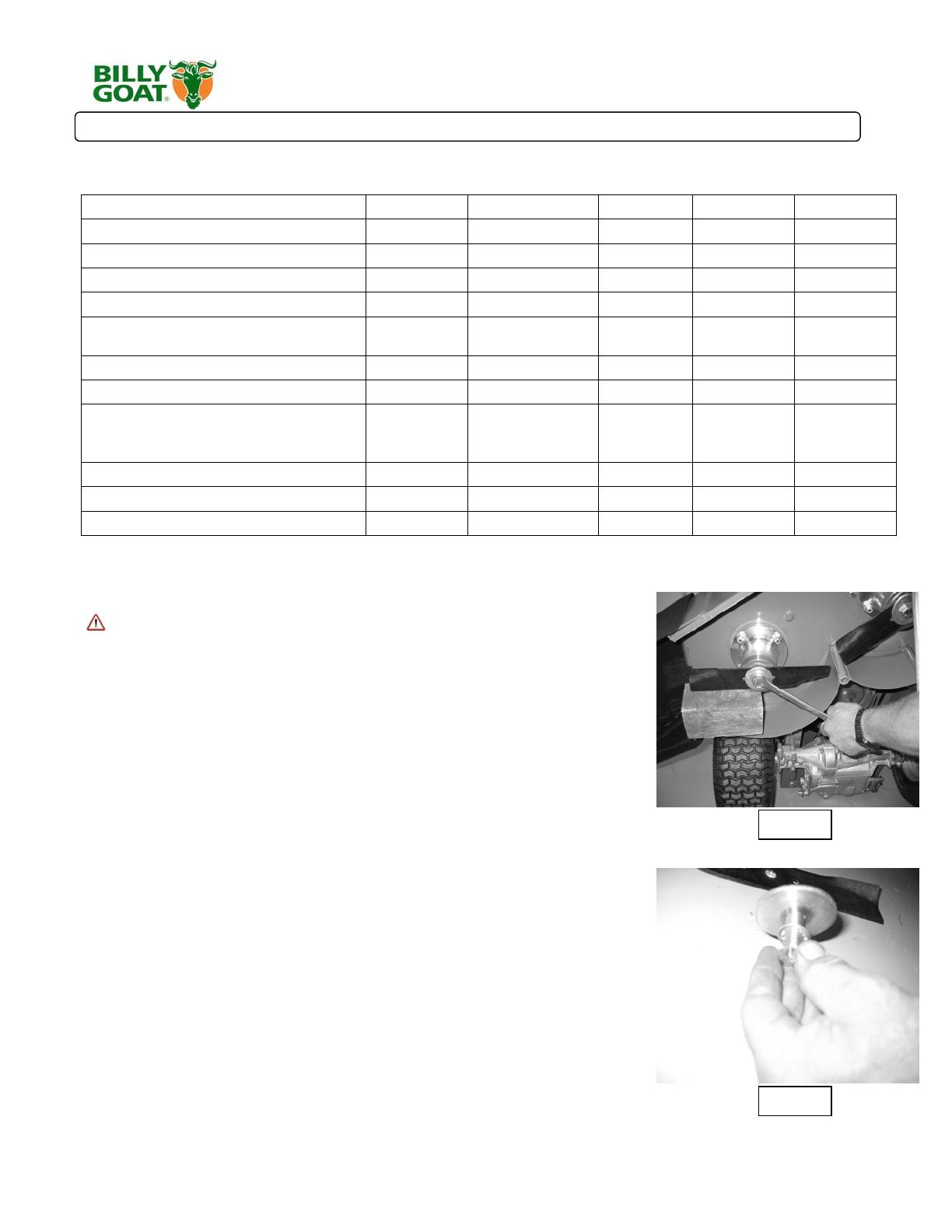
Problem Possible Cause Solution
Engine w ill not start. Choke not on. O ut of gasoline, bad or old gas.
Spark plug w ire disconnected. D irty air
cleaner. Blade clutch is engaged
M o v e th ro ttle to s ta rt p o s itio n . C h e c k
G asoline. C heck for spark w ith an
approved tester. Clean or replace air
cleaner. Disengage the Blade clutch
le v e r.
Engine w ill not stop Dam aged control cable. H arness W ire is
disconnected or dam aged. Dam aged ignition
switch.
Replace control cable. R econnect
harness wire or replace if dam aged.
Replace switch.
Engine runs poorly Spark plug w ire loose. Engine R PM set too
low. C arburetor out of adjustm ent. W ater or
dirt in fuel system . Spark plug fouled, faulty or
wrong gap
Sharpen or replace blade (pg 13). C heck
engine R PM (refer to engine m anual).
Adjust carburetor (refer to engine
m anual). Reset gap or replace spark
plug (refer to engine m anual).
Abnorm al vibration. · Loose or out of balance blade. Bent blade.
Loose engine bolts
Stop work im m ediately. C heck blade
m ount and balance. R eplace dam aged
or bent blade if required (pg 13). C heck
engine m ount.
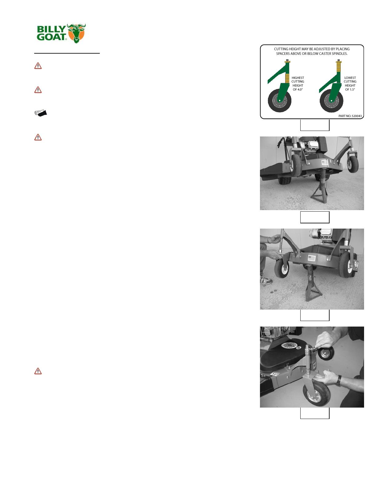
Uneven cut Height adjust is not set correctly. D ull or bent
blade. Tire pressure low on one side.
Be sure height adjust is set the sam e on
both sides(pg 11). Sharpen or replace
blade (pg 13). Adjust pressure.
W ill not cut or has poor
cutting perform ance
Dull or bent Blade. C logged deck. Engine
running at too low R PM . W et G rass.
Excessively high grass.
Sharpen or replace blade (pg 13).
U nclog deck(pg 11). Check engine RPM
(re fe r to e n g in e m a n u a l). D o n o t m o w
when grass is wet. M ow once at a high
cuting setting then m ow again at desired
s e ttin g o r m a k e a n a rro w e r c u ttin g p a th .
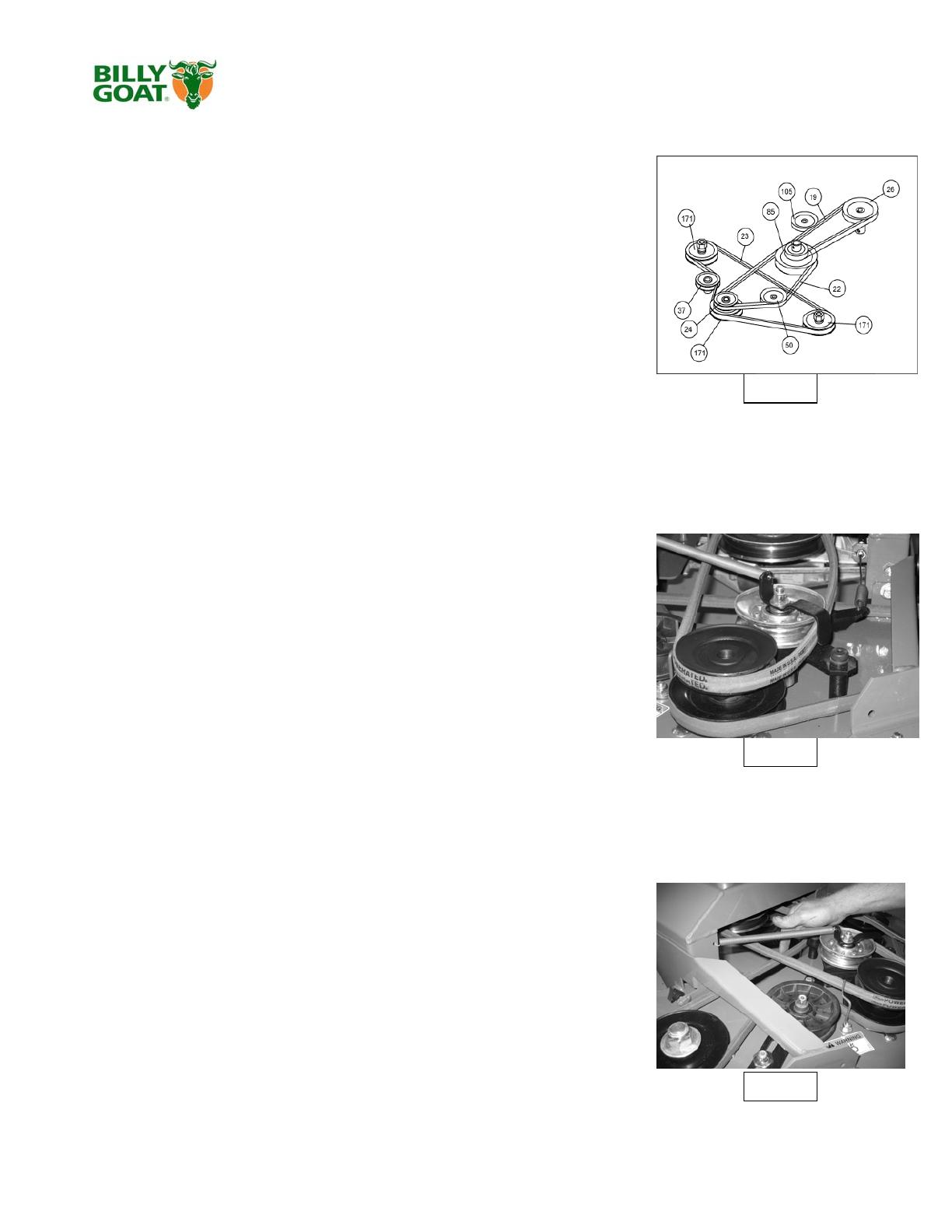
Belt slips or sm okes Belt tension too low . Belt worn or stretched.
Pulleys worn or dam aged. C ontrol cable out of
adjustm ent.
Increase tension at idler (pg 14). Replace
belt. Replace Pulleys. Adjust control
cable
No self propelling Not set to gear. O ut of adjustm ent clutch
cable. Broken clutch cable. W orn or broken
belt.
Shift lever to desired gear. Adjust clutch
cable(pg 15). R eplace with new cable.
Replace belt (pg 14).
Self propelled drive will
not release.
Clutch cable out of adjustm ent. Dam aged
drive clutch lever.
Adjust clutch cable (pg 15). R eplace
drive clutch lever.
E n g in e is lo c k e d , w ill n o t
pull over.
Debris locked against blade. D am aged engine.
Broken control cable.
Rem ove debris (pg 11). R efer to engine
owner's m anual. Replace control cable.
Not for Reproduction
Part No 520187 Form No F061207C
18
FM Owner’s Manual
PARTS DRAWING FM
130
175
21
87
179
155
81
178
155
41
174
145
53
139
20
62
126
38
42
1
38
126
127
189
7
171
33
35
103
18
151
71
144
126
180
151
144
144
151
144
56
119
127
5
147
2
16
17
65
171
5
46
23
173
171
172
167
168
165
164
163
24
168
169
170
166
173
172
Not for Reproduction
Part No 520187 Form No F061207C
19
FM Owner’s Manual
PARTS LIST
ITEM
FM3301E FM3301
NO.
Part NO. Part NO.
1 BUSHING BRONZE 520184 4 520184 4
2 LABEL DANGER FLY 810736 1 810736 1
5 LABEL WARNING 400424 2 400424 2
7 LABEL HGT. GUIDELINE 520043 1 520043 1
16 SPRING EXHAUST CHUTE 510205 1 510205 1
17 LABEL WARNING MOWER 510206 1 510206 1
18 BLADE 11.88” 520001 3 520001 3
20 LYNCH PIN 3/16” X 1 9/16 520004 2 520004 2
21 WHEEL AND TIRE 8” ASSY. 520005 2 520005 2
23 BELT SPINDLE DRIVE 520007 1 520007 1
24 SPINDLE ASSY FM 520008 3 520008 3
33 WASHER 1/2 INNER TOOTH 520025 3 520025 3
35 SCREW CAP 1/2-20X1.25 520028 3 520028 3
38 BUSHING CASTER SPACERS 520034 12 520034 12
41 SPACER FRONT CASTER 520041 2 520041 2
42 EXHAUST CHUTE DEFLECT. 520042 1 520042 1
46 PULLEY DECK FRONT DRIVE 520047 1 520047 1
53 CASTER ARM FM WA 520067-S 2 520067-S 2
56 DECK WA W/ LABELS 520071-S 1 520071-S 1
62 BRACKET CASTER FM WA 520077 2 520077 2
65 PLUG 3/8” BUTTON HEAD 520081 2 520081 2
71 WIRE BELT FINGER 520088 1 520088 1
81 GUARD BELT W/ LABELS FM 520100-S 1 520100-S 1
87 KNOB 3 PRONG 1/4” 520109 4 520109 4
103 WASHER 1/2” X 2 610308-P 3 610308-P 3
119 LABEL DANGER 900327 1 900327 1
126 BOLT CARRIAGE 3/8-16X1” ZP 8024058 5 8024058 5
127 BOLT CARRIAGE 3/8-X 1 1/4 8024059 16 8024059 16
130 SCREW CAP 1/4 - 20 X 7" 8041023 1 8041023 1
139 SCREW CAP 1/2-13 X 4 1/2 8041107 2 8041107 2
144 NUT 3/8-16 LOCK NYLON 8160003 21 8160003 21
145 NUT 1/2-13 LOCK NYLON 8160005 2 8160005 2
147 NUT 1/4-20 LOCK NYLON 8160001 1 8160001 1
151 WASHER 5/16” FC 8171003 20 8171003 20
155 WASHER 3/4 FC 8172015 4 8172015 4
163 HOUSING SPINDLE 520008-01 3 520008-01 3
164 SHAFT SPINDLE 1215 C. D. S. 520008-02 3 520008-02 3
165 BEARING BALL 6305-25 520008-03 6 520008-03 6
166 WASHER 520008-04 3 520008-04 3
167 SHIELD 520008-05 3 520008-05 3
168 RETAINING RING 520008-06 6 520008-06 6
169 RETAINING RING 520008-07 3 520008-07 3
170 WOODRUFF KEY # 605 520008-08 3 520008-08 3
171 PULLEY 4.75” DIA. 3/4” BORE 520008-09 3 520008-09 3
172 MACHINERY BUSHING 3/4” 520008-10 3 520008-10 3
173 NUT 3/4-16 NYLON HEX 520008-11 3 520008-11 3
174 FRONT CASTER ASSY. 520140 1 520140 1
175 BEARING CASTER WHEEL 520124 4 520124 4
178 LABEL BGI BIG CIRCLE 430303 1 430303 1
179 LABEL 33" CUT FM 520115 1 520115 1
180 LABEL MADE IN USA 520116 1 520116 1
189 FITTING GREASE 610363 2 610363 2
DESCRIPTION QTYQTY
Not for Reproduction
Part No 520187 Form No F061207C
20
FM Owner’s Manual
PARTS DRAWING FM
II
I
IV
III
I
II
IV
III
148
59
137
147
9
143
144
137
151
187
138
151
29
86
55
151
37
137
151
184
184
104
140
144
36
58
83
36
151
44
50
13
91
89
123
183
not included
Battery is
96
109
106
111
120
49
159
85
92
150
143
144
144
83
125
118
90
181
93
102
6
6
102
51
116
4
40
190
178
182
151
143
Not for Reproduction
  • Page 1 1
  • Page 2 2
  • Page 3 3
  • Page 4 4
  • Page 5 5
  • Page 6 6
  • Page 7 7
  • Page 8 8
  • Page 9 9
  • Page 10 10
  • Page 11 11
  • Page 12 12
  • Page 13 13
  • Page 14 14
  • Page 15 15
  • Page 16 16
  • Page 17 17
  • Page 18 18
  • Page 19 19
  • Page 20 20
  • Page 21 21
  • Page 22 22
  • Page 23 23
  • Page 24 24
  • Page 25 25
  • Page 26 26
  • Page 27 27
  • Page 28 28

Simplicity MOWER, BILLY GOAT Owner's manual

Category
Garden tools
Type
Owner's manual
This manual is also suitable for

Ask a question and I''ll find the answer in the document

Finding information in a document is now easier with AI