Page is loading ...

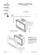
A r b o r
Wood Stove
Owner's Manual
• Freestanding Stove
• Mobile-Home Approved
• Alcove Approved
• Hearth-Stove Approved
Save these instructions
for future reference
SAFETY NOTICE:
If this appliance is not properly installed, a house fire may
result. For your safety, follow the installation directions.
Contact local building or fire officials about restrictions and
installation inspection requirements in your area.
4800 Harbour Pointe Blvd. SW
Mukilteo, WA 98275
Copyright 2007, T.I.
$10.00 100-01190_000
4070326
Listed
Tested to: U.L. 1482
Test Report # 028-S-75-2

2 Introduction
© Travis Industries 100-01190_000 4070326
Introduction
We welcome you as a new owner of an Arbor wood-burning stove. In purchasing an Arbor you have
joined the growing ranks of concerned individuals whose selection of an energy system reflects both a
concern for the environment and aesthetics. The Arbor is one of the finest appliances the world over.
This manual will explain the installation, operation, and maintenance of this appliance. Please familiarize
yourself with the Owner's Manual before operating your appliance and save the manual for future
reference. Included are helpful hints and suggestions which will make the installation and operation of
your new appliance an easier and more enjoyable experience. We offer our continual support and
guidance to help you achieve the maximum benefit and enjoyment from your appliance.
Important Information
No other Avalon Arbor appliance has the same serial
number as yours. The serial number is stamped onto
the label on the back of the appliance.
This serial number will be needed in case you require
service of any type.
Model: Avalon Arbor
Serial Number:
Purchase Date:
Purchased From:
Register your warranty online at:
traviswarranty.com
Or, mail your warranty card to:
Travis Industries House of Fire
4800 Harbour Pointe Blvd. SW
Mukilteo, WA 98275
Save Your Bill of Sale.
To receive full warranty coverage, you will
need to show evidence of the date you
purchased your heater. Do not mail your Bill
of Sale to us.
We suggest that you attach your Bill of Sale
to this page so that you will have all the
information you need in one place should the
need for service or information occur.

Table of Contents 3
© Travis Industries 100-01190_000 4070326
General Information
Introduction & Important Information...................... 2
Safety Precautions ............................................ 4
Features & Specifications.................................... 6
Stove Installation
Planning the Installation...................................... 7
Preparation for Installation..............................7
Stove Installation Considerations .....................7
Floor Protection Requirements ............................. 8
Stove Placement Requirements ........................... 8
Clearances ...................................................... 8
Top View - Straight Installation ........................9
Top View - Corner Installation ......................... 9
Bypass Handle Installation .................................. 10
Rear Vent Configuration ..................................... 10
Chimney Connector Requirments ......................... 11
Chimney Requirements ...................................... 12
Chimney Termination Requirements...................... 13
Outside Air Requirements ................................... 13
Alcove Installation Requirements .......................... 14
Mobile Home Requirements ................................ 15
INSTALLATION DIAGRAMS
Standard Ceiling with a Factory Built Chimney....16
Cathedral Ceiling with a Factory Built Chimney... 16
Hearth Stove Positive Connection....................17
Hearth Stove Direct Connection.......................17
Interior or Exterior Masonry Chimney................18
Operating Your Appliance
Safety Notice.................................................... 19
Operating the Stove when it is Hot ...................19
Before Your First Fire ......................................... 19
Curing the Paint ........................................... 19
Over-Firing the Stove .................................... 19
Opening the Doors ............................................ 20
Bypass Operation.............................................. 21
Loading Lid Operation ........................................ 21
Starting a Fire................................................... 22
Adjusting the Burn Rate ...................................... 23
Approximate Air Control Settings ..................... 23
Operating Your Appliance (continued)
Ash Removal.................................................... 24
Ashpan Removal..........................................24
Blower Operation .............................................. 25
Re-Loading the Stove......................................... 25
Overnight Burn ................................................. 25
Normal Operating Sounds ................................... 25
Hints for Burning ............................................... 26
Selecting Wood................................................. 26
Why Dry Wood is Key....................................26
Wood Cutting and Storage.............................. 26
Troubleshooting ................................................ 27
Maintaining Your Appliance
Daily Maintenance (while stove is in use) ............... 28
Remove Ash (if necessary).............................28
Clean the Glass (if necessary).........................28
Monthly Maintenance (while appliance is in use) ...... 29
Door and Glass Inspection.............................. 29
Creosote - Formation and Need for Removal......29
Yearly Maintenance ........................................... 30
Touch Up Paint ............................................30
Cleaning the Air Duct and Blower (if applicable).. 30
Door Parts ....................................................... 31
Replacing the Glass......................................31
Replacing the Door Gasket.............................31
Replacing the Loading Lid Gasket....................31
Replacing the Door Handle.............................31
Firebox Parts.................................................... 32
Brick Removal & Replacement ........................32
Combustor Removal & Replacement ................32
Warranty
Warranty ......................................................... 34
Listing Information
Listing Information ............................................. 35
Optional Equipment
Rear Blower Installation ...................................... 36
Index
Index .............................................................. 38

4 Safety Precautions
© Travis Industries 100-01190_000 4070326
The viewing door must be
closed and latched during
operation.
Never block free airflow through
the air vents on this appliance.
Gas
Gasoline or other flammable
liquids must never be used to
start the fire or "Freshen Up" the
fire. Do not store or use
gasoline or other flammable
liquids in the vicinity of this
appliance.
This appliance is designed and
approved for the burning of cord
wood only. Do not attempt to
burn any other type of fuel other
than cord wood in this
appliance, it will void all
warranties and safety listings.
ASHES
Ashes must be disposed in a
metal container with a tight lid
and placed on a non-
combustible surface well away
from the home or structure.
Do not touch the appliance while
it is hot and educate all children
of the danger of a high-
temperature appliance. Young
children should be supervised
when they are in the same room
as the appliance.
36"
Keep furniture, drapes, curtains,
wood, paper, and other
combustibles a minimum of 36"
away from the front of the
appliance.
This appliance must be properly
installed to prevent the
possibility of a house fire. The
instructions must be strictly
adhered to. Do not use
makeshift methods or
compromise in the installation.
Ok
Contact your local building
officials to obtain a permit and
information on any installation
restrictions or inspection
requirements in your area.
Notify your insurance company
of this appliance as well.
Inspect the chimney connector
and chimney at least twice
monthly and clean if necessary.
Creosote may build up and
cause a house fire.
Do not connect this appliance to
any chimney serving another
appliance.
Type
HT
Clay
Liner
This appliance must be
connected to a listed high
temperature (UL 103 HT)
residential type chimney or an
approved masonry chimney with
a standard clay tile, or stainless
steel liner.

Safety Precautions 5
© Travis Industries 100-01190_000 4070326
Mobile
Home
When installed in a mobile
home, this appliance must be
bolted to the floor, have outside
air, and not be installed in the
bedroom (Per H.U.D.
requirements). Check with local
building officials.
Do not place clothing or other
flammable items on or near this
appliance.
Never try to repair or replace
any part of this appliance unless
instructions are given in this
manual. All other work must be
done by a trained technician.
Do not make any changes or
modifications to an existing
masonry fireplace or chimney to
install this appliance.
Do not make any changes to the
appliance to increase
combustion air.
Allow the appliance to cool
before carrying out any
maintenance or cleaning.
Overfiring the appliance may
cause a house fire. If a unit or
chimney connector glows, you
are overfiring.
Maintain the door and glass seal
and keep them in good
condition.
Avoid placing wood against the
glass when loading. Do not
slam the door or strike the glass.
Do not use a grate or other
device to elevate the fire off of
the firebox floor. Burn the fire
directly on the bricks.
This
Manual
Do not throw this manual away.
This manual has important
operating and maintenance
instructions that you will need at
a later time. Always follow the
instructions in this manual.
Travis Industries, Inc. grants
no warranty, implied or
stated, for the installation or
maintenance of your
appliance, and assumes no
responsibility of any
consequential damage(s).

6 Features & Specifications
© Travis Industries 100-01190_000 4070326
Installation Options
• Freestanding
• Freestanding in an Alcove
• Freestanding in a Mobile Home
• Freestanding Hearth Stove
Features
• EPA Phase II Approved
• 2.3 Cubic Foot Firebox Volume
• Single Operating Control
• Accepts Logs Up to 21” Long
• Cast Iron Construction
• Heavy Duty Refractory Firebrick
• Optional High-Tech Blower
Heating Specifications
Approximate Maximum Heating Capacity (in square feet)* Up to 2,000
Maximum BTU's per Hour (Cord Wood Calculation) 73,100
Overall Efficiency (Oregon Method) 70 %
Maximum Burn Time Up to 12 Hours
* Heating capacity will vary depending on the home's floor plan, degree of insulation, and the outside
temperature. It is also affected by the quality and moisture level of the fuel.
Dimensions
Weight: 375 Lbs.
NOTE:
Measure side, corner, and back
clearances from the stove top.
2-5/8"
17"
28-3/4"
27-1/4"
6-3/4"
25-1/4"
22-7/8"
Figure 1
Emissions
2.4 Grams Per Hour (EPA Phase II Approved) – Tests conducted by OMNI-Test Laboratories.

Stove Installation (for qualified installers only) 7
© Travis Industries 100-01190_000 4070326
SAFETY NOTICE:
Please read this entire manual before you install and use your new room heater. Failure
to follow instructions may result in property damage, bodily injury, or even death.
Contact local building or fire officials about restrictions and installation inspection
requirements in your area.
Always use gloves when operating a hot stove. The door handles, loading lid, bypass handle, and other
components become very hot during normal use.
Planning The Installation
We suggest that you have an authorized Travis Industries dealer install your stove. If you install the
stove yourself, your authorized dealer should review your installation plans.
Check with local building officials for any permits required for installation of this stove and notify your
insurance company before proceeding with installation.
Preparation for Installation
• Check for damage to the exterior of the stove.
• Check the interior of the firebox (replace cracked firebrick and make sure baffle is in place).
The stove can be lightened for transportation by removing the doors, loading lid, and firebricks. Replace
these components before operation.
• Install the bypass handle (included in the owner’s pack - see page 10).
Stove Installation Considerations
The table below details the six most common types of installations and the considerations for each type.
Alternative methods of installation are available if they comply with local building codes.
Installation Type Considerations
Standard Ceiling with a Factory Built Chimney
(Page 16)
• Requires ceiling and roof penetration
• Provides best draft
Cathedral Ceiling with a Factory Built Chimney
(Page 16)
• Cathedral style chimney support required
• Provides best draft
Hearth Stove Positive Connection
(Page 17)
• Utilizes existing masonry fireplace (not approved for zero
clearance (metal) fireplaces)
• Provides good draft due to full reline
• Easier to clean than direct or horizontal hearth stove
Hearth Stove Direct Connection
(Page 17)
• Utilizes existing masonry fireplace (not approved for zero
clearance (metal) fireplaces)
• Requires construction of a "block-off plate"
• Draft reduced due to elbows & chimney cross section
Interior Masonry Chimney
(Page 18)
• Utilizes existing masonry chimney (not approved for zero
clearance (metal) fireplaces)

8 Stove Installation (for qualified installers only)
© Travis Industries 100-01190_000 4070326
Floor Protection Requirements
• Floor protection must extend 6" to the sides and rear of the stove and 16" to the front of the stove
39.25” wide by 44.875" deep - see Figure 2 and Figure 3).
• Floor protection must be non-combustible and at least .018" thick (26 guage).
Stove Placement Requirements
Clearances may be reduced by methods specified in NFPA 211, listed wall shields, pipe shields, or
other means approved by local building or fire officials.
• Stove must be placed so that no combustibles are within, or can swing within (e.g. drapes, doors), 36"
of the front of the stove
• Must maintain the clearances to combustibles listed below (drywall, furniture, etc.):
Clearances
• The following clearances must be met (see Figure 2 and Figure 3)
Minimum Clearance Singlewall
Connector
Singlewall
Connector with
Pipe Shield**
Reduced
Clearance*
A Sidewall to stove 18.00” 18.00” 18.00”
B Backwall to stove 27.25” 17.25” 20.75”
C Cornerwall to stove 19.00” 14.00” 14.00”
D Connector to sidewall 28.75” 28.75” 28.25”
E Connector to backwall 21.00” 11.00” 14.00”
F Connector to cornerwall 23.00” 18.00” 17.50”
*Reduced clearance installations require one of the chimneys and connectors listed below:
AMERI-TEC model DCC connector with AMERI-TEC UL 103 HT chimney
DURAVENT model DVL connector with DURAVENT UL 103 HT chimney
GSW Super Chimney Twenty-One connected directly to appliance
I.C.C. Excel HP connector with I.C.C. UL 103 HT chimney
METALFAB model DW connector with METALFAB UL 103 HT chimney
OLIVER MACLEOD PROVENT model PV connector with OLIVER MACLEOD UL 103 HT chimney
SECURITY model DP connector with SECURITY UL 103 HT chimney
SELKIRK model DSP connector with SELKIRK UL 103 HT chimney
Standard Masonry Chimney with any one of the above listed connectors
NOTE: Reduced clearance connectors may not connect to the flue collar – an appliance adapter
may be required.
NOTE: Mobile Home installations must use the reduced clearance connector and clearances
listed above.
NOTE: Standard residential installations with reduced clearance connector may use the
“Connector to Wall” clearance determined by the connector manufacturer if approved by
local code. This clearance is established by the connector manufacturer and falls under
the connector manufacturer’s listing. “Stove to Wall” clearances must always be met.
** The pipe shield must meet NFPA 211 guidelines (such as the HomeSaver® Stovepipe shield) and
must extend from the flue collar to a location 16” below the ceiling.

Stove Installation (for qualified installers only) 9
© Travis Industries 100-01190_000 4070326
Top View -
Straight Installation
Measure rear and side clearances from
the nearest edge of the stove top.
Floor Protection
27-1/4”
22-7/8”
16” Min.
Measure front clearances from the
face of the stove (door opening).
6” Min.
6” Min.
Clearance A
NOTE: vent diameter
may vary depending on
brand and model.
Clearance E
Clearance B
Back Wall
Side Wall
2-5/8”
Clearance D
Typical Flue Center
Singlewall 24"
Reduced Clearance 17.5"
Singlewall w Pipe Shield 14"
Minimum Flue Center 31-3/4"
3-1/4”
Figure 2
Top View -
Corner Installation
Floor Protection
16” Min.
6” Min.
6” Min.
Measure rear and side clearances from
the nearest edge of the stove top.
Measure front clearances from the
face of the stove (door opening).
NOTE: vent diameter
may vary depending on
brand and model.
Corner Wall
Corner Wall
Clearance C
Clearance F
Typical Flue Center
Singlewall 26"
Reduced Clearance 21"
Singlewall w Pipe Shield 21"
27-1/4”
22-7/8”
2-5/8”
3-1/4”
Figure 3

10 Stove Installation (for qualified installers only)
© Travis Industries 100-01190_000 4070326
Bypass Handle Installation
See Figure 4 for details on installing the bypass handle.
Line up the set screws on the bypass handle
with the dimples on the bypass shaft. Tighten
with the included 1/8” hex wrench.
1/8" Hex
Figure 4
Rear Vent Configuration
The rear vent configuration is only for masonry fireplace installations (hearth stove). All steel chimney
applications require the top vent configuration.
The vent (chimney connector) may be directed to the rear of the appliance when installed into a masonry
fireplace. See Figure 5 for details.
The flue collar is held in place with three bolts
and two nuts. Use two 7/16" open-end
wrenches to remove the bolts and nuts.
7/16" Wrench
NOTE: Make sure the gasket
underneath the flue collar is properly
located and seals the flue collar when
it is installed.
Open the bypass - this
allows for access to the
nut under the flue collar.
Remove the flue collar and rotate it to the rear.
Use the existing bolts and nuts to attach the
sides of the flue. For the center connection
use the bolt and acorn nut included in the
owner's pack.
Figure 5

Stove Installation (for qualified installers only) 11
© Travis Industries 100-01190_000 4070326
Chimney Connector Requirements
• Chimney connector is required from the flue collar of the stove to the factory-built chimney (see
Figure 7) or masonry chimney (see Figures 13, 14, and 15).
• The chimney connector must be 6” diameter and a minimum 24 gauge black steel, 26 gauge blued
steel, or one of the reduced-clearance connectors listed on page 8.
NOTE: Aluminum or galvanized steel is not allowed – these materials can not withstand the flue
temperatures and may give off toxic fumes when heated.
NOTE: Standard residential installations may use single-wall connector (Mobile-Homes may not).
• The chimney connector may not pass through a ceiling, attic, roof, closet, or any other concealed
space (use listed UL 103 HT chimney – see “Chimney Requirements for details). DO NOT USE
CONNECTOR PIPE AS CHIMNEY.
• The chimney connector should be as short and direct as possible. No more than 180
o
of elbows (two
90
o
elbows, or two 45
o
& one 90
o
elbow, etc.) may be used for the entire system (connector and
chimney).. Horizontal runs should slope upwards 1/4” per foot and be a maximum 36” long.
• The chimney connector must be installed with the crimped end pointing downwards (see Figure 7).
This prevents creosote from leaking to the exterior of the pipe.
• The chimney connector must be fastened to the stove and each adjoining section (and chimney).
• In cases where the chimney connector must be passed through a combustible wall or partition, the
following NFPA 211 method may be used if local building codes permit. Check with local authorities
before installation to insure all necessary requirements have been met. Figure 6 details a wall pass-
through based on the NFPA 211 standard.
NFPA 211 Wall Pass-Through
(see NFPA 211 for a full description)
12” Min.
12” Min.
Combustible Materials
Brick
Fire Clay Thimble
Figure 6

12 Stove Installation (for qualified installers only)
© Travis Industries 100-01190_000 4070326
Chimney Requirements
• DO NOT CONNECT THIS UNIT TO A CHIMNEY FLUE SERVING ANOTHER APPLIANCE.
• UL 103 HT Chimney must be used from the first ceiling or floor penetration to the chimney cap.
• Use 6" diameter type UL 103 HT chimney from one manufacturer (do not mix brands) or code
approved masonry chimney with a flue liner.
• Chimney must be fastened to each adjoining section.
• Follow the chimney manufacturer's clearances and requirements.
• Use the chimney manufacturer's fire stops, attic guards, roof supports, and flashings when passing
through a ceiling
• No more than 180
o
of elbows (two 90
o
elbows, or two 45
o
& one 90
o
elbow, etc.) may be used for the
entire system (connector and chimney).
NOTE: Additional elbows may be allowed if draft is sufficient. Whenever elbows are used the draft is
adversely affected. Additional chimney height may be required to boost draft.
Chimney Cap
(See the section "Chimney
Termination Requirements"
for more details)
Factory Built
Chimney Sections
Minimum Air Space to
Combustibles (See
Chimney Manufacturer's
Instructions - usually 2")
Floor Penetration Equipment
(Attic Radiation Shield with
Chimney Support)
Roof Penetration Equipment
(Roof Radiation Shield,
Flashing, Storm Collar)
}
}
Floor
Protection
Connector Clearance
(as outlined in this manual)
}
Minimum System 15'
Maximum System 33'
Connector
On singlewall pipe
the crimped end
points downward.
Figure 7
Drafting
Performance
This appliance relies upon natural draft to operate. External forces, such as wind,
barometric pressure, topography, or factors of the home (negative pressure from exhaust
fans, chimneys, air infiltration, etc.), may adversely affect draft. Travis Industries can not be
responsible for external forces leading to less than optimal performance.

Stove Installation (for qualified installers only) 13
© Travis Industries 100-01190_000 4070326
Chimney Termination Requirements
• Must have an approved cap (to prevent water from entering)
• Must not be located where it will become plugged by snow or other material
• Must terminate at least 3' above the roof and at least 2' above any portion of the roof within 10' (see
Figure 8)
Slanted Roofs
F
lat Roofs
Chimney must
extend 3'
above the roof
Chimney must extend 2'
above any portion of the roof
within 10' of the chimney
Chimney must
extend 3'
above the roof
Chimney must extend 2'
above any portion of the roof
within 10' of the chimney
Figure 8
Outside Air Requirements
• Required for mobile homes and in certain localities (check with building officials)
• Must not be drawn from an enclosed space (garage, unventilated crawl space)
• Requires 3” aluminum duct (do not use plastic “dryer-vent”) and a hose-clamp for securing to the
stove. Maximum 4’ length. NOTE: A 10’ length is allowed if using 4” diameter duct (use a 3” to 4”
converter).
• If using the optional blower, you may need to “ovalize” the duct to route it under the blower box.
3” Air Duct (max. 4’ length)
A screen is required to prevent
rodents from entering.
Outside air entrance must be placed so it
does not become blocked by snow.
Air may be drawn from a ventilated crawl space.
Botttom of Stove
Use a hose clamp to secure the
aluminum air duct to the air inlet
flange on the stove.
Air Duct (3” Dia.)
Figure 9

14 Stove Installation (for qualified installers only)
© Travis Industries 100-01190_000 4070326
Alcove Installation Requirements
Whenever the stove is placed in a location where the ceiling height is less than 8' tall, it is considered an
alcove installation. Because of the reduced height, the special installation requirements listed below must
be met.
• Chimney connector and chimney must be one of the following types:
AMERI-TEC model DCC connector with AMERI-TEC UL 103 HT chimney
DURAVENT model DVL connector with DURAVENT UL 103 HT chimney
GSW Super Chimney Twenty-One connected directly to appliance
I.C.C. Excel HP connector with I.C.C. UL 103 HT chimney
METALFAB model DW connector with METALFAB UL 103 HT chimney
OLIVER MACLEOD PROVENT model PV connector with OLIVER MACLEOD UL 103 HT chimney
SECURITY model DP connector with SECURITY UL 103 HT chimney
SELKIRK model DSP connector with SELKIRK UL 103 HT chimney
Standard Masonry Chimney with any one of the above listed connectors
NOTE: Reduced clearance connectors may not connect to the flue collar – an appliance adapter may be required.
• The clearances below must be met:
Minimum Clearance
(See Figure 10 below)
Combustible
Alcove
A Sidewall to stove 18.00"
B Backwall to stove 20.75"
D Connector to sidewall 28.25"
E Connector to backwall 14.00"
G Maximum depth of alcove 48.00"
H Minimum width of alcove 63.25"
J Minimum height of alcove 84.00"
a
d
e
h
j
g
b
Figure 10

Stove Installation (for qualified installers only) 15
© Travis Industries 100-01190_000 4070326
Mobile Home Requirements
• Outside air must be installed - see "Outside Air Requirements" on page 13
• Chimney connector and chimney must be one of the following types:
AMERI-TEC model DCC connector with AMERI-TEC UL 103 HT chimney
DURAVENT model DVL connector with DURAVENT UL 103 HT chimney
GSW Super Chimney Twenty-One connected directly to appliance
I.C.C. Excel HP connector with I.C.C. UL 103 HT chimney
METALFAB model DW connector with METALFAB UL 103 HT chimney
OLIVER MACLEOD PROVENT model PV connector with OLIVER MACLEOD UL 103 HT chimney
SECURITY model DP connector with SECURITY UL 103 HT chimney
SELKIRK model DSP connector with SELKIRK UL 103 HT chimney
Standard Masonry Chimney with any one of the above listed connectors
NOTE: Reduced clearance connectors may not connect to the flue collar – an appliance adapter may be required.
• Stove placement must maintain the following clearances to combustibles (drywall, furniture, etc.)
A
B
F
C
Measure clearances from the
nearest edge of the stove top.
D
E
C
Figure 11
Minimum Clearance
(See the illustration above)
Reduced Clearance
Connector
A Sidewall to stove 18.00”
B Backwall to stove 20.75”
C Cornerwall to stove 14.00”
D Connector to sidewall 28.25”
E Connector to backwall 14.00”
F Connector to cornerwall 17.50”
• If using offsets, use the connector clearance listed in Figure 12,
not the connector manufacturer's clearance.
• The appliance must be secured to the floor (consult your
building official). Secure the outside air boot to the floor and
stove to insure the stove does not dislocate.
• Mobile home installations require a spark arrester at the
chimney termination.
• The appliance must be grounded to the chassis of the mobile
home (consult your building official).
• WARNING:DO NOT INSTALL IN SLEEPING ROOM.
• CAUTION:THE STRUCTURAL INTEGRITY OF THE MOBILE
HOME FLOOR, WALL, AND CEILING/ROOF MUST BE
MAINTAINED.
12” Min.
Connector Clearance
(as outlined above)
Stove Clearance
(as outlined above)
Figure 12

16 Stove Installation (for qualified installers only)
© Travis Industries 100-01190_000 4070326
Standard Ceiling
with a Factory
Built Chimney
Chimney Cap
(See the section "Chimney
Termination Requirements"
for more details)
Chimney Sections
Minimum Air Space to
Combustibles (See
Chimney Manufacturer's
Instructions - usually 2")
Chimney Connector Sections
Follow the chimney
manufacturer's instructions
and clearances for roof
penetrations. A storm collar
and flashing are required
(some require a radiation
shield).
}
}
Minimum 15'
Maximum 33'
Stove Clearances
(See the section "Stove
Placement Requirements"
for more details)
Floor Protection
(See the section "Floor
Protection Requirements"
for more details)
Follow the chimney
manufacturer's instructions
and clearances for floor
penetrations. A ceiling
support is required, an attic
insulation shield is required
where insulation is present.
Insulation
Figure 13
Cathedral Ceiling
with a Factory
Built Chimney
Chimney Cap
(See the section "Chimney
Termination Requirements"
for more details)
Chimney Sections
Minimum Air Space to
Combustibles (See Chimney
Manufacturer's Instructions -
usually 2")
Follow the chimney
manufacturer's instructions
and clearances for roof
penetrations. A storm
collar, flashing, and
cathedral-style chimney
support are required
(some require a radiation
shield).
}
Minimum 15'
Maximum 33'
Stove Clearances
(See the section "Stove
Placement Requirements"
for more details)
Floor Protection
(See the section "Floor
Protection Requirements"
for more details)
Chimney
Connector
Sections
Figure 14

Stove Installation (for qualified installers only) 17
© Travis Industries 100-01190_000 4070326
Hearth Stove
Positive
Connection
NOTE:
Most factory-built
chimney manufacturers
make stainless steel
chimney liners, either
flexible or rigid. This
provides a wide variety
of installation options.
Make sure to follow the
manufacturer's
instructions for
installation and support.
Remove damper
or wire it open
Airtight Insulated
Clean-Out
Min. 36"
Combustible
Mantle
NOTE: The entire fireplace and
chimney must be clean, undamaged,
and meet all local building codes
(UBC, etc.). Damage must be
repaired prior to installation. The
chimney must be 15' to 33' tall.
Floor Protection
(See the section
"Floor Protection
Requirements"
for more details)
See the section
"Stove Placement
Requirements" for
minimum clearances
required.
The liner must be
stainless steel connector
or flexible vent. Follow
the liner manufacturer's
instructions for installation
and support.
Cap and flashing
prevents water from
entering
Figure 15
Hearth Stove Direct
Connection
NOTE:
Direct connections require
installation of an airtight,
non-combustible block-off
plate or damper adapter.
Block-off plate or
damper adapter
Remove damper
or wire it open
Airtight
Insulated
Clean-Out
Stainless steel
chimney connector
must Extend 1' past
the block-off plate or
to the flue liner
NOTE: The chimney must have a clay
tile liner. If it does not, the installation
must use a positive connection (full
reline). The entire fireplace and
chimney must be clean, undamaged,
and meet all local building codes (UBC,
etc.). Damage must be repaired prior
to installation. The chimney must be
15' to 33' tall.
Clay
Liner
Floor Protection
(See the section "Floor
Protection Requirements"
for more details)
Combustible Mantle
Min. 36"
See the section
"Stove Placement
Requirements" for
minimum clearances
required.
Figure 16

18 Stove Installation (for qualified installers only)
© Travis Industries 100-01190_000 4070326
Interior or Exterior
Masonry Chimney
NOTE:
This type of installation
requires a UBC approved
masonry connector or
other method approved by
the NFPA 211 standard.
See Chimney Connector
Requirements on page 11
for further details.
Make sure the
clean-out seals in
place.
Clay Liner
See the section "Stove
Placement Requirements" for
minimum clearances required.
Min. 18"
clearance
to ceiling
This type of
installation requires
a UBC approved
masonry connector
or other method
approved by the
NFPA 211 standard.
Chimney connector sections
NOTE: The chimney must have a
clay tile liner. If it does not, the
installation must use a positive
connection (full reline). The
entire fireplace and chimney must
be clean, undamaged, and meet
all local building codes (UBC,
etc.). Damage must be repaired
prior to installation. The chimney
must be 15' to 33' tall.
See the section
"Floor Protection
Requirements"
Full Re-Line
(recommended)
Figure 17

Operating Your Appliance 19
© Travis Industries 100-01190_000 4070326
Safety Notice
If this appliance is not properly installed, a house fire may result. For your safety, follow the installation
directions. Contact local building or fire officials about restrictions and installation inspection
requirements in your area.
Read and follow all of the warnings on pages 4 and 5 of this manual.
Operating the Stove when it is Hot
Always use gloves when operating a hot stove. The door handles, loading lid, bypass handle, and other
components become very hot during normal use.
Before Your First Fire
Verify the Installation
Before starting the stove, verify that the stove is properly installed and all of the requirements in this
manual have been followed.
Keep all flammable materials 36" away from the front of the stove (drapes, furniture, clothing, etc.).
Curing the Paint
This heater uses a heat-activated paint that will emit some fumes while starting
the first fire. Open doors and windows to the room to vent these fumes. This
typically lasts two to four hours. You may also notice oil burning off of the interior
of the heater. This rust-stopping agent will soon dissipate. Furthermore, we
recommend you do not burn the stove at a high temperature during the first fire.
This allows the cast iron and finish to properly cure.
Door Gasket - The door gasket might adhere to the paint on the front of the
heater. Leave the door slightly ajar for the first fire and be careful when opening
the door after the first fire.
2 to 4 hours
Over-Firing the Stove
This stove was designed to operate at a high temperature. But due to differences in vent configuration,
fuel, and draft, this appliance can be operated at an excessive temperature. If the stove top or other area
starts to glow red, you are over-firing the stove. Shut the air control down to low and allow the stove to
cool before proceeding.
Over-firing may lead to damage of plated surfaces. If you are uncertain of over-firing conditions, we
suggest placing a stove thermometer (e.g. Rutland® Model 710) directly over the door on the stove top -
temperatures exceeding 800° are generally considered over-firing and will void the warranty.

20 Operating Your Appliance
© Travis Industries 100-01190_000 4070326
Opening the Doors
Typically the doors are only opened to start the fire. Use the Loading Lid to re-load the stove.
Swing the
doors open.
WARNING: Do not swing the doors past 90°. This may cause
the doors to strike the body of the stove and cause damage.
NOTE: When closing the doors, close the left door first. Then
shut the right door and tighten the latch.
A door latch tool is included for
operation when the door latch is
hot. Hang the tool on the air
control when not in use.
Open the bypass first (this prevents
smoke from entering the room).
Open the latch
The door becomes hot during use. Use a glove to open the door if the handle is hot.
To prevent smoke from entering the room, open the bypass before opening the door (see following page
for directions). You can also open the door a small amount and let air enter the firebox.
/