Miele Freezer F1471Vi User manual

Category
Fridge-freezers
Type
User manual

This manual is also suitable for

Miele Freezer F1471Vi: Experience the pinnacle of food preservation with our cutting-edge freezer, designed to keep your frozen goods fresh and delicious. Equipped with innovative features, it offers exceptional convenience and peace of mind.

Miele Freezer F1471Vi: Experience the pinnacle of food preservation with our cutting-edge freezer, designed to keep your frozen goods fresh and delicious. Equipped with innovative features, it offers exceptional convenience and peace of mind.

Operating and Installation
instructions
Freezer
with Ice/Water Dispenser
F 1471 Vi
To prevent accidents
and machine damage
read these instructions
before
installation or use.
M.-Nr. 07 155 770
en - US, CA
Installation instructions
To prevent accidents
and machine damage
read these instructions
before
installation or use.
Disposal of packing materials
The cardboard box and packing
materials are biodegradable and
recyclable. Please recycle.
Ensure that any plastic wrappings,
bags, etc., are disposed of safely and
kept out of the reach of babies and
young children. Danger of suffocation!
Disposal of an old appliance
Old appliances contain materials that
can be recycled. Please contact your
local recycling center about the
possibility of recycling these materials.
Before discarding an old appliance,
disconnect it from the gas and
electrical supply and cut off the power
cord to prevent it from becoming a
hazard.
Caring for the environment
50
Have the appliance installed by a
qualified technician, according to
the enclosed installation instructions.
The manufacturer is not liable for
damage to property due to an
incorrect installation or water
connection.
WARNING
This appliance is top-heavy and
must be secured to prevent it from
tipping forward.
Keep the door closed until the
appliance is completely installed
and secured as per the installation
instructions.
Empty weight of your machine:
F 1471 Vi ..........309lbs(140 kg)
Installation site
The appliance should be installed in a
dry, well ventilated room.
Do not install the appliance:
- outdoors,
- in an environment with dripping
water,
- in rooms which are at risk of frost.
The installation location should not be
exposed to direct sunlight, nor near a
heat source, such as an oven,
radiator, etc.
The ambient temperature should not
drop below 55°F (13°C) or rise above
110°F (43°C), otherwise malfunctions
may occur.
If installation next to a heat source is
unavoidable, use a suitable insulating
plate or observe the following minimum
distances from the heat source:
–1
1
/
4
" (3 cm) from an electric cooktop
or oven.
12" (30 cm) from a gas cooktop or
oven.
Installation
51
Base
A fully loaded appliance is very heavy.
The load-bearing capacity of your floor
must meet the following requirements:
F 1471 Vi ..........505lbs(229 kg)
To ensure that the appliance is installed
securely and functions properly, the
base must be flat, level and made of a
hard, rigid material.
If in doubt, contact Miele.
Furniture/fixtures
The new appliance will be mounted
securely to adjacent and overhead
furniture/fixtures.
For this reason it is essential that all
attachable furniture/fixtures are
connected securely to the base or the
wall by suitable means.
Ventilation
The air intake and outlet must not be
blocked or covered in any way. They
also need to be dusted/cleaned on a
regular basis.
Installation niche
To ensure safe, trouble-free installation
and the best possible cosmetic result,
check to be sure that the installation
space complies with the installation
dimensions. See "Niche dimensions".
The side walls of the installation cavity
must be plumb.
The minimum thickness of the side
walls and the top wall must be
5
/
8
"
(16 mm).
The minimum thickness of the toe-kick
panel must be ½" (13 mm). A thickness
of
3
/
4
" (19 mm) is recommended.
Installation
52
Custom door panels
This appliance is compatible with all
styles and designs of kitchen cabinetry.
The total weight of the decorative
panel(s) must not exceed the following:
F 18X1 Vi ...........134lbs(61kg)
Installation options
There are many different installation
options. These are limited only by the
design of the kitchen.
The door hinge cannot be
exchanged.
Single column
The appliance can be installed at any
preferred location in the kitchen.
However, be sure the door will open
and close properly in the chosen
location.
Side-by-side
This appliance can be installed
"side-by-side" with another
fridge/freezer using a "Merging Kit".
The "Merging Kit" can be obtained from
Miele.
Contact Miele or your dealer for
specific information about which
combinations will work with your
appliance.
. . . without partition
If the appliances are installed directly
next to each other (without a partition),
they will need to be attached together.
A heating mat must also be installed.
This will help avoid condensation and
prevent damage.
For instructions on how to attach the
appliances and install the heating mat,
please refer to the instructions included
in the "Merging Kit" available from
Miele.
Installation
53
. . . with partition
The minimum thickness of the partition
is
5
/
8
" (16 mm).
If there is a partition between the
adjacent appliances, then each
appliance is to be individually installed
within its own niche.
A heating mat must only be installed if
the partition wall is less than 6"
(160 mm) wide.
For instructions on how to install the
heating mat please refer to the
instructions included in the "Merging
Kit".
The "Merging Kit" can be obtained
from Miele.
Side panels
If one side of the appliance is visible, a
side panel must be used.
The side panel must be firmly secured
to the wall, the floor and the overhead
furniture/fixtures before the appliance is
placed in the cavity.
The dimensions of the side panel are
taken from the opposite wall of the
installation space. During installation,
ensure that the cavity is square and the
measurements are correct.
Installation
54
Niche dimensions
Niche width (A)
F 1471 Vi 18" (457 mm)
Dimensions
55
1. Power supply
2. Water connection
A
F 1471 Vi 9" (229 mm)
Door dimensions (open min. 115°)
AB
F 1471 Vi 20
11
/
16
" (525 mm) 9
3
/
16
" (234 mm)
Dimensions
56
Dimensions
57
Before you begin
Read these instructions completely
and carefully.
Have the appliance installed by a
qualified technician, according to
the enclosed installation instructions.
To reduce the risk of injury or
damage to the product, two people
should be used for installation.
These installation instructions are
intended for use by qualified installers.
In addition to these instructions, the
appliance must be installed in
accordance with all local codes, or in
the absence of a local code.
In the USA, in accordance with the
National Electric Code,
ANSI/NFPA 70 - latest edition/State
and Municipal codes and/or local
codes.
In Canada, in accordance with the
Canadian Electric code C22.1 - latest
edition/Provincial and Municipal
codes and/or local codes.
Tools needed for installation
Cutter with adjustable blade
Cordless screwdriver T 20
Torx screwdriver T 20
Hammer drill for drilling holes in wall
or floor
Wood drills in different sizes
Hammer
Open end wrench ½" (SW 13 mm)
Box-end wrench
5/16" (8 mm) hex nut driver
Adhesive tape
Multi-grip pliers
Level
Metal tape measure
Square
Other
Stepladder
Dolly, hand truck
Wooden beam
(cross section min. 29 ½" x 39
3
/
8
"
[75 cm x 100 cm] as an alternative tilt
protection, length depends on the
width of the installation cavity)
Wood screws in different sizes
Optional Tool
"Merging Kit" for side-by-side
installation.
Front panel gap kit
Installing the appliance
58
Check the installation niche
To ensure a safe, trouble-free
installation and the best possible
cosmetic result, check to be sure
that the installation space complies
with the installation requirements.
^
Check the base (see "Installation").
^
Check the dimensions of the cavity.
^
Check that the cavity is square.
^
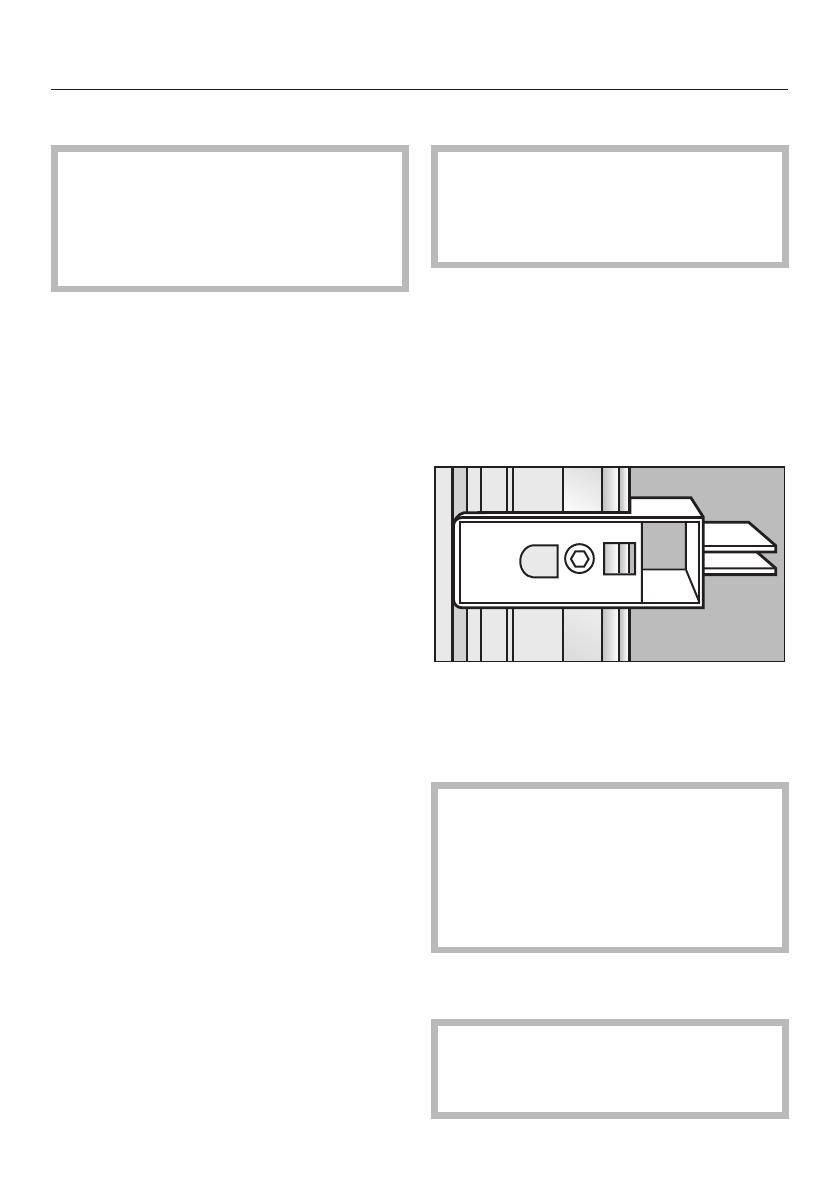
Check the location of the power
outlet.
^ Check the location of the water
connection (see "Plumbing").
^ Check that all furniture parts in the
vicinity of the appliance are securely
connected to the wall.
^ Check that the adjacent
furniture/fixtures do not collide with
the open door.
Before installation
,
Caution - the appliance is very
heavy. Use caution when unpacking
and opening the door, danger of
tipping.
^
To protect the base from damage
during installation, attach a hard
board, linoleum, etc., to the floor in
front of the intended installation
location.
^
Take the supplied accessories out of
the protective packaging.
^ Do not remove the installation
supports from the appliance door.
They will be used later in the
installation niche.
There are transportation safety
devices inside the appliance to
protect the shelves and storage
compartments until installation is
complete. Do not remove them,or
parts may be damaged.
^
Check the appliance for damage in
transit.
Do not install the appliance if it is
visibly damaged. If in doubt, contact
your dealer.
Installing the appliance
59
^
Loosen the bracket that holds the
appliance to the pallet.
,
Caution! The appliance is no
longer secured and may be
unstable.
^ From the rear of the appliance
carefully lift it from the pallet.
Once the appliance is on the ground it
can be wheeled around.
RemoteVision module
installation
Always disconnect the appliance
from the power supply when
performing installation, maintenance
or service work.
Install the RemoteVision module
before placing the appliance in its
installation niche.
Once connected the RemoteVision
modeul will increase the energy
consumption of the appliance.
The slot for the RemoteVision module is
located in the lower area of the back of
your appliance.
^
Unscrew the screws a on the cover
b and pull off the sticker c.
^
Remove the cover b.
^
Push the module into the slot until it
locks into place.
Installing the appliance
60
^
Connect the appliance to the power
supply and turn it on. After several
seconds the indicator light will come
on.
The indicator light will display different
colors one after the other; any control
light at the end indicates that the
module was correctly installed.
If the indicator light does not come on,
installation of the module was
unsuccessful. In that case, repeat the
process. If that does not correct the
problem, contact Miele.
^
Pull the antenna d straight out.
^
Guide the cover b over the antenna
d and screw on the cover.
^
Angle the antenna d so that it faces
to the right or left.
If necessary, disconnect the power
supply and continue installing the
appliance.
Preparing the installation
niche
Keep the appliance door closed
until it is securely fastened in the
niche. Tipping hazard.
If the installation niche is deeper than
the appliance, a solid wooden beam a
can be placed behind the anti-tip
brackets b so the appliance can be
securely attached to the base or wall.
The length of the wooden beam a
should be to the width of the installation
space.
If possible, always screw the
wooden beam into existing studs.
Installing the appliance
61
Anti-tip brackets
The anti-tip brackets help keep the
appliance safely secured to the
installation niche to prevent tipping.
Two anti-tip brackets are
recommended for each appliance or
appliance combination (side-by-side).
The distance "D" between the anti-tip
brackets b is the width of the
appliance.
^ Position the anti-tip brackets b on
the left and right walls of the
appliance niche.
^ Mark the holes through the anti-tip
brackets b on the floor of the
installation niche.
^
Set the brackets aside.
Assure that there are no electrical
wires or plumbing in the area which
the screws could penetrate - risk of
injury and damage.
^
Drill pilot holes:
1
/
8
"(3mm)for5x60mmwood
screws
1
/
16
"(2mm)for4x15mmwood
screws
^ Tightly secure the anti-tip brackets in
the niche.
Be certain that the screws penetrate
through the flooring and into the wall
plate a minimum of
3
/
4
" (19 mm).
Installing the appliance
62
Securing an alternative anti-tip
device
If the anti-tip brackets cannot be
attached securely, an alternative
anti-tip device can be used.
Ensure that there is no "give" between
the appliance and the anti-tip device.
If possible, always screw the
wooden beam to existing studs.
^
Cut a wooden beam
(cross section min. 29 ½" x 39
3
/
8
"
[75 cm x 100 cm]) to the required
length.
The length is equal to the width of the
installation niche.
If the installation niche is deeper than
the appliance, select a beam with a
larger cross section, or attach two
beams.
The beam must cover the appliance
by at least 2" (50.8 mm).
^
Mark the installation height (lower
edge of the beam) on the rear wall of
the niche.
^
Select screws according to the
thickness of the wooden beam.
Example: 3 ½" screw for 2x4 beam.
^
Determine the number of screws
based on the cavity width, to ensure
that the beam will be attached
securely.
^
Locate wall studs near the rear wall
of the cavity and mark drill holes in
the beam.
^ Pre-drill the wooden beam.
^ Attach the wooden beam to the rear
wall of the niche.
If a side-by-side installation is
desired, connect the two appliances
together. See the Installation Manual
included with the "Merging Kit".
Now prepare the water connection from
the appliance to the main supply line
(see "Plumbing").
Installing the appliance
63
Sliding the appliance into the
installation niche
^ Unscrew the plinth.
^
To protect the corners of the
installation space, attach the
supplied edge protector a on both
sides with adhesive tape.
^
Plug the appliance into the power
outlet b.
In the case of side-by-side
installations, a separate outlet must
be used for each appliance.
^
To prevent the power cord from
becoming caught:
Tie a piece of string to the middle of
the power cord and feed it forward
under the appliance. When sliding
the appliance in, pull the cable
forward c.
^
Carefully slide the appliance into the
space until the height-adjustable
wheels interlock with the anti-tip
brackets d.
If resistance is felt when attempting to
slide the appliance into the installation
niche - for example, because the floor
is uneven,
^ Turn the rear adjustable wheels
slightly outward (see "Aligning the
appliance"), then push the appliance
in.
Be careful not to damage the water
pipe or power cord attached to the
floor.
^
Remove the edge protector a.
Installing the appliance
64
Aligning the appliance
^
Align the appliance with the custom
front.
The installation aids e have been
designed for the following total
thicknesses of custom doors:
3
/
4
" (19 mm)
–1
1
/
2
" (38 mm)
Be sure to take into account the
possible differing thicknesses of the
custom door that is to be fitted
subsequently.
The height-adjustable feet at the front
and rear can all be adjusted from the
front.
Front: with an open-ended wrench
½" (SW 13).
The feet can be adjusted from the
top and bottom f.
Rear: with a
5
/
16
" (8 mm) hex nut
driver via flexible shaft g.
A mark is located on the appliance
base and is used as a standard gauge
for height adjustment. When adjusting
the height, align this mark at 1
1
/
4
"
(32 mm) above the floor.
^
Place a marking-out level over the
installation aids e on the door.
^
Unscrew the height-adjustable feet
until the mark on the base has
reached the indicated guide
dimension 1
1
/
4
" (32 mm).
It is very important to comply with
this dimension for the subsequent
alignment of the custom door fronts.
^
Align the custom door with a level.
Installing the appliance
65
Note:
Do not twist or jam the appliance
inside the niche. When unscrewing
the height-adjustable feet, proceed
gradually, alternating between left
and right.
The adjustment of the rear feet is
aided if the appliance is lifted at the
rear (tipped forward slightly).
If using a wooden beam as an
alternative anti-tip device, rotate the
appliance all the way toward the
wooden beam.
Do not use a power tool to adjust the
rear feet!
Attaching the appliance to the
installation niche
^
Screw the attachment plate lugs h to
the overhead furniture/fixtures.
If there is no way to attach the top of
the appliance, it can be attached to the
sides of the installation niche.
^ Pull out the plate side lugs i.
^ Secure the attachment plate side lugs.
If there is a fairly large gap above the
appliance, cut a wooden beam to fit
exactly and place it in the gap.
^
If necessary, shorten the filler strip j
to the required height.
^
Place the 2 strips on top of each
other k.
^
Insert the filler strip until you hear it
click into place l.
Installing the appliance
66
For a side-by-side combination the filler
strips from both appliances are put
together to form one long filler strip:
^
Take the peg from the "side-by-side
merging kit" and insert it halfway into
the filler strip rail on the left-side
appliance.
^ Place the second filler strip on the
peg and press both filler strips
together.
^ Insert both filler strips into the
installation space above the
appliance, until they click into place.
^
Open the appliance door.
^ Screw the attachment plate lugs m to
the adjacent furniture/fixtures.
If a side-by-side installation is desired,
connect the two appliances together.
See the Installation Manual included
with the "Merging Kit".
Now connect the water supply to the
appliance (see "Plumbing").
Installing the appliance
67
  • Page 1 1
  • Page 2 2
  • Page 3 3
  • Page 4 4
  • Page 5 5
  • Page 6 6
  • Page 7 7
  • Page 8 8
  • Page 9 9
  • Page 10 10
  • Page 11 11
  • Page 12 12
  • Page 13 13
  • Page 14 14
  • Page 15 15
  • Page 16 16
  • Page 17 17
  • Page 18 18
  • Page 19 19
  • Page 20 20
  • Page 21 21
  • Page 22 22
  • Page 23 23
  • Page 24 24
  • Page 25 25
  • Page 26 26
  • Page 27 27
  • Page 28 28
  • Page 29 29
  • Page 30 30
  • Page 31 31
  • Page 32 32
  • Page 33 33

Miele Freezer F1471Vi User manual

Category
Fridge-freezers
Type
User manual
This manual is also suitable for

Miele Freezer F1471Vi: Experience the pinnacle of food preservation with our cutting-edge freezer, designed to keep your frozen goods fresh and delicious. Equipped with innovative features, it offers exceptional convenience and peace of mind.

Ask a question and I''ll find the answer in the document

Finding information in a document is now easier with AI