Page is loading ...

4007448-10
Hot glass
will cause burns.
Do not touch glass
until cooled.
Never allow children
to touch glass.
A barrier designed to reduce
the risk of burns from the hot
viewing glass is provided with this
appliance and must be installed for
the protection of children and
other at-risk individuals.
DANGER
WARNING:
FIRE OR EXPLOSION HAZARD
Failure to follow safety warnings
exactly could result in serious
injury, death, or property damage.
Do not store or use gasoline or other
fl ammable vapors and liquids in the
vicinity of this or any other appliance.
WHAT TO DO IF YOU SMELL GAS
▪Do not try to light any appliance.
▪Do not touch any electrical switch; do
not use any phone in your building.
▪Leave the building immediately.
▪Immediately call your gas supplier from
a neighbor’s phone. Follow the gas
supplier’s instructions.
▪If you cannot reach your gas supplier,
call the fi re department.
Installation and service must be
performed by a qualifi ed installer, service
agency or the gas supplier.
Gravity Vent Insert Gas Fireplace
natural gas 738KN
propane gas 738KP
Installation Manual
G3
Installer: Leave this manual with the appliance.
Consumer: Retain this manual for future reference.
Installer: Place model/serial number here.

2
Ce guide est disponible en français sur demande.
This appliance is a domestic room-
heating appliance. It must not be used
for any other purposes such as drying
clothes, etc.
This appliance is suitable for
installation in a bedroom or bed
sitting room.
This manual contains instructions to
install the ENGINE ONLY. A trim kit is
REQUIRED to complete the installation.
A barrier screen is provided with the
trim kit. Refer to the manual supplied
with the trim for installation.
The information contained in this manual is believed to
be correct at the time of printing. Miles Industries Ltd.
reserves the right to change or modify any information
or specifications without notice. Miles Industries Ltd.
grants no warranty, implied or stated, for the installation
or maintenance of your heater, and assumes no
responsibility for any consequential damage(s).
© Copyright Miles Industries Ltd., 2023. All rights reserved.
Designed and manufactured for Miles Industries Ltd.
Valor Fireplaces
190–2255 Dollarton Highway
North Vancouver, BC, Canada V7H 3B1
T 604.984.3496 F 604.984.0246
valorfi replaces.com
This appliance may be installed in an
after-market permanently located,
manufactured (mobile) home where
not prohibited by local codes. This
appliance is only for use with the type
of gas indicated on the rating plate.
This appliance is not convertible for
use with other gases, unless a certified
kit is used.
INSTALLER: Leave this manual with the
appliance.
CONSUMER: Retain this manual for
future reference.
Massachusetts:
The piping and final gas connection must be
performed by a licensed plumber or gas fitter in
the State of Massachusetts.
WARNING
This product can expose you to chemicals
including Benzene, which is known to the State
of California to cause cancer and birth defects or
other reproductive harm. For more information
go to www.P65Warnings.ca.gov.
Note: Natural gas, in its original state, contains
Benzene.

3
Please read this manual BEFORE
installing and operating this
appliance.
This appliance has been professionally installed by:
Dealer Name: ________________________________
Phone:______________________________________
Welcome to Valor®
Fireplace Safety ................................................. 4
Specifi cations ..................................................... 6
Kits and Accessories.......................................... 7
Dimensions ......................................................... 8
Clearances .......................................................... 9
Installation Planning ....................................... 10
Before Installation ......................................................10
Concep t ......................................................................... 11
Venting .............................................................. 12
Preparation ...................................................... 13
Existing Fireplace ........................................................13
Installation ....................................................... 14
Win dow .........................................................................14
Appliance and Venting ...............................................15
Gas Supply ....................................................................16
Liners ............................................................................17
Fuel Bed Support ........................................................18
Fuel Beds ......................................................................19
Traditional Log Kit 739TLK ........................................19
Rock Set Kit 739RSK ...................................................22
Driftwood Kit 739DWK ..............................................24
Legend Traditional Logs 739LSK ..............................26
Window Re-Installation and Checking ................... 28
Batteries and Remote Control ................................. 29
Install Battery Holder ................................................29
Synchronize Remote Control ....................................29
Check Operation and Aeration ................................ 30
Front / Trim ................................................................. 31
Wiring Diagram ................................................ 32
Appendix A—Lighting Instructions ............... 33
Appendix B—Remote Control Operation .... 34
Appendix C—Spare Parts ............................... 38

4
Fireplace Safety
This manual contains very important information about the safe installation and operation of the fi replace. Read and
understand all instructions carefully before installing and operating the fi replace. Failure to follow these instructions
may result in possible fi re hazard and will void the warranty.
Replacement manuals are available by contacting the Valor Customer Service at 1-800-468-2567, or by visiting
valorfi replaces.com.
Do not put
furniture or other objects
in this space in front of
WKHȴUHSODFH
36” [0.9 m]
)LUHSODFH
Hearth
WARNING: Extremely Hot!
Heat and fl ammability
• Some parts of the fi replace are extremely hot, particu-
larly the glass window. Use the barrier screen provid-
ed or a gate to reduce the risk of severe burns.
• The glass windows can exceed 500°F at full capacity.
• Always keep the appliance clear and free from com-
bustible materials, gasoline, and other fl ammable
vapors and liquids.
• Be aware of hot wall surfaces! The wall directly above
the fi replace can get very hot when the fi replace
heats. Although safe, it may reach temperatures in ex-
cess of 200ºF (93°C) depending on choice of optional
accessories. Do not touch!
• Be aware of hot shelf/hearth/fl oor surfaces! Any
projections directly around the fi replace can get very
hot when the fi replace heats. Although safe, they may
reach temperatures in excess of 200ºF (93°C) depend-
ing on their elevation. Be careful of touching these! Do
not put objects on the hearth or shelf. Temperature
of projection surfaces will be reduced when barrier
screen is installed.
• Some materials or items, although safe, may discolor,
shrink, warp, crack, peel, and so on because of the
heat produced by the fi replace. Avoid placing candles,
paintings, photos and other combustible objects
sensitive to heat or furniture within 36 inches (0.9m)
around the fi replace.
• Solid wood fl ooring in front of the fi replace (if allowed)
may shrink during the heating season due to heat.
• Due to high temperatures, the appliance should be
located out of traffi c areas and away from furniture
and draperies.
• Clothing or other fl ammable material should not be
placed on or near the appliance.
Barrier Screen and Safety
• A barrier designed to reduce the risk of burns from
the hot viewing glass is provided with this appliance
and must be installed for the protection of children
and other at-risk individuals.
• Children and adults should be alerted to the hazards
of high surface temperature and should stay away to
avoid burns or clothing ignition.
• Young children should be carefully supervised when
they are in the same room as the appliance. Toddlers,
young children, and others may be susceptible to
accidental contact burns. A physical barrier is recom-
mended if there are at-risk individuals in the house. To
restrict access to a fi replace or stove, install an adjust-
able safety gate to keep toddlers, young children, and
other at-risk individuals out of the room and away
from hot surfaces.
• Any safety screen, guard, or barrier removed for ser-
vicing an appliance, must be replaced prior to operat-
ing the appliance.

5
Fireplace Safety
Glass window
• The glass front assembly must be in place before the
unit can be placed into safe operation.
• The glass front assembly must only be replaced as a
complete unit, as supplied by the fi replace manufac-
turer. No substitute material may be used.
• Do not use abrasive cleaners on the glass front as-
sembly. Do not attempt to clean the glass when it is
hot.
Venting
• This unit must be used with a vent system as de-
scribed in this manual. No other vent system or com-
ponents may be used.
• Never obstruct the fl ow of combustion and ventilation
air. Keep the front of the appliance clear of all obsta-
cles and materials for servicing and proper operation.
• This gas fi replace and vent assembly must be vented
directly to the outside and must never be attached to
a chimney serving a separate solid fuel burning ap-
pliance. Each gas appliance must use a separate vent
system. Common vent systems are prohibited.
Intended use
• This appliance is designed and approved as a supple-
mental heater and provides the potential for most
energy conservation when used while attended. The
use of an alternate primary heat source is advisable.
• This unit is not for use with solid fuel.
• Do not use this heater as a temporary source of heat
during construction.
Installation and Servicing
• Installation and repair should be done by a qualifi ed
service person. The appliance should be inspected
before use and at least annually by a professional
service person. More frequent cleaning might be
required due to excessive lint from carpeting, bedding
material, et cetera. It is imperative that control com-
partments, burners, and circulating air passageways
of the appliance be kept clean.
• Do not use this appliance if any part has been under
water. Immediately call a qualifi ed service technician
to inspect the appliance and to replace any part of the
control system and any gas control that has been
under water.
WARNING
Do not operate this appliance with the
glass front removed, cracked, or broken.
Do not strike or slam the glass front.
Replacement of the glass front should
be performed by a licensed or qualified
service person.

6
Specifications
Approval & Codes
This appliance is certified to ANSI Z21.88/CSA 2.33
American National Standard / CSA Standard for Vented
Gas Fireplace Heaters for use in Canada and USA, and
to CGA 2.17-91 High Altitude Standard in Canada. This
appliance is for direct vent installations.
This appliance complies with CSA P.4.1-15 Testing
method for measuring annual fireplace efficiencies.
The installation must conform to local codes or, in
the absence of local codes, with the National Fuel Gas
Code, ANSI Z223.1/NFPA 54 or the Natural Gas and
Propane Installation Code CAN/CGA-B149.1. Only
qualified licensed or trained personnel should install this
appliance.
This appliance must be electrically grounded in
accordance with local codes, or, in the absence of local
codes, with the National Electrical Code, ANSI/NFPA 70
or the Canadian Electrical Code, CSA C22.1.
Ratings
*High Altitude Installations
Input ratings are shown in BTU per hour and are
certified without deration for elevations up to 4,500 feet
(1,370 m) above sea level.
For elevations above 4,500 feet (1,370 m) in USA,
installations must be in accordance with the current
ANSI Z223.1 and/or local codes having jurisdiction.
Heating value of gas in some areas is reduced to
compensate for elevation—consult your local gas utility
to confirm.
For installations at elevations above 4,500 feet (1,370 m)
in Canada, please consult provincial and/or local
authorities having jurisdiction.
Supply Gas
Heater engine 738KN uses natural gas.
Heater engine 738KP uses propane gas.
The supply pressure must be between the limits shown
in the Ratings section.
The supply connection is 3/8” NPT female and located
on the left side of the control valve. The gas line entry
point is on the left hand side on the fireplace.
See Gas Supply Installation section for details.
Electrical
The 738K is designed to run on battery power and does
not require an electrical source to operate as a heater.
Conversion Kits
The 738K is supplied as natural gas or propane gas
and is field convertible between fuels. See instructions
packaged with the conversion kits for further
information.
Floor/Hearth
This appliance is approved for installation into existing
solid-fuel burning fireplaces only. Provided leveling
screws or combustible material such as plywood and
so on may be used for leveling and shimming beneath
the unit. This appliance does not require a hearth other
than to support the weight of certain fronts.
Outdoor Conversion Kit
The 738K models are supplied standard for indoor
applications and may be adapted for installation in
specific “outdoor” applications protected from weather
as defined in the GV60CKO outdoor conversion kit
manual.
X
Model 738KN 738KP
Gas Natural Propane
Altitude (Ft.)* 0-4,500 feet*
Input Maximum (Btu/h) 24,000 24,000
Input Minimum (Btu/h) 6,500 13,000
Manifold Pressure (in w.c.) 3.95” 9.5”
Minimum Supply Pressure (in
w.c.) 5” 11”
Maximum Supply Pressure (in
w.c.) 10.5” 14”
Main Burner Injector Marking 82-650 92-260
Pilot Injector Marking 35 27
Min. Rate Bypass Screw 125 125
NOTE
This appliance is designed and approved as a
supplemental heater and provides the potential
for most energy conservation when used while
attended. The use of an alternate primary heat
source is advisable.

7
Kits and Accessories
Information accurate at the time of printing and subject to change without notice.
Required Kits Optional Accessories
Fuel Beds (choose one)
739TLK Traditional Log Kit
739RSK Rock Set
739DWK Driftwood Kit
Liners (choose one)
739RGL Refl ective Glass Panels
739FBL Fluted Black Panels
739VRL Valor Red Brick Panels
Inner Fronts (choose one) Barrier
Screen
741 Contemporary Steel Front 4003360
742 Traditional Cast Front 4003293
743 FenderFire Double Door w/Doors
744 FenderFire Single Door
745 Clearview Front 4003313
Outer Surrounds, Trims, and Frets
See your dealer for your choice of Outer Surrounds, Trims, and
Frets.
Gas Conversion Kits
738KNGK Conversion Kit to Natural Gas
738KPGK Conversion Kit to Propane Gas
Other Accessories
770ZCK Zero Clearance Kit
1265WSK Wall Switch Kit
GV60CKO Outdoor Fireplace Conversion Kit
Hearth Gate
Hearth gates such as Cardinal’s VersaGate
are available at retail stores carrying safety
products for children.

8
28-5/8” (727 mm)
19-1/2” (495 mm)
7-7/8” - 9-7/8“
(200 - 251 mm)
Varies with
outer trim options
20”
(508 mm)
Gas inlet Gas connection
Optional Outer Trim or
Surround sold separately
See table below
for minimum
cavity dimensions
Dimensions
Top View
Dimensions
Front ViewLeft Side View Right Side View
Minimum Cavity Dimensions
Check that masonry step does not interfere with install
dimensions or vent pipe.
If mantel is combustible, see the following section for
allowable clearances.
X
Y
Cavity
Outer Trims
746CTK, 748CTK,
756ST, 767STB,
757ST, 715CV
747DTK, 753OTK
Minimum Depth (X) 12-7/8”
[327 mm]
12-1/4”
[312 mm]
Minimum Height (Y) 20-1/2”
[521 mm]
20-1/2”
[521 mm]
Minimum Width 28”
[711 mm]
28”
[711 mm]

9
Combustible Mantel Clearances
*Measure taken from the underside of the mantel to
finished hearth or surface that the unit is sitting on.
Finishing Materials
Combustible materials: Materials made of or surfaced
with wood, compressed paper, plant fibers, plastics, or
other material that can ignite and burn, whether flame
proofed or not, or plastered or unplastered.
Non-combustible materials: Material which will not
ignite and burn. Such materials are those consisting
entirely of steel, iron, brick, tile, concrete, slate, glass or
plasters, or any combination thereof.
Materials that are reported as passing ASTM E 136,
Standard Test Method for Behavior of Materials in a
Vertical Tube Furnace at 750 °C
Minimum distance from side of appliance (liner box) to
combustible wall: 9” [229 mm]. Mantel legs projecting
forward less than 6” (152 mm) may be located within 5”
(127 mm) of the side of the appliance (liner box).
Floor/Hearth Clearances
Combustible shims/supports or provided leveling
screws may be used beneath the appliance to level or
raise the appliance within the existing fireplace cavity.
Combustible flooring/hearths in front of the appliance
are allowed provided they are no higher than the base
of the appliance. Carpet, vinyl flooring should be kept
back to a minimum of 12” (305 mm) from the front of
the insert. The gas insert does not require a hearth.
9” (229 mm)
sidewall
A
B
Do not put
furniture or
objects within
36” (914 mm)
of the front of
appliance
Mantel
Projection A
1”
[25 mm]
1-6”
[25-152 mm]
9”
[229 mm]
12”
[305 mm]
Mantel
Height B*
36”
[914 mm]
39”
[991 mm]
42”
[1067 mm]
45”
[1143 mm]
Clearances Mantel and Sidewall
Sidewall Clearances
WARNING
Some materials or items, although
safe, may discolor, shrink, warp,
crack, peel, and so on because of the
heat produced by the fireplace. Avoid
placing candles, paintings, photos, and
other items sensitive to heat around
the fireplace.
WARNING
HOT GLASS! The use of a screen in front
of the glass is highly recommended
particularly in households with
children.
WARNING
HOT HEARTH / FLOOR! The hearth
or floor in front of the fireplace may
become very hot when the fireplace
heats. Do not use the hearth as a seat
or shelf. Solid wood flooring in front of
the fireplace (if allowed) may shrink
during the heating season due to heat.

10
Installer - READ THIS FIRST!
1. YOU NEED TO KNOW FROM THE HOMEOWNER:
• What accessories (surround, screen, ZC kit, etc.)
will be installed
2. Unpack the appliance, removing all items packed
inside and around it. Recycle the packaging.
3. Check that you have everything, using the Pack Con-
tent sheet. Also, check that you have:
• Fuel bed (packed separately)
• Liner panels (packed separately)
• Optional accessories (if ordered)
• Gas conversion kit (if necessary)
• Venting accessories
4. Carefully read the Installer’s Checklist included with
the fi replace for the installation sequence.
Caution
Only qualified, licensed, or trained personnel
should install this appliance.
Installation Planning Before Installation

11
This appliance, as supplied, may ONLY be installed in an existing unaltered, functioning solid-fuel burning
fireplace with a working flue and constructed of non-combustible material.
This appliance may be installed in outdoor, weather-protected environments as defined in the GV60CKO
Outdoor Conversion Kit instruction manual.
This appliance is APPROVED for installation into combustible type construction only when using the 770ZCK—
Zero Clearance Kit (see separate instructions packaged with the kit for details).
Installation Planning Concept
WARNING
Some materials or items, although safe,
may discolor, shrink, warp, crack, peel,
and so on because of the heat produced
by the fireplace. Avoid placing candles,
paintings, photos, and other items
sensitive to heat around the fireplace.
WARNING
HOT HEARTH / FLOOR! The hearth or floor
in front of the fireplace may become very
hot when the fireplace heats. Do not
use the hearth as a seat or shelf. Solid
wood flooring in front of the fireplace (if
allowed) may shrink during the heating
season due to heat.
738 fireplace
Chimney
Terminal Cap
Flashing
Approved 3”
flex chimney
liner running
full length
Existing
unaltered,
functioning
solid-fuel
burning
fireplace &
chimney
Existing non-combustible
hearth.
Outer trim
(Optional, sold separately)
Fret
(Optional, sold separately)
Inner front with barrier screen
(Required, sold separately)

12
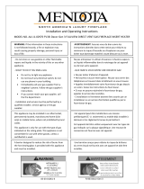
Vent Location
The vent terminal must be located through the roof. This gravity
vent appliance is designed to operate when an undisturbed
airflow hits the outside vent terminal from any direction.
Check local codes for allowable vertical vent termination.
Vent Materials
Use a 3” diameter aluminum flex liner approved for gas venting
when installed as an insert (existing chimney). Use a 4” diameter
type “B” vent when installed with a 770ZCK Zero Clearance Kit
(see separate instructions packaged with the kit for details).
Venting Notes
Where possible, avoid joining flex pipes. If joints are required, use
a approved connector and seal joints with RTV high temp sealant.
Horizontal offsets are permissible to allow for routing around
masonry projections. Avoid bending flex pipe over a 45 degrees
radius where possible.
Terminal Cap
Flashing
3” fl ex liner
Venting Concept
Typical Vent Installation
Approved Termination Required
Max. 36” offset at 10’-0” min. vertical
3” Liner
3” min. Bend
Radius
Min. 10 feet (with offset)
Min. 8 feet (without offset)
Minimum Vent Liner Radius
Allowable Vent Configurations
Minimum vent lengths.
For other allowable configurations,
refer to the venting tables in the
National Fuel Gas Code Z223.1 or the
Natural Gas or Propane Installation
Code B149.1.

13
Preparation Existing Fireplace
Existing Fireplace Preparation
A few points must be considered before inserting
the 738 into an existing fi replace cavity. Generally, no
modifi cations are allowed to the existing fi replace that
will compromise the integrity of the existing fi replace.
Components that are bolted or screwed on such as
dampers or baffl es may be removed to accommodate
the installation of the 738 engine. Cutting away any
sheet metal parts of the existing fi replace to accommo-
date the installation of the 738 is prohibited. Check with
local authorities if in doubt.
Clean Fireplace and Chimney
Have the chimney swept and the fi replace cavity
including ash dumps and clean-outs cleaned before
installing the 738 heater and vent liners. Any creosote
or soot residue remaining in the fi replace cavity chim-
ney or clean-out may cause odors or stains once the
738 insert is installed. Consult with chimney sweep for
information on how best to clean.
Existing Dampers
Factory-built, zero-clearance fireplaces will require the
damper to be removed in order to install the vent liners.
These dampers are usually bolted into place. Dampers
in masonry fireplaces must be fixed open and may
remain in place.
Ash Retaining Curbs
Some fi replaces (particularly factory-built) have a raised
curb at the front edge to retain ashes. Check the dimen-
sions carefully to ensure the 738 engine will fi t behind
any raised curb (some curbs may be removed separate-
ly from the refractory base).
Gas Line Routing
Plan the routing of the gas line before proceeding.
Utilize the existing hole for the gas line of the factory-
built fireplace.
If the fireplace has no access hole, carefully drill an
access hole of 1.5 inch (38 mm) or less through the
lower sides or bottom of the firebox. The access hole
must be plugged with non-combustible insulation after
the gas supply line has been installed.
See Dimensions section for detailed location of gas inlet.
Also, take into consideration whether or not a fan or
shut-off valve will interfere when planning routing of the
gas line.
Existing Glass Doors and Wire Screens
Existing glass doors must be permanently removed
prior to installing the 738 insert.
Combustible Mantels
Combustible mantel clearances must conform to those
required for the original solid-fuel fireplace into which
the 738 is being installed.
Attach Warning Conversion Plate to Existing
Fireplace
(plate supplied loose with 738 heater)
Attach the “This fireplace has been converted...” label to
the existing fireplace using screws or other mechanical
means and store any removed parts in back of the
existing fireplace for future use.

14
Installation Window
Remove Window
The window is held in place by four spring-loaded bolts,
two at the top and two at the bottom.
1. To remove the window, turn each bolt a quarter
turn to disengage the bolt pin.
2. Gently pull the bottom of the window outward and
unhook it from the fi rebox’s opening frame.
3. Set the window aside in a safe place to avoid dam-
age.

15
Connect Venting and Insert Appliance
IMPORTANT: This appliance’s venting system require room
air to be used in the combustion process.
1. Rough-in one 3” diameter vent liner into the existing
chimney system from the roof. Be careful not to tear or
damage the liner in the process. Leave plenty of liner
at the bottom to facilitate the connection of the liner to
the vent slider. It is best to leave the top termination
until later.
2. Release the two screws retaining the vent slider to the
front of the fi rebox. Remove the slider from the fi rebox
by sliding it towards the back of the fi rebox.
3. Secure the liner to the collar on the vent slider using the
hose clamp (included) and 2 tapping screws per liner.
4. Slide the fi rebox onto the vent slider in the cavity tak-
ing care not to damage the liner. Make sure that the
vent slider is pulled all the way forward. Secure the
vent slider to the front of the fi rebox with two screws
removed earlier.
5. From the roof, pull the liner and fi t the fl ashing.
6. Fit the terminal cap. Secure with screws.
7. Seal the terminal and fl ashing from water penetration
as required.
4
1
3
5
6
2
7
Installation Appliance and Venting
WARNING
Failure to position the parts in
accordance with these diagrams
or failure to use only parts
specifically approved with this
appliance may result in property
damage or personal injury.

16
Connect Gas Supply
The gas supply inlet connection is a 3/8” NPT female
connector andis located on the left hand side of the
control valve.
Use only new black iron or steel pipes, CSST, or copper
tubing if acceptable—check local codes. Note that
in USA, copper tubing must be internally tinned for
protection against sulfur compounds.
The burner platform and gas train on this appliance
may be removed as a unit for servicing or to install or
remove the optional circulating fan (if installed). Provide
some form of pipe union (depending on type of piping)
as close as possible to appliance valve.
Unions in gas lines should be of ground joint type.
The gas supply line must be sized and installed to
provide a supply of gas sufficient to meet the maximum
demand of the appliance without undue loss of
pressure.
Sealant used must be resistant to the action of all gas
constituents including LP gas. Sealant should be applied
lightly to male threads to ensure excess sealant does
not enter gas lines.
Pressure test the supply line for leaks.
The appliance and its individual shut-off valve must be
disconnected from the gas supply piping system during
any pressure testing of that system at test pressures in
excess of 1/2 psig (3.5 kPa).
The appliance must be isolated from the gas supply
piping system by closing its equipment shut-off valve
during any pressure testing of the gas supply piping
system at test pressures equal to or less than 1/2 psi
(3.5 kPa).
Failure to either disconnect or isolate the appliance
during pressure testing may resulting regulator or valve
damages and void the warranty. Consult your dealer in
case of damages.
X
Pressure Test Points
The minimum supply pressure is given in the section
Specifications of this manual— page 6.
All piping and connections must be tested for leaks after
installation or servicing. All leaks must be corrected
immediately.
When testing for leaks:
• Make sure that the appliance is turned off .
• Open the manual shut-off valve.
• Test for leaks by applying a liquid detergent or soap
solution to all joints. Bubbles forming indicate a gas
leak.
The pressure test tapping locations are shown in the
figure below. An internal regulator within the valve
controls the burner manifold pressure.
The correct pressure range is shown in the table in
section Specifications of this manual on page 6.
The pressure check should be made with the burner
alight and at its highest setting. See Lighting Instructions
section for full operating details on page 33.
Supply
pressure
test tapping
Manifold
pressure
test tapping
Pressure Testing
Control
Valve
Manifold Pressure Adjustment
behind Plastic Cap
WARNING
NEVER USE open flame to check for leaks.
Correct any leak detected immediately.
Installation Gas Supply

17
Liner Installation
The following guidelines apply for all liners except the
739RGL Reflective Glass Liners which require some
preparation prior to installation—see instructions
packed with liners.
1. Inside the fi rebox, on the top of each side, release
the screw of the side brick anchors (one per side)
just enough to allow them to rotate.
2. Place the rear panel against the back of the fi rebox,
on the ledge at bottom.
3. Rotate the anchor up and out of the way and slide
the left hand side panel against the fi rebox side. The
panel should be parallel to the edge of the burner
plate. Rotate the anchor back down to hold the
panel.
Rotate anchor up and
insert panel Position of panel in
relation to burner
plate
Edge of
burner plate
Side panels
should be
parallel to
edge of
burner plate
4. Rotate the anchor up and out of the way and slide
the right hand side panel against the fi rebox side.
The panel should be parallel to the edge of the
burner plate. Rotate the anchor back down to hold
the panel.
5. Tighten the side brick anchors on each side of the
fi rebox.
Installation Liners

18
Installation Fuel Bed Support
Adjust Fuel Bed Support (if necessary)
The appliance is supplied a the fuel bed support with
an adjustable bracket already installed in a specific
position.
Unless otherwise indicated in the fuel beds’ installation
instructions, an adjustment is not necessary.*
If desirable, the position of the bracket can be changed
by releasing its 3 retaining screws, moving it as required
and tightening the screws.
Moving the bracket forward will allow more
impingement/glow/flame height; moving the bracket
backward will do the opposite.
*The adjustable bracket of the fuel bed support will
need to be replaced by a different one to install the
Traditional Logs Kit 739TLK. This bracket is included
loose with the logs or the appliance. See 739TLK
installation instructions.

19
Installation Fuel Beds
Traditional Log Kit 739TLK
Material required
• Traditional Log Kit, which contains:
• 6 logs
• 3 embers
• 1 support bracket - log, supplied with logs
or fi replace
Installation
Carefully unpack the kit. Note each log has its own
number stamped on the bottom. Some logs have pegs
to help you place them on the burner platform, or other
logs.
Replace Fuel Bed’s Support Bracket
The fireplace is supplied with the fuel bed support
and bracket shown below. For this log set, the support
bracket must be replaced by the bracket included loose
either with the log set or the fireplace.
1. Remove the factory-installed fuel bed’s support
bracket (3 screws).
2. Install the support bracket supplied loose with the
log set or fi replace, securing it re-using the same
screws. Ensure the screws are centered in the
bracket’s slots as shown.
G30
G31
G32
G33 G34
Base Panel
Embers

20
Installation Fuel Beds
Logs
1. Place log G30 on the fuel bed support; slide it left
against the pilot shield. The front tabs of the sup-
port should be in the notches of the log.
2. Place the base panel log on top of the burner,
ensuring the vertical fl ange of the burner is inserted
in the groove under the log as indicated.
G30
Base panel
3. Place log G31 from pin on G30 to base panel.
4. Place log G32 from pin on G30 to base panel.
5. Place log G34 from base panel to rest against G30.
6. Place log G33 from base panel to rest against G30,
underneath G31.
G31 G30
G32
G30
G34
G30
G33
G30
G31
/