Page is loading ...

Instructions–Parts List
308118N
EN
SEVERE-DUTY, UHMWPE/PTFE PACKED
Stainless Steel Pumps
55 gallon (200 liter) drum size, with bung adapter.
For transfer and supply of solventborne and waterborne finishing materials.
For professional use only.
Important Safety Instructions
Read all warnings and instructions in this manual.
Save these instructions.
See page 2 for table of contents.
Model 224348, Series C
10:1 Ratio Presidentr Pump
Model 256713, Series A
10:1 Ratio Presidentr Pump (1.5 in. Female Inlet)
1800 psi (12.4 MPa, 124 bar) Maximum Fluid Working Pressure
180 psi (1.25 MPa, 12.5 bar) Maximum Air Inlet Pressure
Model 224350, Series C
5:1 Ratio Monarkr Pump
Model 256714, Series A
5:1 Ratio Monarkr Pump (1.5 in. Female Inlet)
900 psi (6.3 MPa, 63 bar) Maximum Fluid Working Pressure
180 psi (1.25 MPa, 12.5 bar) Maximum Air Inlet Pressure
0200A
MODEL 224348 SHOWN
0359
II 1/2 G T2
ITS03ATEX11228
0359
II 1/2 G T2
ITS03ATEX11228

2 308118
Table of Contents
Warnings 2. . . . . . . . . . . . . . . . . . . . . . . . . . . . . . . . . . . . . .
Installation 5. . . . . . . . . . . . . . . . . . . . . . . . . . . . . . . . . . . . .
Operation 9. . . . . . . . . . . . . . . . . . . . . . . . . . . . . . . . . . . . .
Troubleshooting 13. . . . . . . . . . . . . . . . . . . . . . . . . . . . . . .
Service 14. . . . . . . . . . . . . . . . . . . . . . . . . . . . . . . . . . . . . .
Parts 18. . . . . . . . . . . . . . . . . . . . . . . . . . . . . . . . . . . . . . . .
Technical Data 22. . . . . . . . . . . . . . . . . . . . . . . . . . . . . . . .
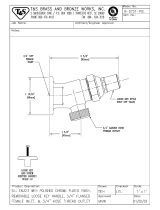
Dimensions 26. . . . . . . . . . . . . . . . . . . . . . . . . . . . . . . . . . .
Mounting Hole Layout 26. . . . . . . . . . . . . . . . . . . . . . . . . .
Warranty 28. . . . . . . . . . . . . . . . . . . . . . . . . . . . . . . . . . . . .
Graco Information 28. . . . . . . . . . . . . . . . . . . . . . . . . . . . .
Symbols
Warning Symbol
WARNING
This symbol alerts you to the possibility of serious
injury or death if you do not follow the corresponding
instructions.
Caution Symbol
CAUTION
This symbol alerts you to the possibility of damage to
or destruction of equipment if you do not follow the cor-
responding instructions.
WARNING
INSTRUCTIONS
EQUIPMENT MISUSE HAZARD
Equipment misuse can cause the equipment to rupture or malfunction and result in serious injury.
This equipment is for professional use only.
Read all instruction manuals, tags, and labels before operating the equipment.
Use the equipment only for its intended purpose. If you are uncertain about usage, call your Graco
distributor.
Do not alter or modify this equipment. Use only genuine Graco parts and accessories.
Check equipment daily. Repair or replace worn or damaged parts immediately.
Do not exceed the maximum working pressure of the lowest rated system component. Refer to the
Technical Data on page 22 for the maximum working pressure of this equipment.
Use fluids and solvents which are compatible with the equipment wetted parts. Refer to the Tech-
nical Data section of all equipment manuals. Read the fluid and solvent manufacturer’s warnings.
Do not use hoses to pull equipment.
Route hoses away from traffic areas, sharp edges, moving parts, and hot surfaces. Do not expose
Graco hoses to temperatures above 82C (180F) or below –40C (–40F).
Wear hearing protection when operating this equipment.
Do not lift pressurized equipment.
Comply with all applicable local, state, and national fire, electrical, and safety regulations.

3308118
WARNING
SKIN INJECTION HAZARD
Spray from the gun/valve, hose leaks, or ruptured components can inject fluid into your body and
cause extremely serious injury, including the need for amputation. Fluid splashed in the eyes or on the
skin can also cause serious injury.
Fluid injected into the skin might look like just a cut, but it is a serious injury. Get immediate surgi-
cal treatment.
Do not point the gun/valve at anyone or at any part of the body.
Do not put your hand or fingers over the spray tip/nozzle.
Do not stop or deflect leaks with your hand, body, glove or rag.
Do not “blow back” fluid; this is not an air spray system.
Always have the tip guard and the trigger guard on the gun when spraying.
Check the gun diffuser operation weekly. Refer to the gun manual.
Be sure the gun/valve trigger safety operates before spraying/dispensing.
Lock the gun/valve trigger safety when you stop spraying/dispensing.
Follow the Pressure Relief Procedure on page 9 whenever you: are instructed to relieve pres-
sure; stop spraying/dispensing; clean, check, or service the equipment; and install or clean the
spray tip/nozzle.
Tighten all fluid connections before operating the equipment.
Check the hoses, tubes, and couplings daily. Replace worn, damaged, or loose parts immediately.
Permanently coupled hoses cannot be repaired; replace the entire hose.
Use only Graco approved hoses. Do not remove any spring guard that is used to help protect the
hose from rupture caused by kinks or bends near the couplings.
MOVING PARTS HAZARD
Moving parts, such as the air motor piston, can pinch or amputate your fingers.
Keep clear of all moving parts when starting or operating the pump.
Before servicing the equipment, follow the Pressure Relief Procedure on page 9 to prevent the
equipment from starting unexpectedly.

4 308118
WARNING
FIRE AND EXPLOSION HAZARD
Improper grounding, poor ventilation, open flames or sparks can cause a hazardous condition and
result in a fire or explosion and serious injury.
Ground the equipment and the object being sprayed. Refer to Grounding on page 5.
If there is any static sparking or you feel an electric shock while using this equipment, stop spray-
ing/dispensing immediately. Do not use the equipment until you identify and correct the problem.
Provide fresh air ventilation to avoid the buildup of flammable fumes from solvents or the fluid
being sprayed/dispensed.
Keep the spray/dispense area free of debris, including solvent, rags, and gasoline.
Electrically disconnect all equipment in the spray/dispense area.
Extinguish all open flames or pilot lights in the spray/dispense area.
Do not smoke in the spray/dispense area.
Do not turn on or off any light switch in the spray/dispense area while operating or if fumes are
present.
Do not operate a gasoline engine in the spray/dispense area.
TOXIC FLUID HAZARD
Hazardous fluid or toxic fumes can cause serious injury or death if splashed in the eyes or on the skin,
inhaled, or swallowed.
Know the specific hazards of the fluid you are using.
Store hazardous fluid in an approved container. Dispose of hazardous fluid according to all local,
state and national guidelines.
Always wear protective eyewear, gloves, clothing and respirator as recommended by the fluid and
solvent manufacturer.

5308118
Installation
Grounding
WARNING
FIRE AND EXPLOSION HAZARD
Before operating the pump, ground the
system as explained below. Also read
the section FIRE AND EXPLOSION
HAZARD on page 4.
To reduce the risk of static sparking, ground the pump.
Check your local electrical code for detailed grounding
instructions for your area and type of equipment. Be
sure to ground all of this dispensing equipment.
1. Pump: loosen the grounding lug locknut (W) and
washer (X). Insert one end of a 1.5 mm
2
(12 ga)
minimum ground wire (Y) into the slot in lug (Z)
and tighten the locknut securely. See Fig. 1. Con-
nect the other end of the ground wire to a true
earth ground. Order Part No. 237569 Ground Wire
and Clamp.
2. Air and fluid hoses: use only electrically conductive
hoses with a maximum of 500 ft (150 m) combined
hose length to ensure grounding continuity.
3. Air compressor: follow manufacturer’s recommen-
dation.
4. Spray gun: grounding is obtained through connec-
tion to a properly grounded fluid hose and pump.
5. Object being sprayed: according to your local
code.
6. Fluid supply container: according to your local
code.
7. All solvent pails used when flushing, according to
your local code. Use only metal pails, which are
conductive, placed on a grounded surface. Do not
place the pail on a non-conductive surface, such
as paper or cardboard, which interrupts the
grounding continuity.
8. To maintain grounding continuity when flushing or
relieving pressure, always hold a metal part of the
spray gun firmly to the side of a grounded metal
pail, then trigger the spray gun.
Fig. 1
W
Y
X
Z
0720

6 308118
Installation
KEY
A Pump
B Pump Runaway Valve
C Air Line Lubricator
D Bleed–Type Master Air Valve (required, for pump)
E Pump Air Regulator
F Air Line Filter
G Bleed–Type Master Air Valve (for accessories)
H Air Supply Hose
J Fluid Drain Valve (required)
K Fluid Filter
L Fluid Supply Hose
M Spray Gun
N Pump Bung Adapter
Y Ground Wire (required; see page 5
for installation instructions)
J
A
B
CD
EF G
H
K
L
M
N
Y
1/2 in. (13 mm)
0808A
Typical Installation

7308118
Installation
NOTE: Reference numbers and letters in parentheses
in the text refer to the callouts in the figures and the
Parts Drawing.
NOTE: Contact you Graco distributor for available
Graco accessories. If you supply your own accesso-
ries, be sure they are adequately sized and pressure-
rated to meet the system’s requirements.
The Typical Installation shown on page 6 is only a
guide for selecting and installing system components
and accessories. Contact your Graco distributor for
assistance in designing a system to suit your particular
needs.
System Accessories
Refer to the Typical Installation on page 6.
WARNING
A bleed-type master air valve (D) and a fluid drain
valve (J) are required in your system. These acces-
sories help reduce the risk of serious injury includ-
ing fluid injection, splashing in the eyes or on the
skin, and injury from moving parts if you are adjust-
ing or repairing the pump.
The bleed-type master air valve relieves air trapped
between this valve and the pump after the air is
shut off. Trapped air can cause the pump to cycle
unexpectedly. Locate the valve close to the pump.
The fluid drain valve assists in relieving fluid pres-
sure in the displacement pump, hose, and gun.
Triggering the gun to relieve pressure may not be
sufficient.
Mounting Accessories
Mount the pump (A) to suit the type of installation
planned. The pump dimensions and mounting hole
layout are shown on page 26.
The pump is supplied with a bung adapter. To mount
the pump, loosen the bung adapter screw and slide the
adapter off the pump. Screw the bung adapter secure-
ly into the bung hole on the cover of the supply drum.
Carefully lower the pump through the bung adapter
and into the drum until it rests on the bottom, then pull
it back up 1/2 in. (13 mm). Tighten the bung adapter
screw to hold the pump in this position. Open the
drum’s vent plug to prevent a vacuum from forming in
the drum.
Air and Fluid Hoses
Be sure all air and fluid hoses are properly sized and
pressure-rated for your system. Use only electrically
conductive air and fluid hoses. Fluid hoses must have
spring guards on both ends.
Connect a electrically conductive fluid hose (L) to the
fluid filter (K), if used, or directly to the pump’s fluid
outlet.
Use a electrically conductive 1/2 in. ID (minimum) air
hose (H) to supply air to the pump.
Air Line Accessories
Install the following accessories in the order shown in
the Typical Installation, using adapters as necessary.
An air line lubricator (C) provides automatic air
motor lubrication.
A bleed-type master air valve (D) is required in
your system to relieve air trapped between it and
the air motor when the valve is closed (see the
WARNING at left). Be sure the bleed valve is easily
accessible from the pump, and is located down-
stream from the air regulator.
A pump runaway valve (B) senses when the
pump is running too fast and automatically shuts off
the air to the motor. A pump which runs too fast can
be seriously damaged.
An air regulator (E) controls pump speed and
outlet pressure by adjusting the air pressure to the
pump. Locate the regulator close to the pump, but
upstream from the bleed-type master air valve.
An air line filter (F) removes harmful dirt and
moisture from the compressed air supply.
A second bleed-type master air valve (G) iso-
lates the air line accessories for servicing. Locate
upstream from all other air line accessories.
Fluid Line Accessories
Install the following accessories in the positions shown
in the Typical Installation, using adapters as neces-
sary:
A fluid drain valve (J) is required in your system
to relieve fluid pressure in the hose and gun (see
the WARNING at left). Install the drain valve point-
ing down, but so the handle points up when
opened.
A fluid filter (K) filters harmful particles from the
fluid.
A spray gun (M) dispenses the fluid. The gun
shown in the Typical Installation is an airless
spray gun.

8 308118
Notes

9308118
Operation
Pressure Relief Procedure
WARNING
SKIN INJECTION HAZARD
Fluid under high pressure can be in-
jected through the skin and cause
serious injury. To reduce the risk of an
injury from injection, splashing fluid, or moving
parts, follow the Pressure Relief Procedure
whenever you:
are instructed to relieve the pressure,
stop spraying,
check or service any of the system equipment,
or install or clean the spray tips.
1. Lock the spray gun trigger safety.
2. Shut off the air to the pump.
3. Close the bleed-type master air valve (required in
your system).
4. Unlock the gun trigger safety.
5. Hold a metal part of the gun firmly to the side of a
grounded metal pail, and trigger the gun to relieve
pressure.
6. Lock the spray gun trigger safety.
7. Open the drain valve (required in your system),
having a container ready to catch the drainage.
8. Leave the drain valve open until you are ready to
spray again.
If you suspect that the spray tip or hose is completely
clogged, or that pressure has not been fully relieved
after following the steps above, very slowly loosen the
tip guard retaining nut or hose end coupling and relieve
pressure gradually, then loosen completely. Now clear
the tip or hose.
WARNING
Moving parts can pinch or amputate your fingers or
other body parts. When air is supplied to the motor,
the air motor piston (located behind the air motor
plates) moves. See Fig. 2. Therefore, never oper-
ate the pump with the air motor plates removed.
Flush the Pump Before Using
The pump is tested with lightweight motor oil, which is
left in to protect the pump parts. If the fluid you are
using may be contaminated by the oil, flush it out with
a compatible solvent before using the pump. If the
pump is being used to supply a circulating system,
allow the solvent to circulate until the pump is thor-
oughly flushed.
WARNING
FIRE AND EXPLOSION HAZARD
For your safety, read the section FIRE
AND EXPLOSION HAZARD on page 4
before flushing and follow all the recom-
mendations given there.

10 308118
Operation
Starting and Adjusting the Pump
WARNING
To reduce the risk of serious injury whenever you
are instructed to relieve pressure, always follow the
Pressure Relief Procedure on page 9.
See the Typical Installation on page 6. Be sure the
air regulator (E) and bleed-type master air valve (D)
are closed. Do not install the spray tip yet.
Mount the pump on the supply drum. On bung-style
drums, open the vent plug to prevent a vacuum from
forming in the drum. Hold a metal part of the spray gun
(M) firmly to the side of a grounded metal pail and hold
the trigger open. Then open the pump’s bleed-type
master air valve (D). Now slowly open the air regulator
until the pump starts, about 40 psi (280 kPa, 2.8 bar).
Cycle the pump slowly until the air is pushed out and
the pump and hoses are fully primed. Release the
spray gun trigger and engage the safety latch. The
pump should stall against pressure when the trigger is
released.
Relieve the pressure, then install the spray tip in the
gun.
With the pump and lines primed, and with adequate air
pressure and volume supplied, the pump will start and
stop as the spray gun is opened and closed. In a
circulating system, the pump will run continuously and
will speed up or slow down as supply demands until
the air supply is shut off.
Use an adequately sized air regulator (E) to control the
pump speed and the fluid pressure. Always use the
lowest air pressure necessary to get the desired
results. Higher pressures waste fluid and cause pre-
mature wear of the packings and spray tip.
WARNING
To reduce the risk of overpressurizing your system,
which could result in component rupture and cause
serious injury, never exceed the Maximum Incom-
ing Air Pressure given on your pump or in the
Technical Data on pages 22 and 24.
Keep the packing nut/wet-cup (14) filled with Graco
Throat Seal Liquid (TSL) or compatible solvent, to help
prolong the packing life. Adjust the packing nut weekly
so it is just tight enough to prevent leakage; do not
overtighten. See Fig. 2. Always relieve the pressure
before adjusting the packing nut.
Never allow the pump to run dry of the fluid being
pumped. A dry pump will quickly accelerate to a high
speed, possibly damaging itself. A pump runaway
valve (B), which shuts off the air supply to the pump if
the pump accelerates beyond the pre-set speed, is
available. If your pump accelerates quickly, or is run-
ning too fast, stop it immediately and check the fluid
supply. If the supply container is empty and air has
been pumped into the lines, refill the container and
prime the pump and the lines with fluid, or flush and
leave it filled with a compatible solvent. Be sure to
eliminate all air from the fluid system.
Shutdown and Care of the Pump
WARNING
To reduce the risk of serious injury whenever you
are instructed to relieve pressure, always follow the
Pressure Relief Procedure on page 9.
For overnight shutdown, relieve the pressure. Always
stop the pump at the bottom of the stroke to prevent
the fluid from drying on the exposed displacement rod
and damaging the throat packings.
Always flush the pump before the fluid dries on the
displacement rod. Relieve the pressure after flushing.

11308118
Operation
Fig. 2
AIR MOTOR PLATE
14
0200A

12 308118
Notes

13308118
Troubleshooting
WARNING
To reduce the risk of serious injury whenever you
are instructed to relieve pressure, always follow the
Pressure Relief Procedure on page 9.
Before servicing this equipment always make sure to
relieve the pressure.
Check all possible problems and solutions before
disassembling the pump.
Problem
Cause Solution
Pump fails to operate
Restricted line or inadequate air sup-
ply
Clear; Increase air supply.
Insufficient air pressure; closed or
clogged air valves, etc.
Open, clean.
Exhausted fluid supply Refill; purge all air from pump and
fluid lines.
Damaged air valving mechanism;
stalling
Service air motor (see manual
306982 or 307043).
Dried fluid seizure of displacement
rod (1)
Clean, check or replace throat pack-
ings (3, 25); always stop the pump at
the bottom of its stroke and keep the
wet-cup filled with compatible solvent.
Pump operates, but output low on
both strokes
Restricted line or inadequate air sup-
ply
Clear; increase air supply.
Insufficient air pressure; closed or
clogged air valves, etc.
Open, clean.
Exhausted fluid supply Refill; purge all air from pump and
fluid lines.
Clogged fluid line, valves, etc. Clear*.
Packing nut (14) too tight Loosen (see page 10).
Loose packing nut (14) or worn throat
packings (3, 25)
Tighten packing nut (see page 10);
replace throat packings.
Pump operates, but output low on
down stroke
Held open or worn intake valve. Clear; service.
Pump operates, but output low on
up stroke
Held open or worn fluid piston valve
or packings (29, 30)
Clear; service.
Erratic or accelerated operation
Exhausted fluid supply Refill; purge all air from the pump and
fluid lines.
Help open or worn intake valve. Clear; service.
Help open or worn fluid piston valve
or packings (29, 30)
Clear; service.
* To determine if the fluid hose or gun is obstructed, relieve the pressure. Disconnect the fluid hose and place a container at the
pump fluid outlet to catch any fluid. Turn on the air just enough to start the pump (about 20–40 psi [140–280 kPa, 1.4–2.8 bar]). If
the pump starts when the air is turned on, the obstruction is in the fluid hose or gun.

14 308118
Service
Disconnecting the Displacement Pump
WARNING
To reduce the risk of serious injury whenever you
are instructed to relieve pressure, always follow the
Pressure Relief Procedure on page 9.
1. Flush the pump, if possible. Stop the pump at the
bottom of its stroke. Relieve the pressure.
2. Disconnect the air and fluid hoses. Remove the
pump from its mounting. Note the relative position
of the pump’s fluid outlet (R) to the air motor’s air
inlet (S).
3. Unscrew the tie rod locknuts (112) from the tie
rods (102). Remove the cotter pin (109). Unscrew
the displacement rod (1) from the air motor (106).
Carefully pull the displacement pump (101) away
from the air motor (106). Inspect the o-ring (105).
See Fig. 3.
4. Refer to page 15 for displacement pump service.
To service the air motor, refer to the separate air
motor manual (306982 or 307043), supplied.
Reconnecting the Displacement Pump
1. Lubricate the o-ring (105) and check that it is in
place on the displacement rod (1). Orient the
pump’s fluid outlet (R) to the air motor’s air inlet
(S) as was noted in step 2 under Disconnecting
the Displacement Pump. Position the displace-
ment pump (101) on the tie rods (102). Screw the
locknuts (112) onto the tie rods (102) loosely. See
Fig. 3.
2. Screw the displacement rod (1) into the shaft of
the air motor (106) until the pin holes in the rod
and shaft align. Install the cotter pin (109).
3. Mount the pump and reconnect all hoses. Recon-
nect the ground wire if it was disconnected during
repair. Tighten the packing nut/wet-cup (14) so it is
just snug – no tighter. Fill the wet-cup with Graco
Throat Seal Liquid or compatible solvent.
4. Tighten the tie rod locknuts (112) evenly, and
torque as shown in Fig. 3.
5. Start the pump and run it at about 40 psi (280 kPa,
2.8 bar) air pressure, to check that it is operating
properly.
6. Check for fluid leakage at the packing nut/wet-cup
(14). Relieve the pressure before tightening the
packing nut/wet-cup.
105
MODEL
224348
SHOWN
106
109
101
1
14
R
S
34
33
107
112
102
Fig. 3
1
2
Torque to 20–30 ft-lb
(27–41 Nm) on Model 224348
Torque to10–15 ft-lb
(14–20 Nm) on Model 224350
Lubricate
2
1
1
0199B

15308118
Service
Displacement Pump Service
Disassembly
When disassembling the pump, lay out all removed
parts in sequence to ease reassembly. See Fig. 4.
NOTES
Standard Repair Kit 224403 (UHMWPE/PTFE
packings) is available. For the best results, use all
the new parts in the kit. Parts included in the kit are
denoted with one asterisk, for example (2*).
Conversion Kit 224889 is available to convert the
pump to all PTFE packings. See page 18.
Clean all the parts thoroughly when disassembling.
Check them carefully for damage or wear, replacing
parts as needed.
1. Remove the displacement pump from the air motor
as explained on page 14.
2. Unscrew the locking ring (20) from the cylinder
(15). See Fig. 4. Remove the intake valve housing
(21).
3. Remove the o-ring (19), ball stop pin (17), and ball
(18) from the intake valve housing (21).
4. Unscrew the cylinder (15) from the outlet housing
(5), note its orientation and carefully pull the cylin-
der off the pump. Remove the o-ring (6) from the
outlet housing.
NOTE: It is important to replace the cylinder in the
same orientation as both ends are NOT alike.
Failure to install correctly may result in failure of
pump or premature seal wear. For instructions on
how to verify correct orientation, see NOTE in step
7 on page 16.
5. Loosen the packing nut (14), then pull the dis-
placement rod (1) and connecting rod (8) out the
bottom of the outlet housing (5).
6. Secure the flats of the displacement rod (1) in a
vise. Unscrew the coupling nut (7) from the dis-
placement rod. Remove the connecting rod (8) and
attached parts.
7. Place the flats of the piston mounting stud (13) in a
vise. Loosen the jam nut (9) and unscrew the
adapter (10) from the piston mounting stud (13).
Set the connecting rod (8) aside. Remove one
cotter pin (12) and the ball stop pin (11), taking not
which set of holes it is in. Then remove the ball
(16).
8. Unscrew the piston stud (27) from the piston
mounting stud (13). Remove the piston packings
(29, 30), glands (28, 31) , shims (35), and washer
(26).
9. Remove the packing nut (14), throat packings (3,
25), and glands (2, 4) from the outlet housing (5).
10. Inspect all parts for damage. Clean all parts and
threads with a compatible solvent before reassem-
bling. Inspect the polished outer surface of the
displacement rod (1) and inner surface of the
cylinder (15) for scratches, scoring, or other dam-
age, which can cause premature packing wear and
leaking. To check, run a finger over the surface or
hold the part up to the light at an angle. Be sure
the ball seats of the piston (27) and intake valve
housing (21) are not chipped or nicked. Replace
any worn or damaged parts.

16 308118
Service
Displacement Pump Service
Reassembly
1. Lubricate the throat packings and install them in
the outlet housing (5) one at a time as follows, with
the lips of the v-packings facing down: the male
gland (4*), one UHMWPE v-packing (3*), two
PTFE v-packings (25*), one UHMWPE v-packing
(3*), and the female gland (2*). Apply thread
lubricant to the packing nut (14), and screw it
loosely into the outlet housing. See Fig. 4.
2. Lubricate the piston packings and install them on
the piston stud (27) one at a time in the following
order, with the lips of the v-packing facing up: the
shims (35; use 0–3 as required), the female gland
(31*), one UHMWPE v-packing (30*), two PTFE
v-packings (29*), one UHMWPE v-packing (30*),
the male gland (28*), and the washer (26*). See
Fig. 4.
3. Apply thread sealant and screw the piston stud
(27) onto the piston mounting stud (13). Torque to
50–70 ft-lb (68–95 Nm). Install the piston ball
(16*) on the piston seat. Slide the ball stop pin
(11*) into the desired set of holes, and secure with
the cotter pin (12*).
4. Check that the coupling nut (7), jam nut (9) and
adapter (10) are in place on the connecting rod (8).
The bottom of the adapter (10) should be flush
with the end of the rod (8); tighten the jam nut (9)
down securely to lock these parts. Apply thread
sealant to the male threads of the adapter (10).
Screw the piston mounting stud (13) onto the
connecting rod adapter (10), and torque to 50–70
ft-lb (68–95 Nm).
5. Place the flats of the displacement rod (1) in a
vise. Apply thread lubricant to the bottom threads
of the rod. Couple the connecting rod (8) to the
displacement rod with the coupling nut (7). TIghten
the nut securely.
6. Place the o-ring (6) into the outlet housing (5).
Slide the displacement rod and connecting rod
assembly up into the outlet housing (5) until the
displacement rod protrudes from the packing nut
(14).
NOTE: Before replacing the pump cylinder, note its
orientation. Failure to install correctly may result in
failure of pump or premature seal wear. Inspect the
inner diameter of both ends of the cylinder for
smoothness and size. The rougher and larger end
should mate with the outlet housing (5) upon
reassembly.
7. Apply thread lubricant to the top threads of the
cylinder (15). Slide the cylinder straight up over the
connecting rod (8) and displacement rod (1), being
careful not to scratch the cylinder by tilting it.
Screw the cylinder into the outlet housing (5).
8. Install the ball (18*), o-ring (19) and ball stop pin
(17*) in the intake valve housing (21). Apply thread
lubricant to the bottom threads of the cylinder (15).
Place the intake valve assembly in the locking ring
(20), and screw the ring onto the cylinder (15).
9. Reconnect the displacement pump to the motor as
explained on page 14.

17308118
Service
0193B
Fig. 4
LIPS OF V–PACKINGS
MUST FACE UP
13
27
*26
*28
*29
*30
*29
*31
14
SEE DETAIL A
14
2*
3*
25*
3*
4*
LIPS OF
V–PACKINGS
MUST FACE
DOWN
5
SEE DETAIL B
5
6
7
15
8
1
9
11*
12*
17*
*18
19
21
*16
27
13
10
20
1
2
Apply sealant and torque to
50–70 ft-lb (68–95 Nm)
1
1
1
Apply thread lubricant
2
2
2
DETAIL B: PISTON PACKINGS
DETAIL A: THROAT PACKINGS
35
39
38
37
36
256712 Base
224349 Shown
r_254999_308118_1c

18 308118
Parts
Model 224348, Series C
10:1 Ratio President Pump
Model 256713, Series A
10:1 Ratio President Pump (1.5 in. Female Inlet)
Includes items 101–112
REF PART
NO. NO. DESCRIPTION QTY
101 224349} DISPLACEMENT PUMP ASSY
See pages 20 and 21 for parts 1
256712* DISPLACEMENT PUMP ASSY, 1.5 in.
female inlet
See pages 20 and 21 for parts 1
102 166237 ROD, tie; stainless steel;
3.5” (89 mm) shoulder–to–shoulder 3
105† 156082 SEAL, o–ring; nitrile rubber 1
106 207352 AIR MOTOR
See manual 306982 for parts 1
107 158256 ADAPTER, swivel; 1/2 npt(m) x
3/8 npsm(f) 1
109† 101946 PIN, cotter; stainless steel;
0.12” (3.2 mm) x 1.5” (3.8 mm) 1
112 102021 NUT, lock; 3/8–16; stainless steel 3
{ Recommended “tool box” spare parts. Keep on hand to re-
duce downtime.
} For 224348 assembly
* For 256713 assembly
109†
106
101
112
102
105†
107
0199B
224348 shown

19308118
Parts
Model 224350, Series C
5:1 Ratio Monark Pump
Model 256714, Series A
5:1 Ratio Monark Pump (1.5 in. Female Inlet)
Includes items 101–112
109†
106
101
112
102
REF PART
NO. NO. DESCRIPTION QTY
101 224349} DISPLACEMENT PUMP ASSY
See pages 20 and 21 for parts 1
256712* DISPLACEMENT PUMP ASSY, 1.5 in.
female inlet
See pages 20 and 21 for parts 1
102 24B189 ROD, tie; stainless steel;
3.5” (89 mm) shoulder–to–shoulder 3
105† 156082 SEAL, o–ring; nitrile rubber 1
106 205997 AIR MOTOR
See manual 307043 for parts 1
109† 101946 PIN, cotter; stainless steel;
0.12” (3.2 mm) x 1.5” (3.8 mm) 1
112 102021 NUT, lock; 3/8–16; stainless steel 3
† Recommended “tool box” spare parts. Keep on hand to re-
duce downtime.
} For 224350 assembly
* For 256714 assembly
105†
0201B
224350 shown

20 308118
Parts
Model 224349, Series C
Severe–Duty, Stainless Steel Displacement Pump
Model 256712, Series A
Severe–Duty, Stainless Steel Displacement Pump (1.5 in. Female Inlet)
Includes items 1–34
1
*2
*3
*4
5
†6
7
8
9
10
11*
12*
14
15
16*
17*
18*
19†
20
21
*25
26*
28*
29*
30*
31*
*3
13
27
30*
33
34
0192B
35
36
37
38
39
256712 Base
224349 Shown
r_254999_308118_2c
/