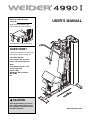
Weider WEEVSY2909 User manual
- Type
- User manual

M
odel No. WEEVSY2909.0
Serial No.
Write the serial number in the
space above for future reference.
USERʼS MANUAL
Serial Number Decal (under seat)
QUESTIONS?
If you have questions, or if there are
missing parts, please contact us:
Call: 08457 089 009
From Ireland: 053 92 36102
E-mail: www.iconsupport.eu
Write:
ICON Health & Fitness, Ltd.
c/o HI Group PLC
Express Way
Whitwood, West Yorkshire
WF10 5QJ
UK
CAUTION
Read all precautions and instruc-
tions in this manual before using
this equipment. Keep this manual
for future reference.
www.iconeurope.com

2
WARNING DECAL PLACEMENT
TABLE OF CONTENTS
WARNING DECAL PLACEMENT . . . . . . . . . . . . . . . . . . . . . . . . . . . . . . . . . . . . . . . . . . . . . . . . . . . . . . . . . . . . . 2
I
MPORTANT PRECAUTIONS . . . . . . . . . . . . . . . . . . . . . . . . . . . . . . . . . . . . . . . . . . . . . . . . . . . . . . . . . . . . . . . . 3
BEFORE YOU BEGIN . . . . . . . . . . . . . . . . . . . . . . . . . . . . . . . . . . . . . . . . . . . . . . . . . . . . . . . . . . . . . . . . . . . . . . 4
PART IDENTIFICATION CHART . . . . . . . . . . . . . . . . . . . . . . . . . . . . . . . . . . . . . . . . . . . . . . . . . . . . . . . . . . . . . .5
ASSEMBLY . . . . . . . . . . . . . . . . . . . . . . . . . . . . . . . . . . . . . . . . . . . . . . . . . . . . . . . . . . . . . . . . . . . . . . . . . . . . . . .6
ADJUSTMENT . . . . . . . . . . . . . . . . . . . . . . . . . . . . . . . . . . . . . . . . . . . . . . . . . . . . . . . . . . . . . . . . . . . . . . . . . . .23
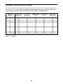
WEIGHT RESISTANCE CHART . . . . . . . . . . . . . . . . . . . . . . . . . . . . . . . . . . . . . . . . . . . . . . . . . . . . . . . . . . . . . .25
MAINTENANCE . . . . . . . . . . . . . . . . . . . . . . . . . . . . . . . . . . . . . . . . . . . . . . . . . . . . . . . . . . . . . . . . . . . . . . . . . .26
CABLE DIAGRAM . . . . . . . . . . . . . . . . . . . . . . . . . . . . . . . . . . . . . . . . . . . . . . . . . . . . . . . . . . . . . . . . . . . . . . . . .27
EXERCISE GUIDELINES . . . . . . . . . . . . . . . . . . . . . . . . . . . . . . . . . . . . . . . . . . . . . . . . . . . . . . . . . . . . . . . . . . .28
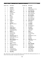
PART LIST . . . . . . . . . . . . . . . . . . . . . . . . . . . . . . . . . . . . . . . . . . . . . . . . . . . . . . . . . . . . . . . . . . . . . . . . . . . . . .29
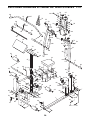
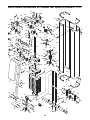
EXPLODED DRAWING . . . . . . . . . . . . . . . . . . . . . . . . . . . . . . . . . . . . . . . . . . . . . . . . . . . . . . . . . . . . . . . . . . . .30
ORDERING REPLACEMENT PARTS . . . . . . . . . . . . . . . . . . . . . . . . . . . . . . . . . . . . . . . . . . . . . . . . . .Back Cover
WEIDER is a registered trademark of ICON IP, Inc.
This drawing shows the location(s)
of the warning decal(s). If a decal
is missing or illegible, see the
front cover of this manual and
request a free replacement
decal. Apply the decal in the
location shown. Note: The
decal(s) may not be shown at
actual size.

3
IMPORTANT PRECAUTIONS
WARNING: To reduce the risk of serious injury, read all important precautions and
i
nstructions in this manual and all warnings on your weight system before using your weight sys-
tem. ICON assumes no responsibility for personal injury or property damage sustained by or
through the use of this product.
1. Before beginning any exercise program,
consult your physician. This is especially
important for persons over age 35 or per-
sons with pre-existing health problems.
2. It is the responsibility of the owner to ensure
that all users of the weight system are ade-
quately informed of all precautions.
3. The weight system is intended for home use
only. Do not use the weight system in a com-
mercial, rental, or institutional setting.
4. Use the weight system only on a level sur-
face. Cover the floor beneath the weight
system to protect the floor.
5. Inspect and properly tighten all parts regu-
larly. Replace any worn parts immediately.
6. Keep children under age 12 and pets away
from the weight system at all times.
7. The weight system should not be used by
persons weighing more than 300 lbs.
(136 kg).
8. Wear appropriate exercise clothes while
exercising; do not wear loose clothes that
could become caught on the weight system.
Always wear athletic shoes for foot protec-
tion.
9. Keep hands and feet away from moving
parts.
10. Make sure that the cables remain on the pul-
leys at all times. If the cables bind while you
are exercising, stop immediately and make
sure that the cables are on the pulleys.
11. Never release the arms, leg lever, lat bar,
rower bar, or ab handle while weights are
raised. The weights will fall with great force.
12. Always disconnect the lat bar and the rower
bar from the weight system when performing
an exercise that does not require them.
13. To prevent tipping, always sit on the seat or
stand on the foot plate while using the
weight system.
14. Over exercising may result in serious injury
or death. If you feel faint or if you experience
pain while exercising, stop immediately and
cool down.
15. Use the weight system only as described in
this manual.

4
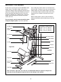
High Pulley
Station
Right Side
Left Side
Note: The terms “right side” and “left side” are determined relative to a person sitting on the
seat; they do not correspond to right and left on the drawings in the manual.
BEFORE YOU BEGIN
Thank you for selecting the versatile WEIDER
®
4990 I
w
eight system. The 4990 I weight system offers a
selection of weight stations designed to develop every
major muscle group of the body. Whether your goal is
to tone your body, build dramatic muscle size and
strength, or improve your cardiovascular system, the
weight system will help you to achieve the specific
results you want.
For your benefit, read this manual carefully before
using your weight system. If you have questions
after reading this manual, please see the front cover
o
f this manual. To help us assist you, note the product
model number and serial number before contacting
us. The model number and the location of the serial
number decal are shown on the front cover of this
manual.
Before reading further, please review the drawing
below and familiarize yourself with the parts that are
labeled.
Backrest
Lat Bar Rest
Ab Pulley Station
Lat Bar
Arm
Leg Lever
Low Pulley
Station
Curl Pad
Shroud
Ab Handle
Seat
Chain
Rower Bar
Lock Knob
Foot Plate
Weight Pin
ASSEMBLED DIMENSIONS:
Height: 6 ft. 8 in. (203 cm)
Width: 3 ft. 7 in. (110 cm)
Depth: 5 ft. 0 in. (153 cm)

5
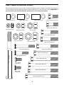
Refer to the drawings below and on page 6 to identify small parts used in assembly. The number in parentheses
b
y each drawing is the key number of the part, from the PART LIST near the end of this manual. IMPORTANT: If
you cannot find a part in the hardware kit, check to see if it has been preassembled.
PART IDENTIFICATION CHART
M10 x 52mm Bolt (67)
M10 x 50mm Bolt (58)
M10 x 32mm Bolt (59)
M10 x 25mm Screw (60)
M8 x 63mm Bolt (61)
M8 x 42mm Bolt (62)
M10 x 75mm Bolt (94)
1/2" x 7" Bolt (64)
M8 Locknut (69)
M10 Locknut (68)
1/2" Nut (84)
5/8" Locknut (75)
1/2" Locknut (70)
M8 x 16mm
Screw (63)
M8 x 20mm
Screw (65)
M10 x 65mm Bolt (37)
M10 x 85mm Bolt (95)
M10 x 95mm Bolt (66)
M10 x 103mm Bolt (57)
27mm Spacer (96)12mm Spacer (91) 22mm Spacer (97)
M10 x 93mm Bolt (99)

6
ASSEMBLY
1. Orient the Short Base (6) and the Long Base
(1) as shown.
Attach the Short Base (6) to the Long Base (1)
with two M10 x 103mm Bolts (57), four M10
Curved Washers (20), and two M10 Locknuts
(68).
1
1
6
68
20
20
20
20
57
57
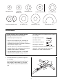
To make assembly easier, carefully read the
following information and instructions:
• Assembly requires two persons.
• Because of its weight and size, assemble the
weight system in the location where it will be
used. Make sure that there is enough clearance to
walk around the weight system.
• Place all parts in a cleared area and remove the
packing materials. Do not dispose of the packing
materials until assembly is completed.
• For help identifying small parts, use the PART
IDENTIFICATION CHART on pages 5 and 6.
• The following tools (not included) may be required
for assembly:
two adjustable wrenches
one rubber mallet
one standard screwdriver
one Phillips screwdriver
Assembly may be more convenient if you have a
socket set, a set of open-end or closed-end
wrenches, or a set of ratchet wrenches.
M10 Curved Washer (20)
S
mall M8
Washer (74)
M
6 Washer (79)
M
10 Washer (73)
5/8" Washer (71)
1/2" Washer (72)
13mm Washer (78)
2
26mm Washer (77)
Large M8 Washer (98)

7
2. Slide the two Weight Bumpers (25) onto the
Weight Guides (4), and insert the Weight
Guides into the Short Base (6).
A
ttach the Weight Guides (4) to the Short Base
(6) with two M10 x 25mm Screws (60) and two
M10 Washers (73).
2
4
6
60
25
73
73
25
3
4
15
15
Pin Hole
3. Orient the twelve Weights (15) so that the pin
holes are on the bottom of the Weights as
shown.
Slide the Weights (15) onto the Weight Guides
(4).

8
4. Orient the Top Weight Bushing (26) and the
Weight Selector (7) as shown. Slide the Top
Weight Bushing onto the Weight Selector, and
a
lign the hole in the Top Weight Bushing with
the highest hole in the Weight Selector.
Next, insert the Bushing Pin (28) into the Top
Weight Bushing (26) and the Weight Selector
(7).
Then, insert the Weight Selector (7) into the
twelve Weights (15).
Next, apply some of the included grease to the
indicated holes in the Top Weight (16).
Slide the Top Weight (16) onto the Weight
Guides (4), and press the Top Weight down
onto the Weight Selector (7).
Then, insert the Weight Pin (18) into one of the
Weights (15).
4
4
Grease
7
28
26
18
15
1
6

9
5. Orient the Upright (5) as shown.
Attach the Upright (5) to the Long Base (1) with
t
wo M10 x 103mm Bolts (57), four M10
Washers (73), and two M10 Locknuts (68); do
n
ot tighten the Locknuts yet.
5
5
68
73
73
73
73
1
57
6. Orient the Seat Frame (2) as shown.
Attach the Seat Frame (2) to the Upright (5)
with two M10 x 52mm Bolts (67), four M10
Washers (73), and two M10 Locknuts (68); do
not tighten the Locknuts yet.
6
5
67
2
67
73
73
73
73
68

10
7
. Orient the Leg (21) as shown.
Insert the indicated bracket on the Leg (21) into
the Seat Frame (2). Attach the Leg to the Seat
F
rame with an M10 x 93mm Bolt (99), two M10
Curved Washers (20), and an M10 Locknut
(
68); do not tighten the Locknut yet.
Next, attach the Leg (21) to the Long Base (1)
with two M10 x 103mm Bolts (57), four M10
Washers (73), and two M10 Locknuts (68); do
not tighten the Locknuts yet.
7
8. Apply grease to an M10 x 75mm Bolt (94).
Orient the Leg Lever (3) as shown.
Attach the Leg Lever (3) to the Leg (21) with the
M10 x 75mm Bolt (94), two M10 Washers (73),
and an M10 Locknut (68). Do not overtighten
the Locknut; the Leg Lever must pivot eas-
ily.
8
68
68
2
Bracket
1
73
73
20
20
21
99
68
73
73
94
21
3
9. Attach the Top Frame (8) to the Upright (5) with
two M10 x 103mm Bolts (57), four M10
Washers (73), and two M10 Locknuts (68); do
not tighten the Locknuts yet.
Then, attach the Top Frame (8) to the Weight
Guides (4) with two M10 x 25mm Screws (60)
and two M10 Washers (73).
See steps 5 through 9. Tighten all of the M10
Locknuts (68).
9
60
73
8
5
57
4
68
73
73
Grease
57

11
1
0. Apply grease to a 1/2" x 7" Bolt (64).
Orient the Arm Frame (9) as shown.
A
ttach the Arm Frame (9) to the Top Frame (8)
with the 1/2" x 7" Bolt (64), two 1/2" Washers
(
72), and a 1/2" Locknut (70). Do not over-
tighten the Locknut; the Arm Frame must
pivot easily.
10
8
9
64
72
72
70
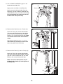
11. Apply grease to an M8 x 42mm Bolt (62).
Hold the Lock Rod (46) inside the bracket on
the Upright (5). Attach the Lock Rod with the
M8 x 42mm Bolt (62), two Small M8 Washers
(74), and an M8 Locknut (69). Do not over-
tighten the Locknut; the Lock Rod must
pivot easily.
Then, tighten the Lock Knob (45) onto the end
of the Lock Rod (46).
11
12. Apply grease to an M8 x 63mm Bolt (61).
Attach a U-bracket (22) to one side of the
Upright (5) with the M8 x 63mm Bolt (61), two
Small M8 Washers (74), and an M8 Locknut
(69). Do not overtighten the Locknut; the U-
bracket must pivot easily.
Attach the other U-bracket (22) to the
Upright (5) in the same way.
12
5
5
62
74
69
74
45
46
22
Grease
69
74
Grease
61
Grease
74
22

12
1
3. Identify the Left Arm (12), which is marked with
an “L” sticker, and orient it as shown.
Apply grease to the axle on the Left Arm (12).
Insert the Left Arm (12) into the Arm Frame (9).
A
ttach the Left Arm with a 5/8" Locknut (75) and
a 5/8" Washer (71). Do not overtighten the
Locknut; the Left Arm must pivot easily.
Then, press a 5/8" Domed Cap (56) onto the
5/8" Locknut (75).
Attach the Right Arm (13) in the same way.
13
12
9
13
56
75
71
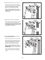
14. Slide a Large Foam Pad (48) onto the Left Arm
(12).
Insert a Handle (17) into the Left Arm (12).
Attach the Handle with an M10 x 25mm Screw
(60) and an M10 Washer (73).
Repeat this step for the Right Arm (13).
14
12
13
48
Grease
60
73
17

13
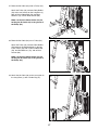
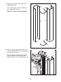
1
5. See the CABLE DIAGRAM on page 27 and
identify the Arm Cable (51).
Apply grease to an M10 x 32mm Bolt (59).
Attach one end of the Arm Cable (51) to the
R
ight Arm (13) with the M10 x 32mm Bolt (59),
an M10 Washer (73), and an M10 Locknut (68).
Do not overtighten the Locknut; the end of
the Arm Cable must pivot easily.
15
73
68
5
9
13
51
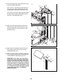
17. Route the Arm Cable (51) under a Pulley (42).
Attach the Pulley (42) and two Cable Guides
(52) to one end of the Offset Double U-bracket
(85) with an M10 x 50mm Bolt (58), two M10
Washers (73), and an M10 Locknut (68).
Make sure that the Cable Guides (52) are
holding the Arm Cable (51) in the groove of
the Pulley (42).
17
16. Route the Arm Cable (51) over a Pulley (42).
Attach the Pulley (42) and two Cable Guides
(52) to the right U-bracket (22) on the Upright
(5) with an M10 x 50mm Bolt (58), two M10
Washers (73), and an M10 Locknut (68). Make
sure that the Cable Guides are oriented as
shown.
See the inset drawing. Make sure that the
Cable Guides (52) are holding the Arm Cable
(51) in the groove of the Pulley (42).
16
42
42
51
52
52
58
85
73
52
51
73
58
5
52
22
52
52
51
42
Grease
68
73
68

14
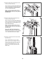
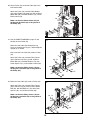
1
8. Route the Arm Cable (51) over a Pulley (42).
Attach the Pulley (42) and two Cable Guides
(52) to the left U-bracket (22) on the Upright (5)
w
ith an M10 x 50mm Bolt (58), two M10
Washers (73), and an M10 Locknut (68).
Make sure that the Cable Guides (52) are
holding the Arm Cable (51) in the groove of
the Pulley (42).
18
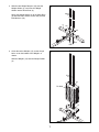
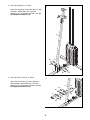
19. Apply grease to an M10 x 32mm Bolt (59).
Attach the end of the Arm Cable (51) to the Left
Arm (12) with the M10 x 32mm Bolt (59), an
M10 Washer (73), and an M10 Locknut (68). Do
not overtighten the Locknut; the end of the
Arm Cable must pivot easily.
19
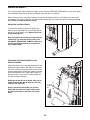
20. See the CABLE DIAGRAM on page 27 and
identify the High Cable (53).
Route the High Cable (53) over a Pulley (42).
Attach the Pulley (42) and two Pulley Covers
(36) to the front bracket on the Top Frame (8)
with an M10 x 50mm Bolt (58), two M10
Washers (73), and an M10 Locknut (68).
Make sure that the Pulley Covers (36) are
holding the High Cable (53) in the groove of
the Pulley (42).
Then, route the High Cable (53) through the
Arm Frame (9) and through the Upright (5) as
shown.
20
58
42
51
51
12
52
52
22
68
68
36
36
53
42
73
73
58
8
9
5
73
Grease
73
68
73
5
59

15
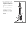
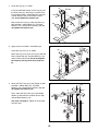
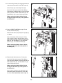
2
1. Route the High Cable (53) through the center
bracket on the Top Frame (8).
Attach a Pulley (42) and two Cable Guides (52)
t
o the center bracket on the Top Frame (8) with
an M10 x 52mm Bolt (67), two M10 Washers
(
73), and an M10 Locknut (68).
Make sure that the Cable Guides (52) are
holding the High Cable (53) in the groove of
the Pulley (42).
21
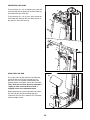
22. Route the High Cable (53) through the rear
bracket on the Top Frame (8).
Attach a Pulley (42) and two Cable Guides (52)
to the rear bracket on the Top Frame (8) with an
M10 x 50mm Bolt (58), two M10 Washers (73),
and an M10 Locknut (68).
Make sure that the Cable Guides (52) are
holding the High Cable (53) in the groove of
the Pulley (42).
Then, pull the High Cable (53) downward
between the center and rear brackets on the
Top Frame (8) so that there is slack in the High
Cable. The slack will be used in step 24.
22
23. Thread a 1/2" Nut (84) all of the way onto the
High Cable (53).
Place a 26mm Washer (77) and a 13mm
Washer (78) on top of the Weight Selector (7).
Tighten the High Cable (53) three quarters of
the way into the Weight Selector (7). Then,
tighten the 1/2" Nut (84) against the 13mm
Washer (78).
23
6
8
73
73
53
67
42
8
68
73
73
58
8
53
53
84
78
77
7
52
52
52
42
52

16
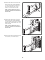
2
4. Locate the High Cable (53) hanging between the
center and rear brackets on the Top Frame (8).
Hold a Pulley (42) on the High Cable (53).
Attach the Pulley (42) and two Cable Guides
(
52) between the highest holes in the two Pulley
Plates (23) with an M10 x 50mm Bolt (58), two
M10 Washers (73), and an M10 Locknut (68).
Make sure that the Cable Guides (52) are
holding the High Cable (53) in the groove of
the Pulley (42).
24
25. See the CABLE DIAGRAM on page 27 and
identify the Ab Cable (93).
Route the Ab Cable (93) through the Upright (5)
as shown.
Next, route the Ab Cable (93) over a Pulley
(42). Attach the Pulley and two Pulley Covers
(36) inside the Upright (5) with an M10 x 85mm
Bolt (95), two M10 Washers (73), two 22mm
Spacers (97), and an M10 Locknut (68).
Make sure that the Pulley Covers (36) are
holding the Ab Cable (93) in the groove of
the Pulley (42).
25
26. Route the Ab Cable (93) over a Pulley (42).
Attach the Pulley (42) and two Cable Guides
(52) to the Offset Double U-bracket (85) with an
M10 x 50mm Bolt (58), two M10 Washers (73),
and an M10 Locknut (68).
Make sure that the Cable Guides (52) are
holding the Ab Cable (93) in the groove of
the Pulley (42).
Then, pull the Ab Cable (93) downward in the
indicated location so that there is slack in the
Ab Cable. The slack will be used in step 30.
26
8
5
3
52
52
5
95
36
42
73
73
73
93
68
7
3
68
23
58
52
93
85
73
68
23
36
42
97
97
73
58
42
Pull
52

17
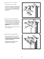
2
7. Route the Ab Cable (93) under a Pulley (42).
Attach the Pulley (42) and two Cable Guides
(52) to the rear bracket on the Long Base (1)
w
ith an M10 x 50mm Bolt (58), two M10
Washers (73), and an M10 Locknut (68).
Make sure that the Cable Guides (52) are
holding the Ab Cable (93) in the groove of
the Pulley (42).
27
28. Route the Ab Cable (93) over a Pulley (42).
Attach the Pulley (42) and two Cable Guides
(52) between the indicated holes in the two
Pulley Plates (23) with an M10 x 50mm Bolt
(58), two M10 Washers (73), and an M10
Locknut (68).
Make sure that the Cable Guides (52) are
holding the Ab Cable (93) in the groove of
the Pulley (42).
28
29. Attach the Ab Cable (93) to the rear eyelet on
the Long Base (1) with a Cable Clip (47).
29
42
93
58
1
1
58
73
73
42
52
52
68
93
52
73
23
52
93
47
73
68

18
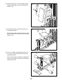
3
0. Hold a Pulley (42) on the Ab Cable (93) in the
indicated location.
Attach the Pulley (42) and two Cable Guides
(
52) to the Double U-bracket (24) with an M10 x
50mm Bolt (58), two M10 Washers (73), and an
M
10 Locknut (68).
Make sure that the Cable Guides (52) are
holding the Ab Cable (93) in the groove of
the Pulley (42).
68
73
24
42
93
52
5
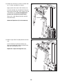
2
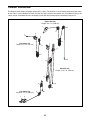
31. See the CABLE DIAGRAM on page 27 and
identify the Low Cable (54).
Route the Low Cable (54) through the Leg
Lever (3), through the Leg (21), and through the
Upright (5) as shown.
Next, route the Low Cable (54) under a Pulley
(42).
Attach the Pulley (42) and two Pulley Covers
(36) inside the Leg Lever (3) with an M10 x
65mm Bolt (37), two M10 Washers (73), two
12mm Spacers (91), and an M10 Locknut (68).
Make sure that the Pulley Covers (36) are
holding the Low Cable (54) in the groove of
the Pulley (42).
31
32. Route the Low Cable (54) under a Pulley (42).
Attach the Pulley (42) and two Pulley Covers
(36) inside the Leg (21) with an M10 x 95mm
Bolt (66), two M10 Washers (73), two 27mm
Spacers (96), and an M10 Locknut (68).
Make sure that the Pulley Covers (36) are
holding the Low Cable (54) in the groove of
the Pulley (42).
32
54
3
21
5
37
36
73
91
91
73
68
21
66
73
54
96
96
73
68
36
36
42
42
36
58
7
3
30

19
34. Route the Low Cable (54) over a Pulley (42).
Attach the Pulley (42) and two Cable Guides
(52) to the Double U-bracket (24) with an M10 x
50mm Bolt (58), two M10 Washers (73), and an
M10 Locknut (68).
Make sure that the Cable Guides (52) are
holding the Low Cable (54) in the groove of
the Pulley (42).
52
54
24
73
68
42
73
58
52
34
35. Attach the Low Cable (54) to the front eyelet on
the Long Base (1) with a Cable Clip (47).
35
1
54
47
33. Route the Low Cable (54) under a Pulley (42).
Attach the Pulley (42) and two Cable Guides
(
52) to the front bracket on the Long Base (1)
with an M10 x 50mm Bolt (58), two M10
W
ashers (73), and an M10 Locknut (68).
Make sure that the Cable Guides (52) are
holding the Low Cable (54) in the groove of
the Pulley (42).
33
1
58
73
73
4
2
54
6
8
52
5
2

20
37. Orient the Seat (10) so that the wide end is in
the indicated position.
Attach the Seat (10) to the Seat Frame (2) with
four M8 x 16mm Screws (63) and four Small M8
Washers (74).
37
10
63
74
Wide
End
2
63
74
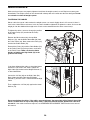
38. Insert a Pad Tube (19) through the bracket on
the Leg (21). Slide two Small Foam Pads (39)
onto the Pad Tube.
Next, insert the other Pad Tube (19) through the
Leg Lever (3). Slide two Small Foam Pads (39)
onto the Pad Tube.
38
39
39
19
3
21
39
39
19
3
6. Attach the Backrest (11) to the Upright (5) with
two M8 x 42mm Bolts (62) and two Small M8
Washers (74).
36
11
5
6
2
74
Page is loading ...
Page is loading ...
Page is loading ...
Page is loading ...
Page is loading ...
Page is loading ...
Page is loading ...
Page is loading ...
Page is loading ...
Page is loading ...
Page is loading ...
Page is loading ...
-
 1
1
-
 2
2
-
 3
3
-
 4
4
-
 5
5
-
 6
6
-
 7
7
-
 8
8
-
 9
9
-
 10
10
-
 11
11
-
 12
12
-
 13
13
-
 14
14
-
 15
15
-
 16
16
-
 17
17
-
 18
18
-
 19
19
-
 20
20
-
 21
21
-
 22
22
-
 23
23
-
 24
24
-
 25
25
-
 26
26
-
 27
27
-
 28
28
-
 29
29
-
 30
30
-
 31
31
-
 32
32


Weider WEEVSY2909 User manual
- Type
- User manual
Ask a question and I''ll find the answer in the document
Finding information in a document is now easier with AI
Related papers
-
Weider WEEVSY1909 User manual
-
-
-
-
-
-
-
Sears 831154030 User manual
-
WeiderPro PRO 6900 SYSTEM 14922 User manual
-
Other documents
-
-
-
Gold's Gym XRS 50 User manual
-
Weslo Gym 2500 User manual
-
-
NordicTrack 360 W/freemotion User manual
-
-
Epic 700 Vx User manual
-
FreeMotion 1020 SY User manual
-