Page is loading ...

SCXI
™
SCXI-1127/1128
User Manual
SCXI-1127/1128 User Manual
December 2000 Edition
Part Number 322149B-01

Worldwide Technical Support and Product Information
ni.com
National Instruments Corporate Headquarters
11500 North Mopac Expressway Austin, Texas 78759-3504 USA Tel: 512 794 0100
Worldwide Offices
Australia 03 9879 5166, Austria 0662 45 79 90 0, Belgium 02 757 00 20, Brazil 011 284 5011,
Canada (Calgary) 403 274 9391, Canada (Ontario) 905 785 0085, Canada (Québec) 514 694 8521,
China 0755 3904939, Denmark 45 76 26 00, Finland 09 725 725 11, France 01 48 14 24 24,
Germany 089 741 31 30, Greece 30 1 42 96 427, Hong Kong 2645 3186, India 91805275406,
Israel 03 6120092, Italy 02 413091, Japan 03 5472 2970, Korea 02 596 7456, Mexico (D.F.) 5 280 7625,
Mexico (Monterrey) 8 357 7695, Netherlands 0348 433466, New Zealand 09 914 0488, Norway 32 27 73 00,
Poland 0 22 528 94 06, Portugal 351 1 726 9011, Singapore 2265886, Spain 91 640 0085,
Sweden 08 587 895 00, Switzerland 056 200 51 51, Taiwan 02 2528 7227, United Kingdom 01635 523545
For further support information, see the Technical Support Resources appendix. To comment on the
documentation, send e-mail to [email protected]
© Copyright 1999, 2000 National Instruments Corporation. All rights reserved.

Important Information
Warranty
The SCXI-1127 and SCXI-1128 are warranted against defects in materials and workmanship for a period of one year from the date
of shipment, as evidenced by receipts or other documentation. National Instruments will, at its option, repair or replace equipment
that proves to be defective during the warranty period. This warranty includes parts and labor.
The media on which you receive National Instruments software are warranted not to fail to execute programming instructions,
due to defects in materials and workmanship, for a period of 90 days from date of shipment, as evidenced by receipts or other
documentation. National Instruments will, at its option, repair or replace software media that do not execute programming
instructions if National Instruments receives notice of such defects during the warranty period. National Instruments does not
warrant that the operation of the software shall be uninterrupted or error free.
A Return Material Authorization (RMA) number must be obtained from the factory and clearly marked on the outside of
the package before any equipment will be accepted for warranty work. National Instruments will pay the shipping costs of
returning to the owner parts which are covered by warranty.
National Instruments believes that the information in this document is accurate. The document has been carefully reviewed
for technical accuracy. In the event that technical or typographical errors exist, National Instruments reserves the right to
make changes to subsequent editions of this document without prior notice to holders of this edition. The reader should consult
National Instruments if errors are suspected. In no event shall National Instruments be liable for any damages arising out of
or related to this document or the information contained in it.
E
XCEPT
AS
SPECIFIED
HEREIN
, N
ATIONAL
I
NSTRUMENTS
MAKES
NO
WARRANTIES
,
EXPRESS
OR
IMPLIED
,
AND
SPECIFICALLY
DISCLAIMS
ANY
WARRANTY
OF
MERCHANTABILITY
OR
FITNESS
FOR
A
PARTICULAR
PURPOSE
. C
USTOMER
’
S
RIGHT
TO
RECOVER
DAMAGES
CAUSED
BY
FAULT
OR
NEGLIGENCE
ON
THE
PART
OF
N
ATIONAL
I
NSTRUMENTS
SHALL
BE
LIMITED
TO
THE
AMOUNT
THERETOFORE
PAID
BY
THE
CUSTOMER
. N
ATIONAL
I
NSTRUMENTS
WILL
NOT
BE
LIABLE
FOR
DAMAGES
RESULTING
FROM
LOSS
OF
DATA
,
PROFITS
,
USE
OF
PRODUCTS
,
OR
INCIDENTAL
OR
CONSEQUENTIAL
DAMAGES
,
EVEN
IF
ADVISED
OF
THE
POSSIBILITY
THEREOF
. This limitation of the liability of National Instruments will
apply regardless of the form of action, whether in contract or tort, including negligence. Any action against National Instruments
must be brought within one year after the cause of action accrues. National Instruments shall not be liable for any delay in
performance due to causes beyond its reasonable control. The warranty provided herein does not cover damages, defects,
malfunctions, or service failures caused by owner’s failure to follow the National Instruments installation, operation, or
maintenance instructions; owner’s modification of the product; owner’s abuse, misuse, or negligent acts; and power failure or
surges, fire, flood, accident, actions of third parties, or other events outside reasonable control.
Copyright
Under the copyright laws, this publication may not be reproduced or transmitted in any form, electronic or mechanical, including
photocopying, recording, storing in an information retrieval system, or translating, in whole or in part, without the prior written
consent of National Instruments Corporation.
Trademarks
CVI™, IVI™, LabVIEW™, Measurement Studio™, National Instruments™, ni.com™, NI-VISA™, PXI™, SCXI™, and
VirtualBench™ are trademarks of National Instruments Corporation.
Product and company names mentioned herein are trademarks or trade names of their respective companies.
WARNING REGARDING USE OF NATIONAL INSTRUMENTS PRODUCTS
(1) NATIONAL INSTRUMENTS PRODUCTS ARE NOT DESIGNED WITH COMPONENTS AND TESTING FOR A LEVEL
OF RELIABILITY SUITABLE FOR USE IN OR IN CONNECTION WITH SURGICAL IMPLANTS OR AS CRITICAL
COMPONENTS IN ANY LIFE SUPPORT SYSTEMS WHOSE FAILURE TO PERFORM CAN REASONABLY BE
EXPECTED TO CAUSE SIGNIFICANT INJURY TO A HUMAN.
(2) IN ANY APPLICATION, INCLUDING THE ABOVE, RELIABILITY OF OPERATION OF THE SOFTWARE PRODUCTS
CAN BE IMPAIRED BY ADVERSE FACTORS, INCLUDING BUT NOT LIMITED TO FLUCTUATIONS IN ELECTRICAL
POWER SUPPLY, COMPUTER HARDWARE MALFUNCTIONS, COMPUTER OPERATING SYSTEM SOFTWARE
FITNESS, FITNESS OF COMPILERS AND DEVELOPMENT SOFTWARE USED TO DEVELOP AN APPLICATION,
INSTALLATION ERRORS, SOFTWARE AND HARDWARE COMPATIBILITY PROBLEMS, MALFUNCTIONS OR
FAILURES OF ELECTRONIC MONITORING OR CONTROL DEVICES, TRANSIENT FAILURES OF ELECTRONIC
SYSTEMS (HARDWARE AND/OR SOFTWARE), UNANTICIPATED USES OR MISUSES, OR ERRORS ON THE PART OF
THE USER OR APPLICATIONS DESIGNER (ADVERSE FACTORS SUCH AS THESE ARE HEREAFTER
COLLECTIVELY TERMED “SYSTEM FAILURES”). ANY APPLICATION WHERE A SYSTEM FAILURE WOULD
CREATE A RISK OF HARM TO PROPERTY OR PERSONS (INCLUDING THE RISK OF BODILY INJURY AND DEATH)
SHOULD NOT BE RELIANT SOLELY UPON ONE FORM OF ELECTRONIC SYSTEM DUE TO THE RISK OF SYSTEM
FAILURE. TO AVOID DAMAGE, INJURY, OR DEATH, THE USER OR APPLICATION DESIGNER MUST TAKE
REASONABLY PRUDENT STEPS TO PROTECT AGAINST SYSTEM FAILURES, INCLUDING BUT NOT LIMITED TO
BACK-UP OR SHUT DOWN MECHANISMS. BECAUSE EACH END-USER SYSTEM IS CUSTOMIZED AND DIFFERS
FROM NATIONAL INSTRUMENTS' TESTING PLATFORMS AND BECAUSE A USER OR APPLICATION DESIGNER
MAY USE NATIONAL INSTRUMENTS PRODUCTS IN COMBINATION WITH OTHER PRODUCTS IN A MANNER NOT
EVALUATED OR CONTEMPLATED BY NATIONAL INSTRUMENTS, THE USER OR APPLICATION DESIGNER IS
ULTIMATELY RESPONSIBLE FOR VERIFYING AND VALIDATING THE SUITABILITY OF NATIONAL
INSTRUMENTS PRODUCTS WHENEVER NATIONAL INSTRUMENTS PRODUCTS ARE INCORPORATED IN A
SYSTEM OR APPLICATION, INCLUDING, WITHOUT LIMITATION, THE APPROPRIATE DESIGN, PROCESS AND
SAFETY LEVEL OF SUCH SYSTEM OR APPLICATION.

Compliance
FCC/Canada Radio Frequency Interference Compliance*
Determining FCC Class
The Federal Communications Commission (FCC) has rules to protect wireless communications from interference.
The FCC places digital electronics into two classes. These classes are known as Class A (for use in industrial-
commercial locations only) or Class B (for use in residential or commercial locations). Depending on where it is
operated, this product could be subject to restrictions in the FCC rules. (In Canada, the Department of
Communications (DOC), of Industry Canada, regulates wireless interference in much the same way.)
Digital electronics emit weak signals during normal operation that can affect radio, television, or other wireless
products. By examining the product you purchased, you can determine the FCC Class and therefore which of the two
FCC/DOC Warnings apply in the following sections. (Some products may not be labeled at all for FCC; if so, the
reader should then assume these are Class A devices.)
FCC Class A products only display a simple warning statement of one paragraph in length regarding interference and
undesired operation. Most of our products are FCC Class A. The FCC rules have restrictions regarding the locations
where FCC Class A products can be operated.
FCC Class B products display either a FCC ID code, starting with the letters EXN,
or the FCC Class B compliance mark that appears as shown here on the right.
Consult the FCC web site
http://www.fcc.gov
for more information.
FCC/DOC Warnings
This equipment generates and uses radio frequency energy and, if not installed and used in strict accordance with the
instructions in this manual and the CE Mark Declaration of Conformity**, may cause interference to radio and
television reception. Classification requirements are the same for the Federal Communications Commission (FCC)
and the Canadian Department of Communications (DOC).
Changes or modifications not expressly approved by National Instruments could void the user’s authority to operate
the equipment under the FCC Rules.
Class A
Federal Communications Commission
This equipment has been tested and found to comply with the limits for a Class A digital device, pursuant to part 15
of the FCC Rules. These limits are designed to provide reasonable protection against harmful interference when the
equipment is operated in a commercial environment. This equipment generates, uses, and can radiate radio frequency
energy and, if not installed and used in accordance with the instruction manual, may cause harmful interference to
radio communications. Operation of this equipment in a residential area is likely to cause harmful interference in
which case the user will be required to correct the interference at his own expense.
Canadian Department of Communications
This Class A digital apparatus meets all requirements of the Canadian Interference-Causing Equipment Regulations.
Cet appareil numérique de la classe A respecte toutes les exigences du Règlement sur le matériel brouilleur du
Canada.
Class B
Federal Communications Commission
This equipment has been tested and found to comply with the limits for a Class B digital device, pursuant to part 15
of the FCC Rules. These limits are designed to provide reasonable protection against harmful interference in a
residential installation. This equipment generates, uses and can radiate radio frequency energy and, if not installed
and used in accordance with the instructions, may cause harmful interference to radio communications. However,
there is no guarantee that interference will not occur in a particular installation. If this equipment does cause harmful
interference to radio or television reception, which can be determined by turning the equipment off and on, the user
is encouraged to try to correct the interference by one or more of the following measures:
• Reorient or relocate the receiving antenna.
• Increase the separation between the equipment and receiver.

• Connect the equipment into an outlet on a circuit different from that to which the receiver is connected.
• Consult the dealer or an experienced radio/TV technician for help.
Canadian Department of Communications
This Class B digital apparatus meets all requirements of the Canadian Interference-Causing Equipment Regulations.
Cet appareil numérique de la classe B respecte toutes les exigences du Règlement sur le matériel brouilleur du
Canada.
European Union - Compliance to EEC Directives
Readers in the EU/EEC/EEA must refer to the Manufacturer's Declaration of Conformity (DoC) for information**
pertaining to the CE Mark compliance scheme. The Manufacturer includes a DoC for most every hardware product
except for those bought for OEMs, if also available from an original manufacturer that also markets in the EU, or
where compliance is not required as for electrically benign apparatus or cables.
* Certain exemptions may apply in the USA, see FCC Rules §15.103 Exempted devices, and §15.105(c).
Also available in sections of CFR 47.
** The CE Mark Declaration of Conformity will contain important supplementary information and instructions
for the user or installer.

Conventions
The following conventions are used in this manual:
<> Angle brackets that contain numbers separated by an ellipsis represent a
range of values associated with a bit or signal name—for example,
DBIO<3..0>.
» The » symbol leads you through nested menu items and dialog box options
to a final action. The sequence File»Page Setup»Options directs you to
pull down the File menu, select the Page Setup item, and select Options
from the last dialog box.
This icon denotes a note, which alerts you to important information.
This icon denotes a caution, which advises you of precautions to take to
avoid injury, data loss, or a system crash.
bold Bold text denotes items that you must select or click on in the software,
such as menu items and dialog box options. Bold text also denotes
parameter names.
italic Italic text denotes variables, emphasis, a cross reference, or an introduction
to a key concept. This font also denotes text that is a placeholder for a word
or value that you must supply.
monospace
Text in this font denotes text or characters that you should enter from the
keyboard, sections of code, programming examples, and syntax examples.
This font is also used for the proper names of disk drives, paths, directories,
programs, subprograms, subroutines, device names, functions, operations,
variables, filenames and extensions, and code excerpts.

© National Instruments Corporation vii SCXI-1127/1128 User Manual
Contents
Chapter 1
Installing and Configuring the SCXI-1127/1128
Installing the Software ...................................................................................................1-2
Installing the Hardware..................................................................................................1-3
Installing the SCXI-1127/1128 Module into the SCXI Chassis......................1-4
Connecting the SCXI-1127/1128 to the DMM in a Single-Chassis System...1-5
Single 4-Slot Chassis Configuration .................................................1-6
Single 12-Slot Chassis Configuration ...............................................1-8
Connecting the SCXI-1127/1128 to the DMM in a Multichassis System ......1-10
4-Slot and 4-Slot Multichassis Configuration...................................1-10
4-Slot and 12-Slot Multichassis Configuration.................................1-12
12-Slot and 12-Slot Multichassis Configuration...............................1-14
Connecting the SCXI-1127/1128 to the DMM in a PXI-1010 Chassis ..........1-16
DMM in PXI Slots 1 through 7 Configuration .................................1-16
DMM in PXI Slot 8 Configuration ...................................................1-17
Connecting the SCXI-1127/1128 to the DMM in the PXI-1011 Chassis .......1-17
DMM in PXI Slots 1 through 3 Configuration .................................1-18
DMM in PXI Slot 4 Configuration ...................................................1-18
Accessing the SCXI-1127/1128 through Other SCXI Modules Using
a DAQ Device ..............................................................................................1-18
Using a DAQ Device on a PXI-1010 Chassis .................................................1-20
Using a DAQ Device on a PXI-1011 Chassis .................................................1-20
Connecting the SCXI-1127/1128 to an External DMM..................................1-20
Configuring and Self-Test .............................................................................................1-22
Auto-Detecting Modules .................................................................................1-22
Manually Adding Modules..............................................................................1-23
Safety Information .........................................................................................................1-24
Chapter 2
Using the SCXI-1127/1128
Operating as a Multiplexer/Scanner ..............................................................................2-1
2-Wire Channel Scanning Configuration ........................................................2-3
1-Wire Channel Scanning Configuration ........................................................2-5
4-Wire Channel Scanning Configuration ........................................................2-6
4-Wire versus 2-Wire Resistance Measurement .............................................2-9
Mixed Mode Configuration.............................................................................2-10
Hardware-Timed and Software Scanning .......................................................2-11
Hardware-Timed Scanning ...............................................................2-12

Contents
SCXI-1127/1128 User Manual viii ni.com
Hardware-Timed Scanning Using a DMM ........................ 2-14
Hardware-Timed Scanning Using External Instruments ... 2-14
Synchronous Scanning ....................................................... 2-14
Handshaking Scanning....................................................... 2-15
Software Scanning............................................................................ 2-17
Making Temperature Measurements .............................................................. 2-17
Making Thermocouple Measurements ............................................. 2-17
Making RTD Measurements ............................................................ 2-19
Making Thermistor Measurements................................................... 2-19
Operating as a Matrix .................................................................................................... 2-20
32 × 1 Matrix Configuration ........................................................................... 2-20
4 × 8 Matrix Configuration ............................................................................. 2-21
Matrix Expansion............................................................................................ 2-24
Independent Mode ......................................................................................................... 2-29
Appendix A
Specifications
Appendix B
Accessories
Appendix C
Customizing Your Module
Appendix D
SCXI-1127/1128 Front Connector
Appendix E
Common Questions
Appendix F
Technical Support Resources

Contents
© National Instruments Corporation ix SCXI-1127/1128 User Manual
Glossary
Index
Figures
Figure 1-1. Installing the SCXI-1127/1128 into an SCXI Chassis ..........................1-4
Figure 1-2. 4-Slot Single-Chassis Installation .........................................................1-6
Figure 1-3. 4-Slot Configuration Parts Locator Diagram ........................................1-7
Figure 1-4. 12-Slot Single-Chassis Installation .......................................................1-8
Figure 1-5. 12-Slot Configuration Parts Locator Diagram ......................................1-9
Figure 1-6. 4-Slot to 4-Slot Multichassis Configuration Parts Locator
Diagram .................................................................................................1-11
Figure 1-7. 4-Slot to 12-Slot Multichassis Configuration Parts Locator
Diagram .................................................................................................1-13
Figure 1-8. 12-Slot to 12-Slot Multichassis Configuration Parts Locator
Diagram .................................................................................................1-15
Figure 1-9. Installing the SCXI-1127/1128 with Two DAQ Devices .....................1-19
Figure 2-1. SCXI-1331 Signal Connections ............................................................2-2
Figure 2-2. 2-Wire Block Diagram ..........................................................................2-3
Figure 2-3. 2-Wire Wiring Diagram ........................................................................2-4
Figure 2-4. 1-Wire Block Diagram ..........................................................................2-5
Figure 2-5. 1-Wire Wiring Diagram ........................................................................2-6
Figure 2-6. 4-Wire Block Diagram ..........................................................................2-7
Figure 2-7. 4-Wire Wiring Diagram ........................................................................2-8
Figure 2-8. Signal Connections for a 2-Wire Resistance Measurement ..................2-9
Figure 2-9. Signal Connections for a 4-Wire Resistance Measurement ..................2-10
Figure 2-10. Mixed Mode Scanning with an SCXI-1331 ..........................................2-11
Figure 2-11. Hardware Scanning Flowchart ..............................................................2-13
Figure 2-12. Cabling a DMM and Using the TRIG0 to Bus
the VMC/EXT_TRIG_IN to Non-Cabled Modules..............................2-14
Figure 2-13. Cabling an External DMM ....................................................................2-15
Figure 2-14. Daisy-Chained for Handshaking ...........................................................2-16
Figure 2-15. Connecting an External DMM to an SCXI-1127/1128
in an SCXI-2000 Series Chassis............................................................2-16
Figure 2-16. Temperature Measurement Wiring Diagram ........................................2-18
Figure 2-17. 2 × 4, 1-Wire Matrix Configuration ......................................................2-20
Figure 2-18. 1 × 32 Matrix Wiring Diagram..............................................................2-21
Figure 2-19. SCXI-1332 Terminal Block ..................................................................2-22
Figure 2-20. SCXI-1332 Connected to an SCXI-1127 ..............................................2-23
Figure 2-21. SCXI-1332 Connected to an SCXI-1127/1128 Schematic ...................2-24
Figure 2-22. 8 × 8 Matrix Parts Locator Diagram .....................................................2-25
Figure 2-23. 8 × 8 Matrix Schematic .........................................................................2-26

Contents
SCXI-1127/1128 User Manual x ni.com
Figure 2-24. 8 × 16 Matrix Parts Locator Diagram ................................................... 2-27
Figure 2-25. 8 × 16 Matrix Schematic....................................................................... 2-28
Figure 2-26. SCXI-1127/1128 Relay Configuration ................................................. 2-30
Figure C-1. Removing the SCXI Module Cover...................................................... C-1
Figure C-2. Bent and Trimmed Resistor .................................................................. C-2
Figure D-1. SCXI-1127/1128 Front Connector Pin Assignments
for 2-Wire Mode ................................................................................... D-2
Figure D-2. SCXI-1127/1128 Front Connector Pin Assignments
for 1-Wire Mode ................................................................................... D-3
Figure D-3. SCXI-1127/1128 Front Connector Pin Assignments
for 4-Wire Mode ................................................................................... D-4
Figure D-4. SCXI-1127/1128 Front Connector Pin Assignments to Create
an 4 × 8 Matrix...................................................................................... D-5
Tables
Table 1-1. SCXI-1127/1128 Configurations .......................................................... 1-1
Table D-1. Front Connector Signal Description ..................................................... D-6

© National Instruments Corporation 1-1 SCXI-1127/1128 User Manual
1
Installing and Configuring the
SCXI-1127/1128
The SCXI-1127 and SCXI-1228 modules are high-voltage
multiplexer/matrix modules. The SCXI-1127 is a high-density armature
relay module. The SCXI-1128 is a high-density solid-state relay module.
Both modules provide a 1 × 32, 2-wire multiplexer and several switch
matrix configurations on an SCXI platform. The SCXI-1127/1128 can also
operate as two 1 × 16 or four 1 × 8, 2-wire multiplexers (in independent
mode) allowing a single module to handle several multiplexing needs.
Through software-configurable switches, the module can also operate as a
1-wire 1 × 64 multiplexer, enabling you to make a large number of common
referenced measurements. It can also operate as a 1 × 64, 4-wire
multiplexer to make resistive measurements such as those needed for
thermistors and RTDs. With the use of special terminal blocks, the
SCXI-1127/1128 can become a 4 × 8 or 1 × 32, 2-wire matrix. A complete
list of possible configurations is given in Table 1-1.
To handle large channel counts, you can expand the size of the multiplexer
with additional SCXI-1127/1128 modules. These modules support the
analog bus through a special adapter, the high-voltage analog bus (HVAB)
backplane adapter in the SCXI-1357/1358 kit, at the rear of the module.
This adapter allows you to expand the HVAB without complicated wiring.
For example, you can connect two SCXI-1127/1128 modules using the
HVAB-backplane adapter to create a 1 × 64, 2-wire multiplexer.
Table 1-1.
SCXI-1127/1128 Configurations
Scanning
Configuration
Multiplexer Matrix
1-wire 1 × 64 N/A
2-wire 1 × 32 4 × 8 (also 2 × 16, 1 × 32)
4-wire 1 × 16 N/A

Chapter 1 Installing and Configuring the SCXI-1127/1128
SCXI-1127/1128 User Manual 1-2 ni.com
In a matrix configuration, you can expand the columns of the matrix using
the HVAB-backplane adapter. For example, you can connect two
SCXI-1127/1128 modules via the HVAB-backplane adapter to create a
4 × 16 matrix. You can also expand the rows and columns of a matrix
through the front connector of the SCXI-1127/1128 using the SCXI-1332
and matrix expansion cables. Refer to Chapter 2, Matrix Expansion, for
further information on matrix expansion.
The SCXI-1127/1128 is designed to work well at both low and high
voltages. For low-voltage measurements such as those taken with
thermocouples, the SCXI-1127/1128 uses relays with very low thermal
offset to ensure accurate measurements. At high voltages, the SCXI-1127
can handle signals up to 250 V
rms
at a 200 mA load and 30 VDC at a 1 A
load. The SCXI-1128 can handle signals up to 250 V
rms
at a 0.8 mA load
and 30 VDC at a 10 mA load. The SCXI-1127/1128 complies with the CE
low-voltage directive for an installation category II environment. Refer to
Appendix A, Specifications, for detailed specifications of the
SCXI-1127/1128.
The following section explains how to install the software required to
use the SCXI-1127/1128, including installing the latest version of
NI-SWITCH. After installing the software, install the SCXI-1127/1128
hardware and its accessories, then configure and test the SCXI-1127/1128.
Installing the Software
You can control the SCXI-1127/1128 programmatically in an application
development environment (ADE) using NI-SWITCH. The supported
ADEs include LabVIEW, Measurement Studio, Visual Basic, and C or
C++ environments. To install software for the SCXI-1129, complete the
following:
1. Insert your NI-SWITCH software CD into your CD-ROM drive.
2. Click the Install NI-SWITCH option from the installation window
that appears automatically.
Note
If the installation window does not appear, double-click the My Computer icon on
your PC desktop. Find the CD drive, and double-click it. In the CD directory, double-click
install.exe
.

Chapter 1 Installing and Configuring the SCXI-1127/1128
© National Instruments Corporation 1-3 SCXI-1127/1128 User Manual
The NI-SWITCH and NI-DMM version 1.5 installation window offers
three choices:
• Install NI-DMM—Choose this selection if you want to install
only the software for the DMM.
• Install NI-SWITCH—Choose this selection if you want to install
only the software for the switches.
• Install NI-SWITCH and NI-DMM—Choose this selection if
you want to install the software for both the DMM and the
switches.
3. To install the instrument driver, VirtualBench, and application
development examples, choose Programmatic and Interactive
Support. To install only the instrument driver files for VirtualBench,
choose Interactive Support Only.
Note
The Interactive Support Only choice will not allow you to program the instrument
with any programming languages.
4. When installing NI-SWITCH, notice the Development
Environments panel.
• If you click the Advanced button on this panel, you can custom
install National Instruments drivers such as NI-DAQ, NI-IVI, and
NI-VISA.
• If you do not want to install certain drivers, click Advanced and
uncheck the driver(s) you do not want installed.
If a driver is already unchecked, your computer has the same driver or
a newer version of the driver already installed.
Note
If a newer version of a driver is present on your PC, the installer will not overwrite
the driver.
5. After completing the installation, turn off your computer.
Installing the Hardware
The following section describes how to install your SCXI-1127/1128 for
use with SCXI chassis, National Instruments DAQ devices, and National
Instruments DMMs.

Chapter 1 Installing and Configuring the SCXI-1127/1128
SCXI-1127/1128 User Manual 1-4 ni.com
Installing the SCXI-1127/1128 Module into the SCXI Chassis
You need the following items to complete the installation:
• SCXI-1127/1128
• SCXI chassis
• 1/8 in. flathead screwdriver
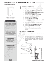
Figure 1-1.
Installing the SCXI-1127/1128 into an SCXI Chassis
Follow these steps to install your SCXI-1127/1128 module into the SCXI
chassis while referring to Figure 1-1.
1. Turn off the computer that contains the DAQ/DMM device or
disconnect it from your SCXI chassis.
2. Turn off the SCXI chassis. Do not insert the SCXI-1127/1128 module
into a chassis that is turned on.
3. Insert the SCXI-1127/1128 module into the rightmost slot. Gently
guide the module into the module guides and push it to the back of the
slot until the connectors make good contact. The module must be
firmly engaged; however do not force the module into place.
1 AB0+
2 AB0–
3 NI 4060 for PCI
4 AB2+
5AB2–
6 HV8-BAN4
7SH9MD-9MD
8 2-Slot HVAB-Backplane Adapter
9 SCXI Chassis
10 SCXI-1127/1128 Module
8
2
3
4
5
6
7
9
10
1

Chapter 1 Installing and Configuring the SCXI-1127/1128
© National Instruments Corporation 1-5 SCXI-1127/1128 User Manual
Note
When installing the SCXI-1127/1128 module in an SCXI chassis, the rightmost slot
(when the chassis is viewed from the front) must be filled first, then fill the slot to the left
with the next SCXI-1127/1128. Other SCXI modules can be loaded from left to right.
4. Insert any other SCXI modules into the remaining slots in the same
manner as described in step 3.
5. Secure all the SCXI-1127/1128 modules to the SCXI chassis using
both thumbscrews.
To finish installing your SCXI-1127/1128, follow one of the procedures in
the appropriate section that follows.
Connecting the SCXI-1127/1128 to the DMM in a Single-Chassis System
You need the following items for this installation:
• SCXI-1000/1000DC/1001 chassis with the SCXI-1127/1128 modules
installed
• SCXI-1357 (4-slot)/1358 (12-slot) kit
– 1-slot, 2-slot, and/or 8-slot HVAB-backplane adapter
– HV8-to-BAN4 cable
– SH9MD-9MD cable
– Two or three 8-position high-voltage plugs
• DMM
• 1/8 in. flathead screwdriver
Consult your SCXI chassis documentation and DMM documentation for
additional instructions and warnings. Your SCXI-1127/1128 modules and
any other SCXI modules should already be installed in the chassis
according to their installation instructions. Before you proceed with your
connections, make sure you turn off your SCXI chassis.

Chapter 1 Installing and Configuring the SCXI-1127/1128
SCXI-1127/1128 User Manual 1-6 ni.com
Single 4-Slot Chassis Configuration
Refer to Figures 1-2 and 1-3 to make connections in the single 4-slot
chassis configuration.
Figure 1-2.
4-Slot Single-Chassis Installation
1 SCXI-1127/1128 Module
2 4-Slot SCXI Chassis
3 2-Slot HVAB-Backplane
Adapter
4 1-Slot HVAB-Backplane
Adapter
5 8-Position HVAB Plug
6NI 4060 for PCI
7 SH9MD-9MD Cable
8 HV8-BAN4 Cable
7
8
1
3
4
5
2
6

Chapter 1 Installing and Configuring the SCXI-1127/1128
© National Instruments Corporation 1-7 SCXI-1127/1128 User Manual
Figure 1-3.
4-Slot Configuration Parts Locator Diagram
1. Install the 2-slot HVAB-backplane adapter behind slots 3 and 4.
2. Install additional 1-slot HVAB-backplane adapters behind slots 1
and 2 if needed.
3. Install the 8-position HVAB plugs to connect the HVAB-backplane
adapters as needed.
4. Connect the HV8-BAN4 cable from the DMM to the HVAB connector
behind slot 4.
5. Connect the SH9MD-9MD cable from the DMM to the AUX IN
connector.
6. You can install any additional SCXI-1127/1128 modules in any slot
that has an HVAB-backplane adapter behind it.
Note
An SCXI-1127/1128 is required in slot 4 to establish communication with the
chassis. If slot 4 is empty, the system will not operate. It is this module that you must
specify in Measurement & Automation Explorer (MAX) as the module cabled to the
DMM.
1 2-Slot HVAB-Backplane
Adapter
2 8-Position HVAB Plug
3 1-Slot HVAB-Backplane
Adapter
4 HV8-BAN4 Cable
5 NI 4060 for PCI
6 SH9MD-9MD Cable
7 4-Slot SCXI Chassis
AB0+
AB0–
AB2+
AB2–
5
6
7
2
4
1
3

Chapter 1 Installing and Configuring the SCXI-1127/1128
SCXI-1127/1128 User Manual 1-8 ni.com
Single 12-Slot Chassis Configuration
Refer to Figures 1-4 and 1-5 to make connections in the single 12-slot
chassis configuration.
Figure 1-4.
12-Slot Single-Chassis Installation
1 SCXI-1127/1128 Module
2 12-Slot SCXI Chassis
3 2-Slot HVAB-Backplane
Adapter
4 1-Slot HVAB-Backplane
Adapter
5 8-Position HVAB Plug
6 NI 4060 for PCI
7 SH9MD-9MD Cable
8 HV8-BAN4 Cable
9 8-Slot HVAB-Backplane Adapter
9
7
8
1
3
4
5
2
6

Chapter 1 Installing and Configuring the SCXI-1127/1128
© National Instruments Corporation 1-9 SCXI-1127/1128 User Manual
Figure 1-5.
12-Slot Configuration Parts Locator Diagram
1. Install the 8-slot HVAB-backplane adapter behind slots 5 through 12.
2. Install additional 2-slot and 1-slot HVAB-backplane adapters behind
slots 1 through 4 if needed.
3. Install the 8-position HVAB plugs to connect the HVAB-backplane
adapters as needed.
4. Connect the HV8-BAN4 cable from the DMM to the HVAB connector
behind slot 12.
5. Connect the SH9MD-9MD cable from the DMM to the AUX IN
connector behind slot 5.
6. You can install any additional SCXI-1127 modules in any slot that has
an HVAB-backplane adapter behind it.
Notes
Do not connect the SH9MD-9MD cable to the AUX IN connector behind slot 4 on
the 2-slot HVAB-backplane adapter.
An SCXI-1127/1128 is required in slot 12 to establish communications with the chassis.
If slot 12 is empty, the system will not operate. It is this module that you must specify in
MAX as the module cabled to the DMM.
1 8-Slot HVAB-Backplane Adapter
2 HV8-BAN4 Cable
3 8-Position HVAB Plug
4 2-Slot HVAB-Backplane Adapter
5 1-Slot HVAB-Backplane Adapter
6 NI 4060 for PCI
7 SH9MD-9MD Cable
8 12-Slot SCXI Chassis
AB0+
AB0–
AB2+
AB2–
6
8
7
1 32 4 5

Chapter 1 Installing and Configuring the SCXI-1127/1128
SCXI-1127/1128 User Manual 1-10 ni.com
Connecting the SCXI-1127/1128 to the DMM in a Multichassis System
The following sections describe how to configure the following
multichassis configurations:
• 4-slot and 4-slot multichassis configuration
• 4-slot and 12-slot multichassis configuration
• 12-slot and 12-slot multichassis configuration
You can also create larger configurations.
4-Slot and 4-Slot Multichassis Configuration
In addition to the items needed for a single-chassis system, you need the
following to install this configuration:
• SCXI-1357 multichassis expansion kit
– HV8-HV8 cable
– SH9MD-9MD cable
– Two 8-position HVAB plugs
– One 2-slot HVAB-backplane adapter
– Two 1-slot HVAB-backplane adapters
/