English
3
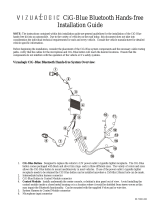
is due to the characteristics of a mechanism
the product is equipped with.
If the program that is activated when the
product is first powered on works properly,
the front panel will automatically move into
the position (initial setting angle) shown in
(Fig. 2).
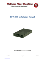
(Fig. 1)
(Fig. 2)
After the Installation
After the installation, perform the Initial Setup
by referring to the instruction manual.
¤
• Mounting and wiring this product requires
skills and experience. For safety’s sake, leave the
mounting and wiring work to professionals.
• Make sure to ground the unit to a negative 12V
DC power supply.
• Do not install the unit in a spot exposed to direct
sunlight or excessive heat or humidity. Also avoid
places with too much dust or the possibility of
water splashing.
• Do not use your own screws. Use only the screws
provided. If you use the wrong screws, you could
damage the unit.
• If the power is not turned ON (“PROTECT” is
displayed), the speaker wire may have a short-
circuit or touched the chassis of the vehicle and
the protection function may have been activated.
Therefore, the speaker wire should be checked.
• If your car’s ignition does not have an ACC
position, connect the ignition wires to a power
source that can be turned on and off with the
ignition key. If you connect the ignition wire to a
power source with a constant voltage supply, as
with battery wires, the battery may die.
• If the console has a lid, make sure to install the
unit so that the faceplate will not hit the lid when
closing and opening.
• If the fuse blows, first make sure the wires aren’t
touching to cause a short circuit, then replace the
old fuse with one with the same rating.
• Insulate unconnected wires with vinyl tape or
other similar material. To prevent a short circuit,
do not remove the caps on the ends of the
unconnected wires or the terminals.
• Connect the speaker wires correctly to the
terminals to which they correspond. The unit may
be damaged or fail to work if you share the -
wires or ground them to any metal part in the car.
• When only two speakers are being connected
to the system, connect the connectors either to
both the front output terminals or to both the
rear output terminals (do not mix front and rear).
For example, if you connect the + connector
of the left speaker to a front output terminal, do
not connect the - connector to a rear output
terminal.
• After the unit is installed, check whether the brake
lamps, blinkers, wipers, etc. on the car are working
properly.
• Mount the unit so that the mounting angle is 30°
or less.
• This unit has the cooling fan (page 5) to decrease
the internal temperature. Do not mount the unit
in a place where the cooling fan of the unit are
blocked. Blocking these openings will inhibit the
cooling of the internal temperature and result in
malfunction.
• Do not press hard on the panel surface when
installing the unit to the vehicle. Otherwise scars,
damage, or failure may result.
• Reception may drop if there are metal objects
near the Bluetooth antenna.
Bluetooth antenna unit
¤ CAUTION
Install this unit in the console of your
vehicle.
Do not touch the metal part of this unit
during and shortly after the use of the
unit. Metal part such as the heat sink and
enclosure become hot.