Hitachi L300P User manual
- Category
- Power adapters & inverters
- Type
- User manual
This manual is also suitable for


Hitachi’s L300P Series Variable Fre
Increased Energy Savings for Your
AUTOMATIC ENERGY-SAVING
FUNCTION
With its Automatic Energy-saving Function, the L300P delivers
“real-time” energy-saving operation for your fan and pump
applications. The function insures that motor operates at minimum
current in response to the torque required by the load.
ENHANCED INPUT/OUTPUT TERMINALS
Three relay output terminals are provided
as standard for flexible interface to external
control systems.
ANALOG OUTPUT MONITOR
In addition to PWM monitor(FM), programmable analog output monitors are also available for
both voltage(0
-
10VDC) and current(4
-
20mA) at AM and AMI terminals of the L300P.
INTELLIGENT INPUT/OUTPUT TERMINAL SYSTEM
The L300P features an intelligent control
terminal system, which allows necessary
drive I/O functions to be freely programmed.
Input terminals can be selected for either
sink or source type logic.
EASY- TO-USE OPERATOR PANEL
Output frequency
Output current
Rotation direction
Process variable, PID feedback
Intelligent input terminal status
INTELLIGENT RELAY OUTPUTS
NO contact
X
2 NO-NC contact
X
1
AL212C 12A 11C 11A AL0 AL1
L300P's digital operator panel supports various monitoring functions.
Cumulative power-on time
Trip event
Trip history
Warning code
Intelligent output terminal status
Scaled output frequency
Output voltage
Power
Cumulative RUN time
Example of Energy Savings (Fan)
Operation by Inlet vane
and damper
Operation by
v/f control
Operation by Automatic
Energy-saving Function
Amount of energy
to be saved
Power Consumption
Frequency
[Sink type logic]
CM1
FW
L300P
P24
FW
L300P
[Source type logic]
Upper SystemUpper System
+Power Supply
1
WIDE RANGE OF APPLICATION SPECIFIC FUNCTIONS
WIDE RANGE OF APPLICATION SPECIFIC FUNCTIONS

quency Drive Delivers
Fan and Pump Applications!
CONTENTS
Hitachi
Inverter
L300P
Hitachi
Inverter
L300P
Ease of
Operation
Global
Standards
High-
performance
Easy
Maintenance
Compact
Size
FEATURES
STANDARD SPECIFICATIONS
DIMENSIONS
OPERATION and PROGRAMMING
FUNCTION LIST
TERMINALS
PROTECTIVE FUNCTIONS
CONNECTING DIAGRAM
CONNECTING TO PLC
WIRING and ACCESSORIES
ACCESSORIES
FOR COMPACT PANEL
TORQUE CHARACTERISTICS, DERATING DATA
FOR CORRECT OPERATION
1
-
4
5
-
7
8
-
11
12
13
-
16
17
-
18
19
20
-
21
22
23
24
-
26
27
28
29
-
30
2
FOR OPTIMAL OPERATION
FOR OPTIMAL OPERATION
PAGE
Hitachi variable frequency
drives (inverters) in this
brochure are produced at the
factory registered under the
ISO 14001 standard for
environmental management
system and the ISO 9001
standard for inverter quality
management system.
ISO 14001
EC97J1095
ISO 9001
JQA-1153

Eliminates control rewiring when field replacing the L300P.
The L300P’s compact size helps economize panel space.
Installation area is reduced by approximately 30% from
that of our previous series.
(Comparison of 11kW (15HP))
You can select frequently used commands and store
them for fast reference.
RS485 is provided as standard for ASCII serial
communication.
Optional PC drive configuration software which runs on
Windows
®
Operating System.
Output frequency can be controlled by the integral
potentiometer provided as standard on the OPE-SR.
The OPE-SR can be removed for remote control, and has
an easy-to-see 4-digit display and LEDs to indicate the
unit being monitored (i.e. frequency, amps, power, etc.).
A multilingual operator (English, French, German, Italian,
Spanish, and Portuguese) with copy function (SRW-
0EX) and a digital operator without potentiometer (OPE-
S) are also available as options.
3
EASY-REMOVABLE
COOLING FAN
AND DC BUS CAPACITOR
REMOVABLE CONTROL
CIRCUIT TERMINALS
EASE OF OPERATION WITH
DIGITAL OPERATOR (OPE-SR)
USER SELECTION OF
COMMAND FUNCTIONS
(“Quick Menu”)
BUILT-IN RS485
PROGRAMMING SOFTWARE
Cooling fan(s) and DC bus
capaci-tors can be easily
changed in the field. A
fan ON/OFF function can
be activated to provide
longer cooling fan life.
Control Circuit Terminals

EMI filters to meet European EMC (EN61800-3, EN55011)
and low-voltage directive (EN50178) are available for system
conformance.
CE, UL, c-UL, C-Tick approvals.
Standard enclosure protection for the L300P is IP20 (NEMA1*).
For IP54 (NEMA12), please contact Hitachi sales office.
MODEL NAME INDICATION
Series Name
Version number
U:UL version for North America
E:CE version for Europe
L:3-phase 200V Class
H:3-phase 400V Class
F:With Digital Operator
Power Source
Applicable Motor Capacity
L300P
-
015
L F U 2
4
EMI FILTER
HARMONICS MITIGATION
CONFORMITY TO GLOBAL
STANDARDS
NETWORK COMPATIBILITY
The L300P can communicate with DeviceNet™,
PROFIBUS
®
, LONWORKS
®
, Modbus
®
RTU
*1
,
and Ethernet™
*2
with communication options.
*1, *2: Being planned
*
NEMA 1 applies up to 30kW. An optional wire-entry conduit box is required for 37kW to
75kW models to meet NEMA 1 rating.
Windows is a registered trademark of Microsoft Corp. in the U.S. and other countries.
DeviceNet is a trademark of Open DeviceNet Vendor Association.
PROFIBUS is a registered trademark of Profibus Nutzer Organization.
Disturbance voltage of the main circuit power supply and
of the control circuit power supply has been improved by
approximately 15dB( V) and 20dB( V) respectively compared
to our previous model(J300), resulting in significant reductions
to noise interference with sensors and other peripheral
devices.
REDUCED NOISE FROM MAIN
CIRCUIT POWER SUPPLY AND
CONTROL CIRCUIT POWER SUPPLY
CONTROL OF VOLTAGE OF
MICRO SERGE
11
(
15
)
L300P-110LFU2
L300P-110HFU2/E2
15
(
20
)
L300P-150LFU2
L300P-150HFU2/E2
18.5
(
25
)
L300P-185LFU2
L300P-185HFU2/E2
22
(
30
)
L300P-220LFU2
L300P-220HFU2/E2
30
(
40
)
L300P-300LFU2
L300P-300HFU2/E2
MODEL CONFIGURATION
Applicable Motor Capacity
in kW (HP)
3-phase 200V class 3-phase 400V class
1.5
(
2
)
L300P-015LFU2
L300P-015HFU2/E2
2.2
(
3
)
L300P-022LFU2
L300P-022HFU2/E2
3.7
(
5
)
L300P-037LFU2
L300P-040HFU2/E2
5.5
(
7.5
)
L300P-055LFU2
L300P-055HFU2/E2
7.5
(
10
)
L300P-075LFU2
L300P-075HFU2/E2
37
(
50
)
L300P-370LFU2
L300P-370HFU2/E2
45
(
60
)
L300P-450LFU2
L300P-450HFU2/E2
55
(
75)
75
(
100
)
L300P-750HFU2/E2
90
(
125
)
L300P-900HFU2/E2
110
(1
50
)
L300P-1100HFU2/E2
132
(
175
)
L300P-1320HFU2/E2
L300P-550LFU2
L300P-550HFU2/E2
L300P-750LFU2
IMPROVEMENT OF ENVIRONMENT
The printed circuit board inside an inverter is varnish
coating specification as standard.
20
40
60
80
100
0
.2 .3 .5 .7 1 5 7 10 30203
J300-055LFU
L300P-055LFU2
40
60
70
80
90
100
0
.2 .3 .5 .7 1 5 7 10 20 30
Frequency(MHz)
Frequency(MHz)
J300 series
J300 series
L300P series
L300P series
J300-220LFU
Disturbance voltage of the main circuit power supply
(It does not comply with European EMC directive. To meet the EMC directive,
please use an EMI filter.)
Disturbance voltage of the control circuit power supply
(Disturbance voltage of terminal L or CM1)
Disturbance voltage [dB(µV)]Disturbance voltage [dB(µV)]
L300P-220LFU2
Terminals for the connection of a DC Reactor are provid-
ed as standard for harmonics suppression.
Suppressing the motor terminal voltage less than
2xE [V]
by improving the control method of PWM output.
Input voltage:400VAC(In the case)
Motor terminal voltage:1,131V(400V
X
2
X
2

5
STANDARD SPECIFICATIONS
Model
L300P-XXX
Enclosure (
*
2)
Applicable motor (4-pole, kW(HP)) (
*
3)
Rated capacity
(kVA)
Rated input voltage
Rated input current (A)
Required power supply capacity (kVA)
Rated output voltage (
*
4)
Rated output current (continuous)(A)
Control method
Output frequency range (
*
5)
Frequency accuracy
Frequency resolution
V/f characteristics
Overload capacity
Acceleration/deceleration time
Braking
Input
signal
Intelligent
input terminals
(Assign five functions
to terminals)
Thermistor input
Intelligent output
terminals
Intelligent monitor
output terminals
Output
signal
Display monitor
Other user-settable parameters
Carrier frequency range
Protective functions
Ambient operating /storage
temperature
(
*
7
)
/humidity
Vibration
(
*
8
)
Location
Color
Operator
Weight kg
(
lbs.
)
Options
Environmental
conditions
Item
200V Class
Up to 30kW.
An optional conduit box is required for 37kW to 55kW to meet NEMA 1 .
The protection method conforms to JEM 1030 / NEMA(U.S.).
The applicable motor refers to Hitachi standard 3-phase motor (4-pole).
To use other motors, care must be taken to prevent the rated motor current
(50Hz) from exceeding the rated output current of the inverter.
The output voltage decreases as the main power supply voltage decreases
except for the use of AVR function.
To operate the motor beyond 50/60Hz, please consult with the motor
manufacturer about the maximum allowable rotation speed.
Braking resistor is not integrated in the inverter. Please install optional
braking resistor or dynamic braking unit when large braking torque is
required.
Storage temperature refers to the temperature in transportation.
Conforms to the test method specified in JIS C0040(1999).
When using the inverter from 40º to 50ºC ambient, the output current of
the inverter must be derated (see the next section on derating curves).
110LFU2
—
11(15)
15.2
18.2
48
22
44
30
(
66
)
30
(
66
)
20
(
44
)
12
(
26.4
)
12
(
26.4
)
12
(
26.4
)
5
(
11
)
5
(
11
)
150LFU2
—
15(20)
20.0
24.1
64
30
58
185LFU2
—
18.5(25)
25.2
30.3
80
37
73
220LFU2
—
22(30)
29.4
35.3
94
44
85
300LFU2
—
30(40)
39.1
46.9
124
60
113
370LFU2
—
37(50)
48.4
58.1
154
74
140
450LFU2
—
45(60)
58.5
70.2
186
90
169
550LFU2
—
55(75)
72.7
87.2
231
110
210
50
(
110
)
750LFU2
—
75(100)
93.5
112.2
297
150
270
Operator
Potentiometer
External signal
External port
Operator
External signal
External port
Dynamic braking
(Short-time) (
*
6)
DC braking
Frequency
setting
Forward/
reverse
Start/stop
UL version
CE version
200V
240V
IP20 (NEMA 1) (
*
1)
3-phase (3-wire) 200
-
2
40V (
±
10%), 50/60Hz
3-phase (3-wire) 200
-
240V (Corresponding to input voltage)
Line to line sine wave PWM
0.1
-
400Hz
Digital:
±
0.01% of the maximum frequency, Analog:
±
0.2%(25
±
10°C)
Digital setting: 0.01Hz, Analog setting: (Maximum frequency)/4,000 (O terminal: 12-bit 0
–
10V, O2 terminal: 12-bit
-
10
–
+10V)
V/f optionally variable, V/f control (Constant torque, reduced torque)
120% for 60sec., 150% for 0.5sec.
0.01
-
3,600sec. (Linear/curve, accel./decel. selection), Two-stage accel./decel.
Up and Down keys
Potentiometer
DC 0
-
10V,
–
10
-
+10V (input impedance 10k ), 4
-
20mA (input impedance 100 )
RS-485 interface
Run key/Stop key (FW/RV can be set by function command.)
FW RUN/STOP (NO contact), RV set by terminal assignment (NO/NC selection), 3-wire input available
Set by RS-485
External dynamic braking unit (option)
Built-in BRD circuit(optional resistor)
RV(Reverse), CF1-CF4(Multispeed command), JG(Jogging), DB(External DC braking),
SET(Second motor constants setting), 2CH(Second accel./decel.), FRS(Free-run stop), EXT(External trip),
USP(Unattended start protection), CS(Change to/from commercial power supply),SFT(Software lock),
AT(Analog input selection), RS(Reset), STA(3-wire start), STP(3-wire stop), F/R(3-wire fwd./rev.), PID(PID On/Off),
PIDC(PID reset), UP/DWN(Remote-controlled accel./decel.) UDC(Remote-controlled data clearing),
SF1-SF7(Multispeed bit command 1-7), OLR(Overload limit change), ROK(RUN Permissive) and NO(Not selected)
Performs at start; under set frequency at deceleration, or via an external input
(braking force, time, and operating frequency).
Assign three functions to two NO contacts and one NO-NC combined contact
(RUN, FA1, FA2, OL, OD, AL, FA3, IP, UV, RNT, ONT RMD and THM)
Output frequency, output current, scaled value of output frequency, trip history, I/O terminal condition, input power, output voltage
EMI filters, input/output reactors, DC reactors, radio noise filters, braking resistors, braking units, LCR filter, communi-
cation cables, Network interface cards
0.5
-
12kHz
Altitude 1,000m or less, indoors (no corrosive gases or dust)
*
1:
*
2:
*
3:
*
4:
*
5:
*
6:
*
7:
*
8:
*
9:
5.9m/s
2
(0.6G), 10
-
55Hz 2.9m/s
2
(0.3G), 10
-
55Hz
Blue Gray (Bezel for digital operator is blue)
Over-current protection, overload protection, braking resistor overload protection, over-voltage protection, EEPROM
error, under-voltage error, CT(Current transformer) error, CPU error, external trip, USP error, ground fault, input over-
voltage protection, instantaneous power failure, option 1 connection error, option 2 connection error, inverter thermal
trip, phase failure detection, IGBT error, thermistor error
V/f free-setting (up to 7 points), frequency upper/lower limit, frequency jump, accel./decel. curve selection, manual
torque boost value and frequency adjustment, analog meter tuning, starting frequency, carrier frequency, electronic ther-
mal protection level, external frequency output zero/span reference, external frequency input bias start/end, analog input
selection, retry after trip, reduced voltage soft start, overload restriction, automatic energy-saving
OPE-SR(4-digit LED with potentiometer) / OPE-SRE(4-digit LED with potentiometer, English overlay)
Optional: OPE-S(4-digit LED), SRW-0EX(Multilingual (English,French, German, Italian, Spanish, and Portuguese)
operator with copy function), ICS-1,3(Cable for operators(1m, 3m))
–
10
-
40°C(
*
9) /
–
20
-
65°C / 25
-
90%RH (No condensation)
Analog voltage, analog current, PWM output
One terminal(PTC)
015LFU2
—
1.5(2)
2.5
3.1
8.3
3
7.5
022LFU2
—
2.2(3)
3.6
4.3
12
4.4
10.5
037LFU2
—
3.7(5)
5.7
6.8
18
7.4
16.5
055LFU2
—
5.5(7.5)
8.3
9.9
26
11
24
075LFU2
—
7.5(10)
11
13.3
35
15
32
3.5 (7.7) 3.5 (7.7) 3.5 (7.7) 3.5 (7.7)
5 (11)

6
Model
L300P-XXX
Enclosure (
*
2)
Applicable motor (4-pole, kW(HP)) (
*
3)
Rated capacity
(kVA)
Rated input voltage
Rated input current (A)
Required power supply capacity (kVA)
Rated output voltage (
*
4)
Rated output current (continuous)(A)
Control method
Output frequency range (
*
5)
Frequency accuracy
Frequency resolution
V/f characteristics
Overload capacity
Acceleration/deceleration time
Braking
Input
signal
Intelligent
input terminals
(Assign five functions
to terminals)
Thermistor input
Intelligent output
terminals
Intelligent monitor
output terminals
Output
signal
Display monitor
Other user-settable parameters
Carrier frequency range
Protective functions
Ambient operating /storage
temperature
(
*
7
)
/humidity
Vibration
(
*
8
)
Location
Color
Operator
Weight kg
(
lbs.
)
Options
Environmental
conditions
Item
400V Class
Up to 30kW.
An optional conduit box is required for 37kW to 55kW to meet NEMA 1 .
The protection method conforms to JEM 1030 / NEMA(U.S.).
The applicable motor refers to Hitachi standard 3-phase motor (4-pole).
To use other motors, care must be taken to prevent the rated motor current
(50Hz) from exceeding the rated output current of the inverter.
The output voltage decreases as the main power supply voltage decreases
except for the use of AVR function.
To operate the motor beyond 50/60Hz, please consult with the motor
manufacturer about the maximum allowable rotation speed.
Braking resistor is not integrated in the inverter. Please install optional
braking resistor or dynamic braking unit when large braking torque is
required.
Storage temperature refers to the temperature in transportation.
Conforms to the test method specified in JIS C0040(1999).
When using the inverter from 40º to 50ºC ambient, the output current of
the inverter must be derated (see the next section on derating curves).
110HFU2
110HFE2
11(15)
15.2
18.2
24
22
22
12
(
26.4
)
12
(
26.4
)
12
(
26.4
)
5
(
11
)
5
(
11
)
185HFU2
185HFE2
18.5(25)
25.6
30.7
41
37
37
220HFU2
220HFE2
22(30)
29.7
35.7
47
44
43
300HFU2
300HFE2
30(40)
39.4
47.3
63
60
57
Operator
Potentiometer
External signal
External port
Operator
External signal
External port
Dynamic braking
(Short-time) (
*
6)
DC braking
Frequency
setting
Forward/
reverse
Start/stop
UL version
CE version
400V
480V
IP20 (NEMA 1) (
*
1)
3-phase (3-wire) 380
-
4
80V (
±
10%), 50/60Hz
3-phase (3-wire) 380
-
480V (Corresponding to input voltage)
Line to line sine wave PWM
0.1
-
400Hz
Digital:
±
0.01% of the maximum frequency, Analog:
±
0.2%(25
±
10°C)
Digital setting: 0.01Hz, Analog setting: (Maximum frequency)/4,000 (O terminal: 12-bit 0
–
10V, O2 terminal: 12-bit
-
10
–
+10V)
V/f optionally variable, V/f control (Constant torque, reduced torque)
120% for 60sec., 150% for 0.5sec.
0.01
-
3,600sec. (Linear/curve, accel./decel. selection), Two-stage accel./decel.
Up and Down keys
Potentiometer
DC 0
-
10V,
–
10
-
+10V (input impedance 10k ), 4
-
20mA (input impedance 100 )
RS-485 interface
Run key/Stop key (FW/RV can be set by function command.)
FW RUN/STOP (NO contact), RV set by terminal assignment (NO/NC selection), 3-wire input available
Set by RS-485
External dynamic braking unit
(option)
Built-in BRD circuit(optional resistor)
RV(Reverse), CF1-CF4(Multispeed command), JG(Jogging), DB(External DC braking),
SET(Second motor constants setting), 2CH(Second accel./decel.), FRS(Free-run stop), EXT(External trip),
USP(Unattended start protection), CS(Change to/from commercial power supply),SFT(Software lock),
AT(Analog input selection), RS(Reset), STA(3-wire start), STP(3-wire stop), F/R(3-wire fwd./rev.), PID(PID On/Off),
PIDC(PID reset), UP/DWN(Remote-controlled accel./decel.) UDC(Remote-controlled data clearing),
SF1-SF7(Multispeed bit command 1-7), OLR(Overload limit change), ROK(RUN Permissive) and NO(Not selected)
Performs at start; under set frequency at deceleration, or via an external input
(braking force, time, and operating frequency).
Assign three functions to two NO contacts and one NO-NC combined contact
(RUN, FA1, FA2, OL, OD, AL, FA3, IP, UV, RNT, ONT RMD and THM)
Output frequency, output current, scaled value of output frequency, trip history, I/O terminal condition, input power, output voltage
EMI filters, input/output reactors, DC reactors, radio noise filters, braking resistors, braking units, LCR filter, communi-
cation cables, Network interface cards
0.5
-
12kHz
Altitude 1,000m or less, indoors (no corrosive gases or dust)
*
1:
*
2:
*
3:
*
4:
*
5:
*
6:
*
7:
*
8:
*
9:
5.9m/s
2
(0.6G), 10
-
55Hz
Blue
Over-current protection, overload protection, braking resistor overload protection, over-voltage protection, EEPROM
error, under-voltage error, CT(Current transformer) error, CPU error, external trip, USP error, ground fault, input over-
voltage protection, instantaneous power failure, option 1 connection error, option 2 connection error, inverter thermal
trip, phase failure detection, IGBT error, thermistor error
V/f free-setting (up to 7 points), frequency upper/lower limit, frequency jump, accel./decel. curve selection, manual
torque boost value and frequency adjustment, analog meter tuning, starting frequency, carrier frequency, electronic ther-
mal protection level, external frequency output zero/span reference, external frequency input bias start/end, analog input
selection, retry after trip, reduced voltage soft start, overload restriction, automatic energy-saving
OPE-SR(4-digit LED with potentiometer) / OPE-SRE(4-digit LED with potentiometer, English overlay)
Optional: OPE-S(4-digit LED), SRW-0EX(Multilingual (English,French, German, Italian, Spanish, and Portuguese)
operator with copy function), ICS-1,3(Cable for operators(1m, 3m))
–
10
-
40°C(
*
9) /
–
20
-
65°C / 25
-
90%RH (No condensation)
Analog voltage, analog current, PWM output
One terminal(PTC)
150HFU2
150HFE2
15(20)
20.0
24.1
32
30
29
015HFU2
015HFE2
1.5(2)
2.6
3.1
4.2
3
3.8
022HFU2
022HFE2
2.2(3)
3.6
4.4
5.8
4.4
5.3
040HFU2
040HFE2
4.0(5)
5.9
7.1
9.5
8
8.6
055HFU2
055HFE2
5.5(7.5)
8.3
9.9
13
11
12
075HFU2
075HFE2
7.5(10)
11
13.3
18
15
16
3.5 (7.7) 3.5 (7.7) 3.5 (7.7) 3.5 (7.7)
5 (11)

7
STANDARD SPECIFICATIONS
Model
L300P-XXX
Enclosure (
*
2)
Applicable motor (4-pole, kW(HP)) (
*
3)
Rated capacity
(kVA)
Rated input voltage
Rated input current (A)
Required power supply capacity (kVA)
Rated output voltage (
*
4)
Rated output current (continuous)(A)
Control method
Output frequency range (
*
5)
Frequency accuracy
Frequency resolution
V/f characteristics
Overload capacity
Acceleration/deceleration time
Braking
Input
signal
Intelligent
input terminals
(Assign five functions
to terminals)
Thermistor input
Intelligent output
terminals
Intelligent monitor
output terminals
Output
signal
Display monitor
Other user-settable parameters
Carrier frequency range
Protective functions
Ambient operating /storage
temperature
(
*
7
)
/humidity
Vibration
(
*
8
)
Location
Color
Operator
Weight kg
(
lbs.
)
Options
Environmental
conditions
Item
400V Class
Up to 30kW.
An optional conduit box is required for 37kW to 55kW to meet NEMA 1 .
The protection method conforms to JEM 1030 / NEMA(U.S.).
The applicable motor refers to Hitachi standard 3-phase motor (4-pole).
To use other motors, care must be taken to prevent the rated motor current
(50Hz) from exceeding the rated output current of the inverter.
The output voltage decreases as the main power supply voltage decreases
except for the use of AVR function.
To operate the motor beyond 50/60Hz, please consult with the motor
manufacturer about the maximum allowable rotation speed.
Braking resistor is not integrated in the inverter. Please install optional
braking resistor or dynamic braking unit when large braking torque is
required.
Storage temperature refers to the temperature in transportation.
Conforms to the test method specified in JIS C0040(1999).
When using the inverter from 40º to 50ºC ambient, the output current of
the inverter must be derated (see the next section on derating curves).
30
(
66
)
30
(
66
)
20
(
44
)
370HFU2
370HFE2
37(50)
48.4
58.1
77
74
70
450HFU2
450HFE2
45(60)
58.8
70.1
94
90
85
550HFU2
550HFE2
55(75)
72.7
87.2
116
110
105
30
(
66
)
750HFU2
750HFE2
75(100)
93.5
112.2
149
150
135
Operator
Potentiometer
External signal
External port
Operator
External signal
External port
Dynamic braking
(Short-time) (
*
6)
DC braking
Frequency
setting
Forward/
reverse
Start/stop
UL version
CE version
400V
480V
Line to line sine wave PWM
0.1
-
400Hz
Digital:
±
0.01% of the maximum frequency, Analog:
±
0.2%(25
±
10°C)
Digital setting: 0.01Hz, Analog setting: (Maximum frequency)/4,000 (O terminal: 12-bit 0
–
10V, O2 terminal: 12-bit
-
10
–
+10V)
V/f optionally variable, V/f control (Constant torque, reduced torque)
120% for 60sec., 150% for 0.5sec.
0.01
-
3,600sec. (Linear/curve, accel./decel. selection), Two-stage accel./decel.
Up and Down keys
Potentiometer
DC 0
-
10V,
–
10
-
+10V (input impedance 10k ), 4
-
20mA (input impedance 100 )
RS-485 interface
Run key/Stop key (FW/RV can be set by function command.)
FW RUN/STOP (NO contact), RV set by terminal assignment (NO/NC selection), 3-wire input available
Set by RS-485
External dynamic braking unit (option)
RV(Reverse), CF1-CF4(Multispeed command), JG(Jogging), DB(External DC braking),
SET(Second motor constants setting), 2CH(Second accel./decel.), FRS(Free-run stop), EXT(External trip),
USP(Unattended start protection), CS(Change to/from commercial power supply),SFT(Software lock),
AT(Analog input selection), RS(Reset), STA(3-wire start), STP(3-wire stop), F/R(3-wire fwd./rev.), PID(PID On/Off),
PIDC(PID reset), UP/DWN(Remote-controlled accel./decel.) UDC(Remote-controlled data clearing),
SF1-SF7(Multispeed bit command 1-7), OLR(Overload limit change), ROK(RUN Permission) and NO(Not selected)
Performs at start; under set frequency at deceleration, or via an external input
(braking force, time, and operating frequency).
Assign three functions to two NO contacts and one NO-NC combined contact
(RUN, FA1, FA2, OL, OD, AL, FA3, IP, UV, RNT, ONT, RMD and THM)
Output frequency, output current, scaled value of output frequency, trip history, I/O terminal condition, input power, output voltage
EMI filters, input/output reactors, DC reactors, radio noise filters, braking resistors,
braking units, LCR filter, communication cables, Network interface cards
Altitude 1,000m or less, indoors (no corrosive gases or dust)
*
1:
*
2:
*
3:
*
4:
*
5:
*
6:
*
7:
*
8:
*
9:
2.9m/s
2
(0.3G), 10
-
55Hz
Gray (Bezel for digital operator is blue)
Over-current protection, overload protection, braking resistor overload protection, over-voltage protection, EEPROM
error, under-voltage error, CT(Current transformer) error, CPU error, external trip, USP error, ground fault, input over-
voltage protection, instantaneous power failure, option 1 connection error, option 2 connection error, inverter thermal
trip, phase failure detection, IGBT error, thermistor error
V/f free-setting (up to 7 points), frequency upper/lower limit, frequency jump, accel./decel. curve selection, manual
torque boost value and frequency adjustment, analog meter tuning, starting frequency, carrier frequency, electronic ther-
mal protection level, external frequency output zero/span reference, external frequency input bias start/end, analog input
selection, retry after trip, reduced voltage soft start, overload restriction, automatic energy-saving
OPE-SR(4-digit LED with potentiometer) / OPE-SRE(4-digit LED with potentiometer, English overlay)
Optional: OPE-S(4-digit LED), SRW-0EX(Multilingual (English,French, German, Italian, Spanish, and Portuguese)
operator with copy function), ICS-1,3(Cable for operators(1m, 3m))
–
10
-
40°C(
*
9) /
–
20
-
65°C / 25
-
90%RH (No condensation)
Analog voltage, analog current, PWM output
One terminal(PTC)
900HFU2
900HFE2
90 (125)
110.8
133.0
176
180
160
1100HFU2
1100HFE2
110 (150)
135.0
162.1
215
220
195
1320HFU2
1320HFE2
132 (175)
159.3
191.2
253
264
230
0.5
-
8kHz
60
(
132
)
60
(
132
)
80
(
176
)
0.5
-
12kHz
IP20 (NEMA 1) (
*
1)
IP00
3-phase (3-wire) 380
-
480V (
±
10%), 50/60Hz
3-phase (3-wire) 380
-
480V (Corresponding to input voltage)

8
L300P-075
-
150LFU2, 075
-
150HFE2, 075
-
150HFU2
DIMENSIONS
40(1.57)
LFU2 HFU2 type(055LFU2 HFU2)
Conduit box to meet NEMA1 rating
75(2.95)
70(2.76)
LFU2 HFU2 type
Conduit box to meet NEMA1 rating
80(3.15)
Exhaust
Air intake
Wall
79
(
3.11
)
170
(
6.69
)
80
(
3.15
)
24.5
(
0.97
)
82
(
3.23
)
203
(
7.99
)
210
(
8.27
)
7
(
0.28
)
189
(
7.44
)
246
(
9.69
)
260
(
10.24
)
189
(
7.44
)
7
(
0.28
)
170
(
6.69
)
2- 7
(
0.28
)
3- 25
(
0.98
)
Wiring hole
[Unit:mm (inch)]
Inches for reference only
L300P-015
-
055LFU2
015
-
055HFU2
015
-
055HFE2
Exhaust
Air intake
Wall
241(9.49)
164(6.46) 79(3.11)
255(10.04)
150(5.91)
80(3.15)
25(0.98)
130(5.12)
6(0.24)
7(0.28)
140(5.51)
143(5.63)
130(5.12)
69(2.72)
Wiring Hole
Digital Operator
3
-
20
(
0.78
)
2
-
6 ( 0.24)
[Unit:mm (inch)]
Inches for reference only
Digital Operator
8.5
(
0.33
)
8.5
(
0.33
)

9
DIMENSIONS
147(5.79)
LFU2 HFU2 type
Conduit box to meet NEMA1 rating
104(4.09)
L300P-185
-
300LFU2,
185
-
300HFE2,
185
-
300HFU2
L300P-370LFU2,
370HFE2,
370HFU2
Exhaust
Air intake
Wall
79
(
3.11
)
80
(
3.15
)
24.5
(
0.97
)
8.5
(
0.33
)
273
(
10.75
)
83
(
3.27
)
7
(
0.28
)
244
(
9.61
)
45
(
1.77
)
80
(
3.15
)
9.5
(
0.37
)
190
(
7.48
)
229
(
9.02
)
390
(
15.35
)
376
(
14.80
)
250
(
9.84
)
2- 7
(
0.28
)
229
(
9.02
)
4- 29.5
(
1.16
)
Wiring hole
[Unit:mm (inch)]
Inches for reference only
[Unit:mm (inch)]
Inches for reference only
2-10(0.39)
310(12.20)
265(10.43)
195(7.68)
540(21.26)
510(20.08)
2- 10( 0.39)
145(5.71)
175(6.89)
Wall
Conduit box to meet NEMA1 rating
(
Optional
)
Air intake
Exhaust
8.5
(
0.33
)
74(2.91)
79
(
3.11
)
271
(
10.67
)
Digital Operator
Digital Operator

10
L300P-750LFU2
700(27.56)
670(26.38)
480(18.90)
380(14.96)
8.5(0.33)
2
-
12(0.47)
2 12(0.47)
160(6.30)
250(9.84)
Wall
Air intake
Exhaust
Conduit box to meet NEMA 1 rating
(Optional)
190(7.48)
104(4.09)
L300P-450
-
550LFU2,
450
-
750HFE2,
450
-
750HFU2
[Unit:mm (inch)]
Inches for reference only
[Unit:mm (inch)]
Inches for reference only
550(21.65)
520(20.47)
390(15.35)
300(11.81)
2
-
12( 0.47)
2-12(0.47)
250
(
9.84
)
155
(
6.01
)
Wall
Air intake
Exhaust
8.5
(
0.33
)
185
(
7.28
)
Conduit box to meet NEMA1 rating
(
Optional
)
90(3.54)
Digital Operator
32.5
(
1.28
)
80
(
3.15
)
79
(
3.11
)
277
(
10.91
)
79
(
3.11
)
352
(
13.87
)
Digital Operator
125
(
4.92
)
80
(
3.15
)

11
DIMENSIONS
L300P-900HFE2, HFU2
-1100HFE2, HFU2
L300P-1320HFE2, HFU2
Exhaust
Air intake
740 (29.13)
710 (27.95)
2
-
12 (0.47)
270 (10.63)
Wall
8.5 (0.33)
Exhaust
Air intake
Wall
270(10.63)
390
(
15.35
)
300
(
11.81
)
2
-
12
(
0.47
)
670
(
26.38
)
700
(
27.56
)
8.5(0.33)
380 (14.76)
480 (18.90)
[Unit:mm (inch)]
Inches for reference only
[Unit:mm (inch)]
Inches for reference only
2
-
12( 0.47)
Digital Operator
32.5
(
1.28
)
80
(
3.15
)
62.5
(
2.46
)
80
(
3.15
)
79
(
3.11
)
357
(
14.06
)
79
(
3.11
)
480
(
18.91
)
Digital Operator
2 12(0.47)

12
OPERATION and PROGRAMMING
Shows drive's status.
Press to run the motor.
Press to stop the drive or
reset an alarm.
Lights when the power input to
the drive is ON.
Indicates the unit associated
with the parameter display.
Press to write the new value to
the EEPROM.
Press up or down to sequence through
parameters and functions shown on the
display, and increment/decrement values.
Press to set or monitor a
parameter value.
Parameter Display Power LED
Display Unit LEDs
Potentiometer
Store Key
Up/Down Keys
Monitor LEDs
RUN Key
STOP/RESET Key
Function Key
Displays frequency, motor cur-
rent, rotational speed of the
motor, and an alarm code.
L300P Series can be easily operated with the digital operator (OPE-SR) provided as standard. The Digital operator can
also be detached and used for remote-control. A multilingual (English, French, German Italian, Spanish, and Portuguese)
operator with copy function (SRW-0EX) or a digital operator without potentiometer(OPE-S) is also available as an option.
(For US version, OPE-SRE (English overlay with potentiometer) is provided as standard.)
(
1
)
or the value previously
monitored is displayed.
(
1
)
or the value previously
monitored is displayed.
(
2
)
The motor runs at the frequency
set by the potentiometer.
(
3
)
The motor stops.
(
2
)
Function code appears.
(
3
)
appears.
(
5
)
appears.
(
6
)
Preset value is displayed.
(
7
)
Newly set value is displayed.
(
8
)
Returns to and
the setting is complete.
(
4
)
or the code
number set in the end of
last setting is displayed.
(
1
)
or the value previously
monitored is displayed.
1. Setting the maximum output frequency
2. Running the motor(by potentiometer)
3. Monitoring output current value
(
Output frequency monitor
)
FUNC
STR
MIN MAX
Hz
V
A
%
POWER
ALARM
RUN
PRG
kW
FUNC
MIN MAX
Hz
V
A
%
POWER
ALARM
RUN
PRG
kW
FUNC
MIN MAX
Hz
V
A
%
POWER
ALARM
RUN
PRG
kW
MIN MAX
Hz
V
A
%
POWER
ALARM
RUN
PRG
kW
MIN MAX
Hz
V
A
%
POWER
ALARM
RUN
PRG
kW
MIN MAX
Hz
V
A
%
POWER
ALARM
RUN
PRG
kW
MIN MAX
Hz
V
A
%
POWER
ALARM
RUN
PRG
kW
MIN MAX
Hz
V
A
%
POWER
ALARM
RUN
PRG
kW
MIN MAX
Hz
V
A
%
POWER
ALARM
RUN
PRG
kW
MIN MAX
Hz
V
A
%
POWER
ALARM
RUN
PRG
kW
MIN MAX
Hz
V
A
%
POWER
ALARM
RUN
PRG
kW
MIN MAX
Hz
V
A
%
POWER
ALARM
RUN
PRG
kW
MIN MAX
Hz
V
A
%
POWER
ALARM
RUN
PRG
kW
MIN MAX
Hz
V
A
%
POWER
ALARM
RUN
PRG
kW
MIN MAX
Hz
V
A
%
POWER
ALARM
RUN
PRG
kW
Power
on
Power
on
Power
on
Press
until appears.
Press
to set desired value.
Press
until
appears.
Press key.
Press key.
Press key.
Press key
to store the value.
*To run the motor, go
back to monitor mode
or basic setting mode.
Press key to stop the motor.
Press key and turn the
potentiometer clockwise.
Press key.
Press key.
(
2
)
Function code appears.
(
3
)
appears.
(
4
)
Output current value
is displayed.
Press
until appears.
FUNC
FUNC
FUNC
FUNC
STR
FUNC
STR STR
FUNC
STR
FUNC
STR
FUNC
STR
FUNC
STR
FUNC
STR
FUNC
STR
FUNC
STR
FUNC
STR
FUNC
STR
FUNC
STR
FUNC
STR
FUNC
STR
STOP
RESET
RUN

13
Code
Name
Default Setting
-FE(CE)
-FE(CE)
-FU2(UL)
Run-time
Setting
Run-time Data Edit
(Enabled at b031)
Description
Code
Name
Default Setting
-FU2(UL)
Run-time
Setting
Run-time Data Edit
(Enabled at b031)
Description
d001
d002
d003
d004
d005
d006
d007
d013
d014
d016
d017
d080
d081
d086
d090
F001
F002
F202
F003
F203
F004
A---
b---
C---
H---
P---
U---
A001
A002
A003
A203
A004
A204
A005
A006
A011
A012
A013
A014
A015
A016
A019
A020
A220
A038
A039
Output frequency monitor
Output current monitor
Motor rotational direction monitor
Process variable (PV), PID feedback monitor
Intelligent input terminal status
Intelligent output terminal status
Scaled output frequency monitor
Output voltage monitor
Power monitor
Cumulative RUN time monitor
Cumulative power-on time monitor
Trip count monitor
Trip monitor 1
-
6
Warning monitor
Output frequency setting
Acceleration time (1) setting
Acceleration time (1) setting for second motor
Deceleration time (1) setting
Deceleration time (1) setting for second motor
Motor rotational direction setting
A Group: Standard functions
b Group: Fine tuning functions
C Group: Intelligent terminal functions
H Group: Motor constants functions
P Group: Expansion card functions
U Group: User-selectable menu functions
FUNCTION LIST
Monitoring Functions and Main Profile Parameters
A Group: Standard Functions
0.00
-
99.99/100.0
-
400.0Hz
0.0
-
999.9A
F(Forward) / o(Stop) / r(Reverse)
0.00
-
99.99/100.0
-
999.9/1000.
-
9999./1000
-
9999/ 100
-
999(10,000
-
99,900)
0.00
-
99.99/100.0
-
999.9/1000.
-
9999./1000
-
3996(10,000
-
39,960)
0.0
-
600.0V
0.0
-
999.9kW
0.
-
9999./1000
-
9999/ 100
-
999 (10,000
-
99,900)hr
0.
-
9999./1000
-
9999/ 100
-
999 (10,000
-
99,900)hr
0.
-
9999./1000
-
6553(10,000
-
65,530)
Displays trip event information
Warning code
0.0, Starting frequency to maximum frequency / maximum frequency for second motor
0.01
-
99.99/100.0
-
999.9/1000.
-
3600. sec.
0.01
-
99.99/100.0
-
999.9/1000.
-
3600. sec.
0.01
-
99.99/100.0
-
999.9/1000.
-
3600. sec.
0.01
-
99.99/100.0
-
999.9/1000.
-
3600. sec.
00(Forward) / 01 (Reverse)
Expanded Function
Monitor Mode
Basic SettingAnalog Input Setting
Multispeed and Jogging Frequency Setting
–
–
–
–
–
–
–
–
–
–
–
–
–
–
0.00Hz
30.00s
30.00s
30.00s
30.00s
00
–
–
–
–
–
–
–
–
–
–
–
–
–
–
0.00Hz
60.00s
60.00s
60.00s
60.00s
00
–
–
–
–
–
–
–
–
–
–
–
–
–
–
–
–
–
–
–
–
–
–
–
–
–
–
–
–
Setting Mode
(Example) Terminal FW, 2 and 1 : ON
Terminal 5, 4, and 3 : OFF
(Example) Terminal 12 and 11 : ON
AL :OFF
Frequency source setting
Run command source setting
Base frequency setting
Base frequency setting for second motor
Maximum frequency setting
Maximum frequency setting for second setting
AT selection
O2 selection
O-L input active range start frequency
O-L input active range end frequency
O-L input active range start voltage
O-L input active range end voltage
O-L input start frequency enable
External frequency filter time constant
Multispeed operation selection
Multispeed frequency setting (0)
Multispeed frequency setting (0) for second motor
Multispeed frequency setting (1
-
15)
Jog frequency setting
Jog stop mode
00(Potentiometer) / 01(Terminals) / 02(Operator) / 03(RS485) / 04 (Expansion card 1) / 05(Expansion card 2)
01(Terminals) / 02(Operator) / 03(RS485) / 04 (
Expansion card 1
) / 05(
Expansion card 2
)
30.00Hz-Maximum frequency
30.00Hz-Maximum frequency for second motor
30.00
-
400.0Hz
30.00
-
400.0Hz
00(Selection between O and OI at AT) / 01(Selection between O and O2 at AT)
00(Independent) / 01(Only positive) / 02(Both positive and negative)
0.00
-
400.0Hz
0.00
-
400.0Hz
0.
-
100.%
0.
-
100.%
00(External frequency output zero reference) / 01(0Hz)
1.
-
30. (Sampling time = 2 msec.)
00(Binary: up to 16-stage speed at 4 terminals) / 01(Bit: up to 6-stage speed at 5 terminals)
0.00, Starting frequency to maximum frequency
0.00, Starting frequency to maximum frequency for second motor
0.00, Starting frequency to maximum frequency
0.00, Starting frequency to 9.99Hz
00(Free-run stop/disable during RUN) / 01(Deceleration to stop/ disable during RUN) /
02(DC braking to stop/ disable during RUN) / 03(Free-run stop/ enable during RUN) /
04(Deceleration to stop/ enable during RUN) / 05(DC braking to stop/ enable during
RUN)
A021
I
A035
01
01
50.
50.
50.
50.
00
00
0.00
0.00
0.
100.
01
8.
00
0.00
0.00
0.00
1.00
00
01
01
60.
60.
60.
60.
00
00
0.00
60.00
0.
100.
01
8.
00
0.00
0.00
0.00
1.00
00
= Allowed
= Not permitted
[ ]
= Allowed
= Not permitted
[ ]
FW
5 4321
ON
OFF
AL 12 11
ON
OFF

14
-FE(CE)
Code
Name
Default Setting
-FU2
(
UL
)
Run-time
Setting
Run-time Data Edit
(Enabled at b031)
Description
A041
A241
A042
A242
A043
A243
A044
A244
A045
A051
A052
A053
A054
A055
A056
A057
A058
A059
A061
A261
A062
A262
A063
A064
A065
A066
A067
A068
A069
A070
A071
A072
A073
A074
A075
A076
A081
A082
A085
A086
A092
A292
A093
A293
A094
A294
A095
A295
A096
A296
A097
A098
A101
A102
A103
A104
A105
A111
A112
A113
A114
A131
A132
V/f
Characteristic
DC Braking
Upper/
Lower
Limit and
Jump
Frequency
PID Control
Operation
Mode and
Accel./
Decel.
Function
External
Frequency
Tuning
Torque boost method selection
Torque boost method selection for second motor
Manual torque boost value
Manual torque boost value for second motor
Manual torque boost frequency adjustment
Manual torque boost frequency adjustment for second motor
V/f characteristic curve selection
V/f characteristic curve selection for second motor
V/f gain setting
DC braking enable
DC braking frequency setting
DC braking wait time
DC braking force setting
DC braking time setting
DC braking edge or level detection
DC braking force setting at the starting point
DC braking time setting at the starting point
DC braking carrier frequency setting
Frequency upper limit setting
Frequency upper limit setting for second motor
Frequency lower limit setting
Frequency lower limit setting for second motor
Jump frequency (1) setting
Jump frequency width (1) setting
Jump frequency (2) setting
Jump frequency width (2) setting
Jump frequency (3) setting
Jump frequency width (3) setting
Acceleration hold frequency setting
Acceleration stop time setting
PID function enable
PID proportional gain
PID integral gain
PID differential gain
Process variable scale conversion
Process variable source setting
AVR function selection
AVR voltage selection
Operation mode selection
Energy saving mode tuning
Acceleration time (2)
Acceleration time (2) for second motor
Deceleration time (2)
Deceleration time (2) for second motor
Select method to switch to second accel./ decel. profile
Select method to switch to second accel./ decel. profile for second motor
Accel(1) to Accel(2) frequency transition point
Accel(1) to Accel(2) frequency transition point for second motor
Decel(1) to Decel(2) frequency transition point
Decel(1) to Decel(2) frequency transition point for second motor
Acceleration curve selection
Deceleration curve selection
OI-L input active range start frequency
OI-L input active range end frequency
OI-L input active range start voltage
OI-L input active range end voltage
OI-L input start frequency enable
O2-L input active range start frequency
O2-L input active range end frequency
O2-L input active range start voltage
O2-L input active range end voltage
Acceleration curve constants setting
Deceleration curve constants setting
00(Manual torque boost) / 01(Automatic torque boost)
00(Manual torque boost) / 01(Automatic torque boost)
0.0
-
20.0%
0.0
-
20.0%
0.0
-
50.0%
0.0
-
50.0%
00(VC) / 01(VP 1.7th power) / 02(V/f free-setting)
00(VC) / 01(VP 1.7th power) / 02(V/f free-setting)
20.
-
100.
00(Disabled) / 01(Enabled)
0.00
-
60.00Hz
0.0
-
5.0sec.
0.
-
70.%
0.0
-
60.0sec.
00(Edge) / 01(Level)
0.
-
70.%
0.0
-
60.0sec.
0.5
-
12kHz (To be derated) {0.5
-
8kHz}
(
*
1
)
0.00, Starting frequency to maximum frequency
0.00, Starting frequency to maximum frequency for second motor
0.00, Starting frequency to maximum frequency
0.00, Starting frequency to maximum frequency for second motor
0.00
-
99.99/100.0
-
400.0Hz
0.00
-
10.00Hz
0.00
-
99.99/100.0
-
400.0Hz
0.00
-
10.00Hz
0.00
-
99.99/100.0
-
400.0Hz
0.00
-
10.00Hz
0.00
-
99.99/100.0
-
400.0Hz
0.0
-
60.0sec.
00(Disable) / 01(Enable)
0.2
-
5.0
0.0
-
3600.0sec.
0.0
-
100.0sec.
0.01
-
99.99%
00(at OI) / 01(at O)
00(Always ON) / 01(Always OFF) / 02(OFF during deceleration)
200/215/220/230/240, 380/400/415/440/460/480V
00(Normal operation) / 01(Energy-saving operation)
0.0
-
100.0sec.
0.01
-
99.99/100.0
-
999.9/1000.
-
3600.sec.
0.01
-
99.99/100.0
-
999.9/1000.
-
3600.sec.
0.01
-
99.99/100.0
-
999.9/1000.
-
3600.sec.
0.01
-
99.99/100.0
-
999.9/1000.
-
3600.sec.
00(2CH input from terminal) / 01(Transition frequency)
00(2CH input from terminal) / 01(Transition frequency)
0.00
-
99.99/100.0
-
400.0Hz
0.00
-
99.99/100.0
-
400.0Hz
0.00
-
99.99/100.0
-
400.0Hz
0.00
-
99.99/100.0
-
400.0Hz
00(Linear)/ 01(S-curve)/ 02(U-shape)/ 03(Reverse U-shape)
00(Linear)/ 01(S-curve)/ 02(U-shape)/ 03(Reverse U-shape)
0.00
-
400.0Hz
0.00
-
400.0Hz
0.
-
100.%
0.
-
100.%
00(External frequency output zero reference) / 01(0Hz)
–
400.0
-
400.0Hz
–
400.0
-
400.0Hz
–
100.
-
100.%
–
100.
-
100.%
01(Smallest deviation)-10(Largest deviation)
01(Smallest deviation)-10(Largest deviation)
00
00
1.0
1.0
5.0
5.0
00
00
100.
00
0.50
0.0
0.
0.0
01
0.
0.0
3.0
0.00
0.00
0.00
0.00
0.00
0.50
0.00
0.50
0.00
0.50
0.00
0.0
00
1.0
1.0
0.0
1.00
00
00
230/400
00
50.0
15.00
15.00
15.00
15.00
00
00
0.00
0.00
0.00
0.00
00
00
0.00
0.00
20
100
01
0.00
0.00
–
100
100
02
02
00
00
1.0
1.0
5.0
5.0
01
01
100.
00
0.50
0.0
0.
0.0
01
0.
0.0
3.0
0.00
0.00
0.00
0.00
0.00
0.50
0.00
0.50
0.00
0.50
0.00
0.0
00
1.0
1.0
0.0
1.00
00
00
230/460
00
50.0
15.00
15.00
15.00
15.00
00
00
0.00
0.00
0.00
0.00
00
00
0.00
60.00
20
100
01
0.00
0.00
–
100
100
02
02
AVR
Function
Accel./
Decel.
Curve
= Allowed
= Not permitted
[ ]
(
*
1
)
90kW and over

15
(
*
1
) 90kW and
over
b001
b002
b003
b004
b005
b006
b007
b013
b213
b015
b016
b017
b018
b019
b020
b023
b026
b034
b036
b037
b080
b081
b082
b083
b085
b086
b087
b088
b090
b091
b092
b095
b096
b098
b099
b100
b101
b102
b103
b104
b105
b106
b107
b108
b109
b110
b111
b112
b113
B Group : Fine Tuning Functions
Restart after
Instantaneous
Power Failure
Electronic
Thermal
Software
Lock
Others
Selection of automatic restart mode
Allowable instantaneous power failure time
Time delay enforced before motor restart
Instantaneous power failure and under-voltage trip enable
Number of restarts after instantaneous power failure and under-voltage trip
Phase loss detection enable
Restart frequency setting
Electronic thermal characteristics
Electronic thermal characteristics for second motor
Free-setting electronic thermal frequency (1)
Free-setting electronic thermal current (1)
Free-setting electronic thermal frequency (2)
Free-setting electronic thermal current (2)
Free-setting electronic thermal frequency (3)
Free-setting electronic thermal current (3)
Deceleration rate at overload restriction
Deceleration rate at overload restriction (2)
RUN/ power-on warning time
Reduced voltage soft start selection
Function code display restriction
AM terminal analog meter adjustment
FM terminal analog meter adjustment
Start frequency adjustment
Carrier frequency setting
Country code for initialization
Frequency scaling conversion factor
STOP key enable
Resume on free-run stop cancellation mode
Dynamic braking usage ratio
Stop mode selection
Cooling fan control
Dynamic braking control
Dynamic braking activation level
Thermistor for thermal protection control
Thermistor for thermal protection level setting
Free-setting V/f frequency (1)
Free-setting V/f voltage (1)
Free-setting V/f frequency (2)
Free-setting V/f voltage (2)
Free-setting V/f frequency (3)
Free-setting V/f voltage (3)
Free-setting V/f frequency (4)
Free-setting V/f voltage (4)
Free-setting V/f frequency (5)
Free-setting V/f voltage (5)
Free-setting V/f frequency (6)
Free-setting V/f voltage (6)
Free-setting V/f frequency (7)
Free-setting V/f voltage (7)
0.3
-
25.0sec.
0.3
-
100.0sec.
00(Disable) / 01(Enable) / 02(Disable during stop and ramp to stop)
00(16 times) / 01(Always restart)
00(Disable) / 01(Enable)
0.00
-
99.99/100.0
-
400.0Hz
00(Reduced torque) / 01(Constant torque) / 02(V/f free-setting)
00(Reduced torque) / 01(Constant torque) / 02(V/f free-setting)
0.
-
400.Hz
0.0
-
1000.A
0.
-
400.Hz
0.0
-
1000.A
0.
-
400.Hz
0.0
-
1000.A
0.10
-
30.00
0.
–
9999./1000
–
6553(10,000
–
65,5300)hr (Output to intelligent terminal)
00(Short)
-
06(Long)
00(All) / 01(Utilized functions) / 02(User-selected functions only)
0
-
255
0
-
255
0.10
-
9.99Hz
0.5
-
12.0kHz (To be derated) {0.5
-
8kHz}(
*
1)
00(Japanese version) / 01(European version) / 02(North American version)
0.1
-
99.9
00(Enable) / 01(Disable)
00(Restart at 0Hz) / 01(Resume operation after frequency matching)
0.0
-
100.0%
00(Deceleration and stop) / 01(Free-run stop)
00(Fan is always ON) / 01(Fan is ON during RUN including 5min. afetr power-on and stop)
00(Disable) / 01(Enable during run) / 02(Enable during stop)
330-380/660-760V
00(Disable) / 01(PTC enable) / 02(NTC enable)
0.0
-
9999
0.
-
Free-setting V/f frequency (2)
0.0
-
800.0V
0.
-
Free-setting V/f frequency (3)
0.0
-
800.0V
0.
-
Free-setting V/f frequency (4)
0.0
-
800.0V
0.
-
Free-setting V/f frequency (5)
0.0
-
800.0V
0.
-
Free-setting V/f frequency (6)
0.0
-
800.0V
0.
-
Free-setting V/f frequency (7)
0.0
-
800.0V
0.
-
400.Hz
0.0
-
800.0V
00
1.0
1.0
00
00
01
0.00
01
01
0.
0.0
0.
0.0
0.
0.0
1.00
1.00
0.
06
00
180
60
0.50
3.0
01
1.0
00
00
0.0
00
00
00
360/720
00
3000
0.0
0.0
0.0
0.0
0.0
0.0
0.0
0.0
0.0
0.0
0.0
0.0
0.0
0.0
Overload
Restriction
Free-setting
V/f pattern
00(Alarm output after trip, automatic restart disable) / 01(Restart at 0Hz) / 02(Re-
sume operation after frequency matching) / 03(Resume previous frequency after
frequency matching, then decelerate to stop and display trip information)
0.50*rated current
-
1.50*rated current
Overload restriction setting (2)
0.50*rated current-1.50*rated current
00(All parameters except b031 are locked when SFT from terminal is
on) / 01(All parameters except b031 and output frequency F001 are
locked when SFT from terminal is on) / 02(All parameters except
b031 are locked) / 03(All parameters except b031 and output fre-
quency F001 are locked) / 10(Run-time data edit mode)
Software lock mode selection
b031
b012
b212
Level of electronic thermal setting
Level of electronic thermal setting for second motor
0.20*rated current-1.20*rated current
0.20*rated current-1.20*rated current
Rated
current
Rated
current
00(Disable) / 01(Enable during accel./constant speed) /
02(Enable during constant speed)
01
Rated
current*
1.20
Rated
current*
1.20
b021
Overload restriction operation mode
Overload restriction setting
b022
0.10
-
30.00
00(Disable) / 01(Enable during accel./ constant speed) /
02(Enable at constant speed)
b024
b025
01
01
Overload restriction operation mode (2)
b035
Rotational direction restriction
00(Enable for both directions) / 01(Enable for forward) /
02(Enable for reverse)
00
00(Trip history clear) / 01(Parameter initialization) / 02(Trip history
clear and parameter initialization)
00
00
1.0
1.0
00
00
01
0.00
00
00
0.
0.0
0.
0.0
0.
0.0
15.00
1.00
0.
06
00
180
60
0.50
3.0
02
1.0
00
00
0.0
00
00
00
360/720
00
3000
0.0
0.0
0.0
0.0
0.0
0.0
0.0
0.0
0.0
0.0
0.0
0.0
0.0
0.0
Rated
current
Rated
current
01
Rated
current*
1.20
01
01
00
00
-FE(CE)
Code
Name
Default Setting
-FU2(UL)
Run-time
Setting
Run-time Data Edit
(Enabled at b031)
Description
= Allowed
= Not permitted
[ ]
b084
Initialization mode
Rated
current*
1.10

16
(
*
1
)
For UL version only
(
*
2
)
90kW and over
-FE
(
CE
)
Code
Name
Default Setting
-FU2
(
UL
)
Run-time
Setting
Run-time Data Edit
(Enabled at b031)
Description
C011
C012
C013
C014
C015
C019
C027
C028
C029
C031
C032
C036
C040
C041
C042
C043
C044
C061
C070
C071
C072
C073
C074
C075
C078
C081
C082
C083
C085
C086
C087
C088
C091
C101
C102
C103
C121
C122
C123
H003
H203
H004
H204
H006
H206
P001
P002
P031
P044
P045
P046
P047
P048
P049
U001
I
U012
C Group: Intelligent Terminal Functions
H Group: Motor Constants Functions
P Group: Expansion Card Functions
U Group: User-selectable Menu Functions
Intelligent
Input
Terminal
Setting
Intelligent
Input
Terminal
State
Setting
Intelligent
Output
Terminal
State and
Output
Level
setting
Serial
Communi-
cation
Analog
Meter
Setting
Terminal (1) active state
Terminal (2) active state
Terminal (3) active state
Terminal (4) active state
Terminal (5) active state
Terminal FW active state
FM signal selection
AM signal selection
AMI signal selection
Terminal (11) active state
Terminal (12) active state
Alarm relay terminal active state
Overload signal output mode
Overload level setting
Arrival frequency setting for acceleration
Arrival frequency setting for deceleration
PID deviation level setting
Electronic thermal warning level setting
Data command method
Communication speed selection
Node allocation
Communication data length selection
Communication parity selection
Communication stop bit selection
Communication wait time
O input span calibration
OI input span calibration
O2 input span calibration
Thermistor input tuning
AM terminal offset tuning
AMI terminal meter tuning
AMI terminal offset tuning
Debug mode enable
UP/DOWN memory mode selection
Reset mode selection
Restart frequency after reset
O input zero calibration
OI input zero calibration
O2 input zero calibration
00(NO) / 01(NC)
00(NO) / 01(NC)
00(NO) / 01(NC)
00(NO) / 01(NC)
00(NO) / 01(NC)
00(NO) / 01(NC)
00(NO) / 01(NC)
00(NO) / 01(NC)
00(NO) / 01(NC)
00(During accel./decel) / 01(At constant speed)
0.00*rated current-2.00*rated current
0.00
-
99.99/100.0
-
400.0Hz
0.00
-
99.99/100.0
-
400.0Hz
0.0
-
100.0%
0.
-
100.%
02(Operator) / 03(RS485) / 04 (Expansion card 1) / 05(Expansion card 2)
03(2400bps) / 04(4800bps) / 05(9600bps) / 06(19200bps)
1.-32.
7(7-bit) / 8(8-bit)
00(No parity) / 01(Even) / 02(Odd)
1(1-bit) / 2(2-bit)
0.
-
1000.msec.
0.
-
9999./1000
-
6553(10,000
-
65,530)
0.
-
9999./1000
-
6553(10,000
-
65,530)
0.
-
9999./1000
-
6553(10,000
-
65,530)
0.0
-
1000.
0.0
-
10.0V
0.
-
255.
0.
-
20.0mA
00(No display) / 01(Display)
00(Clear previous frequency) / 01(Keep previous frequency)
00(Restart at 0Hz) / 01(Resume operation after frequency matching)
0.
-
9999./1000
-
6553(10,000
-
65,530)
0.
-
9999./1000
-
6553(10,000
-
65,530)
0.
-
9999./1000
-
6553(10,000
-
65,530)
00
00
00
00
00
00
00
00
00
00
01
01
Rated current
0.0
0.0
3.0
80
02
04
1.
7
00
1
0.0
Factory set
Factory set
Factory set
105
0.0
80
Factory set
00
00
00
00
Factory set
Factory set
Factory set
Intelligent
Output
Terminal
Setting
01(RV:Reverse) / 02(CF1:Multipeed(1)) / 03(CF2:Multispeed(2)) / 04(CF3:Multi-
speed(3)) / 05(CF4:Multispeed(4)) / 06(JG:Jogging) / 07(DB:External DC braking) /
08(SET:Second motor constants setting) / 09(2CH:Second accel./decel.) /
11(FRS:Free-run stop) / 12(EXT:External trip) / 13(USP:Unattended start protection) /
14(CS:Change to/from commercial power supply) / 15(SFT:Software lock) /
16(AT:Analog input selection) /18(RS:Reset) / 20(STA:3-wire start) / 21(STP:3-wire
hold) / 22(F/R:3-wire fwd./rev.) / 23(PID:PID On/Off) / 24(PIDC:PID reset) /
27(UP:Remote-controlled accel.) / 28(DWN:Remote-controlled decel.) /
29(UDC:Remote-controlled data clearing) / 31(OPE:Operator control) / 32(SF1:Multi-
speed bit command(1) / 33(SF2:Multispeed bit command(2) / 34(SF3:Multispeed bit
command(3) / 35(SF4:Multispeed bit command(4) / 36(SF5:Multispeed bit com-
mand(5) / 37(SF6:Multispeed bit command(6) / 38(SF7:Multispeed bit command(7) /
39(OLR:Overload limit change)/ 49(ROK: RUN permissive)
(
*
1)
/ 255(NO:Not selected)
00(RUN:Run signal) / 01(FA1:Frequency arrival signal (at the set frequen-
cy))/ 02(FA2:Frequency arrival signal (at or above the set frequency)) /
03(OL:Overload advance notice signal) / 04(OD:Output deviation for PID
control) / 05(AL:Alarm signal) / 06(FA3:Frequency arrival signal (only at the set
frequency)) / 08(IP:Instantaneous power failure signal) / 09(UV:Under-voltage
signal)/ 11(RNT:RUN time over) / 12(ONT:Power-on time over) /
13(THM:Thermal alarm) / 27(RMD: Operator RUN command signal)
(
*
1)
User selected functions
Motor capacity
Motor capacity for second motor
Motor poles setting
Motor poles setting for second motor
Motor stabilization constant
Motor stabilization constant for second motor
Terminal (5) function
Terminal (3) function
Operation mode on Expansion card 1 error
Operation mode on Expansion card 2 error
Accel/deccel time input selection
DeviceNet comm watchdog timer
Inverter action on DeviceNet comm error
DeviceNet polled I/O:Output instance number
DeviceNet polled I/O:Input instance number
Input action on DeviceNet idle mode
Motor poles setting for RPM
00
01
00
Others
00(Output frequency) / 01(Output current) / 03(Digital output frequency-only at
C027) / 04(Output voltage) / 05(Power) / 06(Thermal load ratio) / 07(LAD fre-
quency)
00(Cancel trip state when reset signal turns ON) / 01(Cancel trip state when
reset signal turns OFF) / 02(Cancel trip state when reset signal turns ON(En-
able during trip state))
Terminal (2) function
C005
C003
C002
C001
C021
C022
Terminal (11) function
Terminal (12) function
Terminal (1) function
Terminal (4) function
18
00
00
01
00
00
00
00
00
00
00
01
01
Rated current
0.0
0.0
3.0
80
02
04
1.
7
00
1
0.0
Factory set
Factory set
Factory set
105
0.0
80
Factory set
00
00
00
00
Factory set
Factory set
Factory set
00
01
00
18
1616
1303
02
02
0.20
-
75.0(kW) {
-
160(kW)}
(
*
2)
0.20
-
75.0(kW) {
-
160(kW)}
(
*
2)
2/4/6/8
2/4/6/8
0.
-
255.
0.
-
255.
00(Trip) / 01(Continuous operation)
00(Trip) / 01(Continuous operation)
00(operation)/01(option1)/02(option2)
0.00-99.99s
00(trip)/01(trip after deceleration stop)/02(invalid)/03(free-run)/04(deceleration stop)
20,21,100
70,71,101
00(trip)/01(trip after deceleration stop)/02(invalid)/03(free-run)/04(deceleration stop)
0-38(even only)
00(Output freq.forced to 0Hz; 500ms wait to recover)/01(Output forced 0Hz; no wait to
recover)/02(Output freq.forced to max.freq.A004)/03(Output ferq.forced to A020/A220)
no / d001-P002
C004
Factory set
Factory set
4
4
100.
100.
Factory set
Factory set
4
4
100.
100.
00
00
00
1.00
01
21
71
01
0
00
00
00
00
1.00
01
21
71
01
0
00
no no
= Allowed
= Not permitted
[ ]
01 01
C026 Alarm relay terminal function 05 05
P050
Output frequency on analog reference signal loss

17
R
(
L1
)
(
+1
)
(
L2
)
(
+
)
(
L3
)
(
-
)
(
T1
)
(
RB
)
(
T2
)
(
G
)(
G
)(
L1
)(
L2
)(
L3
)(
+1
)(
+
)(
-
)(
T1
)(
T2
)(
T3
)
(
G
)
(
T3
)
(
G
)
(
R
0
)(
T
0
)
(
R
0
)(
T
0
)
STU
PD P N RBR
0 T0
VW
Terminal Arrangement
Screw Diameter and Terminal Width
Terminal Arrangement
015
-
055 LFU2, HFU2, HFE2
RSTPDPNUVW
R
0 T0
185
-
370LFU2
185
-
750HFE2, HFU2
Screw diameter
Terminal width
(
mm
)
Model
R0,T0 Terminals
015
-
037 LFU2
HFE2/HFU2
M4
13
055LFU2
HFE2/HFU2
M5
13
075LFU2
HFE2/HFU2
M5
17.5
110
-
150LFU2
HFE2/HFU2
M6
17.5
185LFU2,185
-
370
HFE2/HFU2
M6
18
220
-
370LFU2,
450
-
750HFE2/HFU2
M8
23
750LFU2,
1320HFE2/HFU2
M10
40
450
-
550
LFU2
M10
35
900
-
1100
HFE2/HFU2
M10
29
M4
9
W
W:Terminal width
LOOIAMI P24 PLC CM1 12C 12A 11C 11A AL0
HO2AMFMTHFW5 4 3 21AL1
AL2
Screw diameter M3, Terminal width 6.4mm
TERMINALS
All models
Main Circuit Terminals
R
(
L1
)
, S
(
L2
)
, T
(
L3
)
U
(
T1
)
, V
(
T2
)
, W
(
T3
)
PD
(
+1
)
, P
(+)
P
(+)
, RB
(
RB
)
P
(+)
, N
(
-
)
(
G
)
R0
(
R0
)
, T0
(
T0
)
Terminal Symbol
Terminal Name
Main power supply input terminals
Inverter output terminals
DC reactor connection terminals
External braking resistor connection terminals
External braking unit connection terminals
Ground connection terminal
Control power supply input terminals
Main Circuit Terminals
Control Circuit Terminals
Terminal Description
R
(
L1
)
(
+1
)
(
L2
)
(
+
)
(
L3
)
(
-
)
(
T1
)
(
RB
)
(
T2
)
(
L1
)(
L2
)(
L3
)(
+1
)(
+
)(
-
)(
T1
)(
T2
)(
T3
)
(
G
)
(
T3
)
(
G
)
(
R
0
)(
T
0
)
(
R
0
)(
T
0
)
STU
PD P N RB R
0 T0
VW
110
-
150HFE2, 075
-
150HFU2/LFU2
RSTPDPNUVW
R
0 T0
220, 300, 450, 550, 750LFU2
900
-
1320HFE2/HFU2
(
G
) (
G
)
*For ground screw of 200, 300, 450, 550 LFU2, M6 is used. For 900
-
1320HFE/HFU2, M8 is used.

18
Control Circuit Terminals
Terminal Description [ ]: Default setting (CE/UL)
Symbol Name
Explanation of Terminals
Ratings
Maximum capacity of relays
11,12:
AC 250V, 5A(R load)/1A(I load)
DC 30V, 5A(R load)/1A(I load)
AL1
-
AL0:
AC 250V, 2A(R load)/0.2A(I load)
DC 30V, 8A(R load)/0.6A(I load)
AL2
-
AL0:
AC 250V, 1A(R load)/0.2A(I load)
DC 30V, 1A(R load)/0.2A(I load)
Minimum capacity of relays
11,12:
DC 1V, 1mA
AL1
-
AL0, AL2
-
AL0:
AC100V, 10mA DC5V, 100mA
Power Supply
Frequency Setting
Monitor Output
Monitor Output
Power Supply
Contact
Input
Relay
Output
Run
Command
Functions
Common
Terminal
State/
Alarm
Common Terminal for Analog
Power Source
Power Source for Frequency
Setting
Frequency Command Terminal
Frequency Command Extra
Terminal
Frequency Command Terminal
Analog Output Monitor (Voltage)
Analog Output Monitor (Current)
Digital Monitor (Voltage)
Power Terminal for Interface
Analog
Digital
Common terminal for H, O, O2, OI, AM, and AMI. Do not ground.
Input impedance: 10kΩ, Allowable
input voltage range: DC
-
0.3
-
+12V
DC 10V, 20mA max.
Input impedance:10kΩ, Allowable
input voltage range: DC 0
-
±12V
Maximum frequency is attained at DC 10V in DC 0
-
10V range. Set the
voltage at A014 to command maximum frequency below DC 10V.
O2 signal is added to the frequency command of O or OI in DC
0
-
±10V range. By changing configuration, frequency command
can be input also at O2 terminal.
Maximum frequency is attained at DC 20mA in DC 4
-
20mA range.
When the intelligent terminal configured as AT is on, OI signal is enabled.
Selection of one function from:
Output frequency, output current, torque, output voltage, input
power, electronic thermal load ratio, and LAD frequency.
[DC0-10V output (PWM output)] Selection of one function from:
Output frequency, output current, torque, output voltage, input
power, electronic thermal load ratio, and LAD frequency.
[Digital pulse output (Pulse voltage DC 0/10V)] Outputs the value
of output frequency as digital pulse (duty 50%)
Internal power supply for input terminals. In the case of source
type logic, common terminal for contact input terminals.
The motor runs forward when FW terminal is ON, and stops when
FW is OFF.
Common Terminal for Interface
Common terminal for P24, TH, and FM. In the case of sink type log-
ic, common terminal for contact input terminals. Do not ground.
Select sink or source logic with the short-circuit bar on the control
terminals.
Sink logic: Short P24 to PLC / Source logic: Short CM1 to PLC.
When applying external power source, remove the short-circuit bar
and connect PLC terminal to the external device.
Forward Command Input
Intelligent Input Terminals
Intelligent Output Terminals
Common Terminal for
Intelligent Input Terminals,
Common Terminal for
External Power Supply for
PLCs, etc.
Assign 5 functions to terminals.
(Refer to the standard specifications for the functions.)
Assign 3 functions to two NO contacts
and one NO-NC contact.
(Refer to the standard specifications for the functions.)
Power supply for frequency command input
Input impedance: 100Ω, Allowable
input voltage range: DC 0
-
24mA
DC 0
-
10V, 2mA max.
DC 4
-
20mA, 250Ω max.
Digital output frequency
range: 0
-
3.6kHz, 1.2mA max.
DC 24V, 100mA max.
[Input ON condition]
Voltage between each terminal
and PLC: DC 18V min.
[Input OFF condition]
Voltage between each terminal
and PLC: DC 3V max.
Input impedance between each
terminal and PLC: 4.7Ω
Allowable maximum voltage
between each terminal and
PLC: DC 27V
1
[RS/RS]
2
[AT/AT]
3
[CF2/USP]
4
[CF1/CF1]
5
[RV/RV]
12C
[RUN/RUN]
12A
[RUN/RUN]
11C
[FA1/FA1]
11A
[FA1/FA1]
AL0
[AL/AL]
AL1
[AL/AL]
AL2
[AL/AL]
P24
CM1
FW
FM
L
H
O2
O
OI
AM
AMI
PLC
Analog
Input
Sensor
Allowable input voltage range
DC0
-
5V
DC5V
10kΩ
1kΩ
[
Input Circuit
]
Thermistor
TH
CM1
The inverter trips when the external thermistor detects abnormal
temperature. Common terminal is CM1.
[Recommended thermistor characteristics]
Allowable rated power: 100mW or over. Impedance in the case of
abnormal temperature: 3k
Note: Thermal protection level can be set between 0 and 9999 .
Thermistor Input Terminals
TH
Intelligent relay output terminals
NO contact
X
2 NO-NC contact
X
1
12C 12A 11C 11A AL0 AL1 AL2

19
PROTECTIVE FUNCTIONS
Name
Display on digital
operator
Display on remote
operator/copy unit
Cause(s)
Over-current
protection
Overload
protection(*1)
Braking resistor
overload protection
Over-voltage
protection
EEPROM error(*2)
Under-voltage
error
CT(Current
transformer) error
CPU error
External trip
USP error
Ground fault
Input over-voltage
protection
Instantaneous
power failure
Expansion card 1
connection error
Expansion card 2
connection error
Inverter thermal
trip
Missing phase
IGBT error
Thermistor error
Out of operation
due to under-voltage
An error has been detected in an expantion card or at its connecting terminals.
One of three lines of 3-phase power supply is missing.
While at constant speed
During deceleration
During acceleration
Others
(*1)
You can clear the error by pressing the Start / Reset key 10 seconds after the trip occurred.
(*2)
If an EEPROM error occurs, be sure to confirm the parameter data values are still correct.
When the built-in EEPROM memory has problems due to noise or excessive temper-
ature, the inverter trips and turns off its output.
When a malfunction in the built-in CPU has occurred, the inverter trips and turns off
its output.
When a signal to an intelligent input terminal configured as EXT has occurred, the
inverter trips and turns off its output.
The inverter is protected by the detection of ground faults between the inverter output
and the motor during power-up tests. This feature protects the inverter only.
When the input voltage is higher than the specified value, it is detected 60 seconds
after power-up and the inverter trips and turns of its output.
When instantaneous over-current has occurred, the inverter trips and turns off its
output to protect main circuit element.
When the thermistor inside the motor detects temperature higher than the specified
value, the inverter trips and turns off its output.
When the DC bus voltage exceeds a threshold, due to regenerative energy from
the motor, the inverter trips and turns off its output.
When a motor overload is detected by the electronic thermal function, the inverter
trips and turns off its output.
The inverter output was short-circuited, or the motor
shaft is locked or has a heavy load.
These conditions cause excessive current for the
inverter, so the inverter output is turned off.
When the regenerative braking resistor exceeds the usage time allowance or an over-voltage caused by the
stop of the BRD function is detected, the inverter trips and turns off its output.
A decrease of internal DC bus voltage below a threshold results in a control circuit fault. This condition can
also generate excessive motor heat or cause low torque. The inverter trips and turns off its output.
If a strong source of electrical interference is close to the inverter or abnormal operations occur in the built-
in CT(Current transformer), the inverter trips and turns off its output.
An error occurs when power is cycled while the inverter is in RUN mode if the Unattended Start Protection
(USP) is enabled. The inverter trips and does not go into RUN mode until the error is cleared.
When power is cut for more than 15msec., the inverter trips and turns off its output. If power failure contin-
ues, the error will be cleared. The inverter restarts if it is in RUN mode when power is cycled.
When the inverter internal temperature is higher than the specified value, the thermal sensor in the inverter
module detects the higher temperature of the power devices and trips, turning off the inverter output.
Gate array error
Communication error has occured between CPU and gate array.
Due to insufficient voltage, the inverter has turned off its output and been trying to
restart. If it fails to restart, it goes into the under-voltage error.
How to access the details about the present fault
Status at trip pointError code
Output frequency
at trip point
Motor current
at trip point
Voltage between
P(+) and N(–) at trip point
Cumulative inverter
operation (run) time
at trip point
Cumulative power-on
time at trip point
OC.Drive
ERR1****
OC.Drive
OC.Accel
Over.C
Over.L
OL.BRD
Over.V
EEPROM
Under.V
CT
CPU1
EXTERNAL
USP
GND.Flt.
OV.SRC
Inst.P-F
OP1 0-9
OP2 0-9
OH FIN
GA
PH.Fail
IGBT
TH
UV.WAIT
–
–
Page is loading ...
Page is loading ...
Page is loading ...
Page is loading ...
Page is loading ...
Page is loading ...
Page is loading ...
Page is loading ...
Page is loading ...
Page is loading ...
Page is loading ...
Page is loading ...
-
 1
1
-
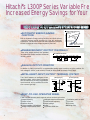 2
2
-
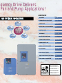 3
3
-
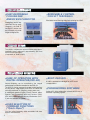 4
4
-
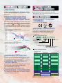 5
5
-
 6
6
-
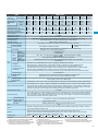 7
7
-
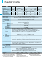 8
8
-
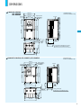 9
9
-
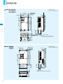 10
10
-
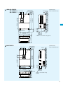 11
11
-
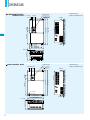 12
12
-
 13
13
-
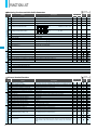 14
14
-
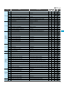 15
15
-
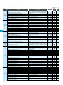 16
16
-
 17
17
-
 18
18
-
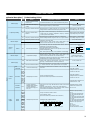 19
19
-
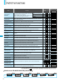 20
20
-
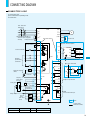 21
21
-
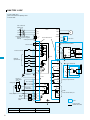 22
22
-
 23
23
-
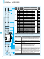 24
24
-
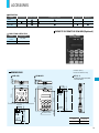 25
25
-
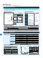 26
26
-
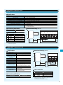 27
27
-
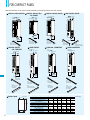 28
28
-
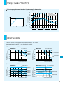 29
29
-
 30
30
-
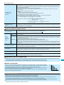 31
31
-
 32
32


Hitachi L300P User manual
- Category
- Power adapters & inverters
- Type
- User manual
- This manual is also suitable for
Ask a question and I''ll find the answer in the document
Finding information in a document is now easier with AI
Related papers
-
Hitachi L300P Series Quick Reference Manual
-
-
Hitachi L300P User manual
-
Hitachi L300P-185L User manual
-
-
-
-
-
-
Sabiana SJ700-2 Series User manual
Other documents
-
Makita HM1203C Datasheet
-
Makita HM1213C Datasheet
-
Makita HM1214C Datasheet
-
Makita HM1111C Datasheet
-
 StarTech.com PAC101Y Datasheet
-
ACP Speecon 7200M3 User manual
-
Baldor MN710 User manual
-
Mitsubishi Electric FR-FK REMOTE SPEED SETTER Owner's manual
-
-
Hyundai N700E 037 HF User manual
