Page is loading ...

ENGLISH
XL9
LCD PROJECTOR
MODEL
XL9U
User Manual
This User Manual is important to you.
Please read it before using your projector.
EN – 2
CAUTION
RISK OF ELECTRIC SHOCK
DO NOT OPEN
CAUTION: TO REDUCE THE RISK OF ELECTRIC SHOCK,
DO NOT REMOVE COVER (OR BACK)
NO USER-SERVICEABLE PARTS INSIDE
REFER SERVICING TO QUALIFIED
SERVICE PERSONNEL.
The lightning flash with arrowhead symbol within an equilateral triangle is intended to
alert the user to the presence of uninsulated “dangerous voltage” within the product’s
enclosure that may be of sufficient magnitude to constitute a risk of electric shock.
The exclamation point within an equilateral triangle is intended to alert the user to the
presence of important operating and maintenance (servicing) instructions in the litera-
ture accompanying the appliance.
WARNING:
TO PREVENT FIRE OR SHOCK HAZARD, DO NOT EXPOSE THIS APPLIANCE TO RAIN OR
MOISTURE.
CAUTION:
TO PREVENT ELECTRIC SHOCK, DO NOT USE THIS (POLARIZED) PLUG WITH AN EXTENSION
CORD, RECEPTACLE OR OTHER OUTLET UNLESS THE BLADES CAN BE FULLY INSERTED TO
PREVENT BLADE EXPOSURE.
NOTE:
SINCE THIS PROJECTOR IS PLUGGABLE EQUIPMENT, THE SOCKET-OUTLET SHALL BE
INSTALLED NEAR THE EQUIPMENT AND SHALL BE EASILY ACCESSIBLE.
WARNING
Use the attached specified power supply cord. If you
use another power-supply cord, it may cause
interference with radio and television reception.
Use the attached RGB cable or RS-232C cable with
this equipment so as to keep interference within the
limit of a FCC Class B device.
This apparatus must be grounded.
DO NOT LOOK DIRECTLY INTO THE LENS
WHEN THE PROJECTOR IS IN THE POWER
ON MODE.
CAUTION
Not for use in a computer room as defined in the
Standard for the Protection of Electronic Computer/
Data Processing Equipment, ANSI/NFPA 75.
The attached power cords are to be used exclusively
for this product. Never use them for other products.
When using the projector in Europe:
COMPLIANCE NOTICE
This Projector complies with the requirements of the
EC Directive 89/336/EEC “EMC Directive” as
amended by Directive 92/31/EEC and 93/68/EEC,
and 73/23/EEC “Low Voltage Directive” as amended
by Directive 93/68/EEC.
The electro-magnetic susceptibility has been chosen
at a level that gains proper operation in residential
areas, on business and light industrial premises and
on small-scale enterprises, inside as well as outside
of the buildings. All places of operation are
characterised by their connection to the public low
voltage power supply system.
WARNING
Use the attached RGB cable or RS-232C cable with
this equipment so as to keep interference within the
limits of an EN55022 Class B device.
Please follow WARNING instructions.

EN – 3
ENGLISH
Contents
Trademark, Registered trademark
Macintosh is registered trademark of Apple Computer Inc.
Other brand or product names are trademarks or registered trademarks of their respective holders.
Declaration of Conformity
Model Number : XL9U
Trade Name : MITSUBISHI ELECTRIC
Responsible party : Mitsubishi Digital Electronics America, Inc.
9351 Jeronimo Road, Irvine, CA 92618 U.S.A
Telephone number : +1-(949) 465-6000
This device complies with Part 15 of the FCC Rules. Operation is subject to the following two conditions:
(1) this device may not cause harmful interference, and
(2) this device must accept any interference received, including interference that may cause undesired
operation.
Important safeguards .......................................................................................... 4
Overview .............................................................................................................. 6
Remote control ..................................................................................................... 8
Installation ........................................................................................................... 9
Basic connections ............................................................................................... 10
Preparation ........................................................................................................ 12
Basic operation .................................................................................................. 13
Menu operation .................................................................................................. 15
Image adjustment .............................................................................................. 18
Advanced features ............................................................................................. 20
Lamp replacement ............................................................................................. 23
Maintenance ...................................................................................................... 24
Troubleshooting ................................................................................................. 25
Indicators ........................................................................................................... 28
Specifications ..................................................................................................... 29
Note: This symbol mark is for EU countries only.
This symbol mark is according to the directive 2002/96/EC Article 10 Information for
users and Annex IV.
Your MITSUBISHI ELECTRIC product is designed and manufactured with high quality materials and compo-
nents which can be recycled and reused.
This symbol means that electrical and electronic equipment, at their end-of-life, should be disposed of separately
from your household waste.
Please, dispose of this equipment at your local community waste collection/recycling centre.
In the European Union there are separate collection systems for used electrical and electronic product.
Please, help us to conserve the environment we live in!

EN – 4
Important safeguards
Please read all these instructions regarding your
LCD projector and retain them for future reference.
Follow all warnings and instructions marked on the
LCD projector.
1. Read instructions
All the safety and operating instructions should
be read before the appliance is operated.
2. Retain instructions
The safety and operating instructions should be
retained for future reference.
3. Warnings
All warnings on the appliance and in the
operating instructions should be adhered to.
4. Instructions
All operating instructions must be followed.
5. Cleaning
Unplug this projector from the wall outlet before
cleaning it. Do not use liquid aerosol cleaners.
Use a damp soft cloth for cleaning.
6. Attachments and equipment
Never add any attachments and/or equipment
without the approval of the manufacturer as
such additions may result in the risk of fire,
electric shock or other personal injury.
7. Water and moisture
Do not use this projector near water or in
contact with water.
8. Accessories
Do not place this projector on an unstable cart,
stand, tripod, bracket or table. Use only with a
cart, stand, tripod bracket, or table
recommended by the manufacturer or sold with
the projector. Any mounting of the appliance
should follow the manufacturer's instructions
and should use a mounting accessory
recommended by the manufacturer.
An appliance and cart combination should be
moved with care. Quick stops, excessive force
and uneven surfaces may cause the appliance
and cart combination to overturn.
9. Ventilation
Slots and openings in the cabinet are provided
for ventilation, ensuring reliable operation of the
projector and to protect it from overheating. Do
not block these openings or allow them to be
blocked by placing the projector on a bed, sofa,
rug, or bookcase. Ensure that there is adequate
ventilation and that the manufacturer's
instructions have been adhered to.
10. Power sources
This projector should be operated only from the
type of power source indicated on the marking
label. If you are not sure of the type of power,
please consult your appliance dealer or local
power company.
11. Power-cord protection
Power-supply cords should be routed so that
they are not likely to be walked on or pinched by
items placed upon or against them. Pay
particular attention to cords at plugs,
convenience receptacles, and points where they
exit from the appliance. Do not put the power
cord under a carpet.
12. Overloading
Do not overload wall outlets and extension cords
as this can result in a fire or electric shock.
13. Objects and liquids
Never push objects of any kind through openings
of this projector as they may touch dangerous
voltage points or short-out parts that could
result in a fire or electric shock. Never spill
liquid of any kind on the projector.
14. Servicing
Do not attempt to service this projector yourself.
Refer all servicing to qualified service personnel.
15. Damage requiring service
Unplug this projector from the wall outlet and
refer servicing to qualified service personnel
under the following conditions:
(a) If the power-supply cord or plug is damaged.
(b) If liquid has been spilled, or objects have
fallen into the projector.
(c) If the projector does not operate normally
after you follow the operating instructions.
Adjust only those controls that are covered
by the operating instructions. An improper
adjustment of other controls may result in
damage and may often require extensive
work by a qualified technician to restore the
projector to its normal operation.
(d) If the projector has been exposed to rain or
water.
(e) If the projector has been dropped or the
cabinet has been damaged.
(f) If the projector exhibits a distinct change in
performance - this indicates a need for
service.
16. Replacement parts
When replacement parts are required, be sure
that the service technician has used
replacement parts specified by the manufacturer
or parts having the same characteristics as the
original part. Unauthorized substitutions may
result in fire, electric shock or other hazards.
17. Safety check
Upon completion of any service or repair to this
projector, ask the service technician to perform
safety checks determining that the projector is
in a safe operating condition.

EN – 5
ENGLISH
COMPLIANCE NOTICE OF FCC
This equipment has been tested and found to comply with the limits for a Class B digital device, pursuant to
Part 15 of the FCC Rules. These limits are designed to provide reasonable protection against harmful
interference in a residential installation. This equipment generates, uses and can radiate radio frequency
energy and, if not installed and used in accordance with the instructions, may cause harmful interference to
radio communications. However, there is no guarantee that interference will not occur in a particular
installation. If this equipment does cause harmful interference to radio or television reception, which can be
determined by turning the equipment off and on, the user is encouraged to try to correct the interference by
one or more of the following measures:
• Reorient or relocate the receiving antenna.
• Increase the separation between the equipment and receiver.
• Connect the equipment into an outlet on a circuit different from that to which the receiver is connected.
• Consult the dealer or an experienced Radio / TV technician for help.
Changes or modifications not expressly approved by Mitsubishi could void the user's authority to operate this
equipment.
COMPLIANCE NOTICE OF INDUSTRY CANADA
This Class B digital apparatus complies with Canadian ICES-003.
WARNING:
Unplug immediately if there is something
wrong with your projector.
Do not operate if smoke, strange noise or odor comes out of
your projector. It may cause fire or electric shock. In this
case, unplug immediately and contact your dealer.
Never remove the cabinet.
This projector contains high voltage circuitry. An
inadvertent contact may result in an electric shock.
Except as specifically explained in User Manual, do
not attempt to service this product by yourself.
Please contact your dealer when you want to fix,
adjust, or inspect the projector.
Do not modify the projector.
It can lead to fire or electric shock.
Do not keep using the damaged projector.
If the projector is dropped and the cabinet is dam-
aged, unplug the projector and contact your dealer
for inspection. It may lead to fire if you keep using
the damaged projector.
Do not face the projection lens to the sun.
It can lead to fire.
Use correct voltage.
If you use incorrect voltage, it can lead to fire.
Do not place the projector on uneven surface.
Place the projector on a level and stable surface only.
Do not look into the lens when the projector is
operating.
It may hurt your eyes. Never let children look into
the lens when the projector is on.
Do not unplug the power cord during
operation.
It can lead to lamp breakage, fire, electric shock or
other trouble. Wait for the fan to stop before unplug-
ging the power cord.
Do not touch the air outlet grilles and bottom plate.
Do not touch them or put other equipment close to the air
outlet grilles because they become hot during operation.
The heated air outlet grilles and bottom plate may cause
injury or damage to other equipment. Also, do not put the
projector on a desk that is easily affected by heat.
Clean the air-filter once a month.
Clean the air-filter frequently. If the filter or ventila-
tion slots become clogged with dirt or dust, the
temperature inside of the projector may rise and
cause some troubles, such as damage of inside parts,
and shortening the life of the panels.
Do not look into the air outlet grilles when
projector is operating.
Heat, dust, etc. may blow out of them and hurt your eyes.
Do not block the air inlet and outlet grilles.
If they are blocked, heat may be generated inside the
projector, causing deterioration in the projector
quality and fire.
Do not use flammable solvents (benzene, thinner,
etc.) and flammable aerosols near the projector.
Flammable substances may ignite causing fire or
breakdown because the temperature inside the projector
rises very high while the lamp is illuminating.
Place of installation
For safety’s sake, do not use the projector at any
place subjected to high temperature and high hu-
midity. Please maintain an operating temperature,
humidity, and altitude as specified below.
• Operating temperature: between +41°F (+5°C)
and +95°F (+35°C).
•Operating humidity: between 30% and 90%.
•
Never put any heat-producing device under the projec-
tor to prevent the projector from being overheated.
•Do not install the projector at a place that is
unstable or subject to vibration.
• Do not install the projector near any equipment
that produces a strong magnetic field. Also re-
frain from installing the projector near any cable
carrying a large amount of current.
•Place the projector on a solid, vibration-free
surface. Otherwise it may fall, causing serious
injury or damage.
• Do not stand the projector on its end. It may fall,
causing serious injury or damage.
• Slanting the projector more than ±10˚(right and
left) or ±30˚(front and rear) may cause trouble or
explosion of the lamp.
• Do not place the projector near air-conditioning
unit or heater to avoid the air outlet and inlet
grilles from being exposed to hot air.
EN – 6
Overview
POWER STATUS
VIDEOKEYSTONE
ENTER
MENU
COMPUTER
AUTO POSITION
4
1
2
3
5
6
7
8
9
POWER STATUS
VIDEOKEYSTONE
ENTER
MENU
COMPUTER
AUTO POSITION
10
11
10
1
2 3 4 5
7 8 9
6
2
10
5431
9 8 67
11
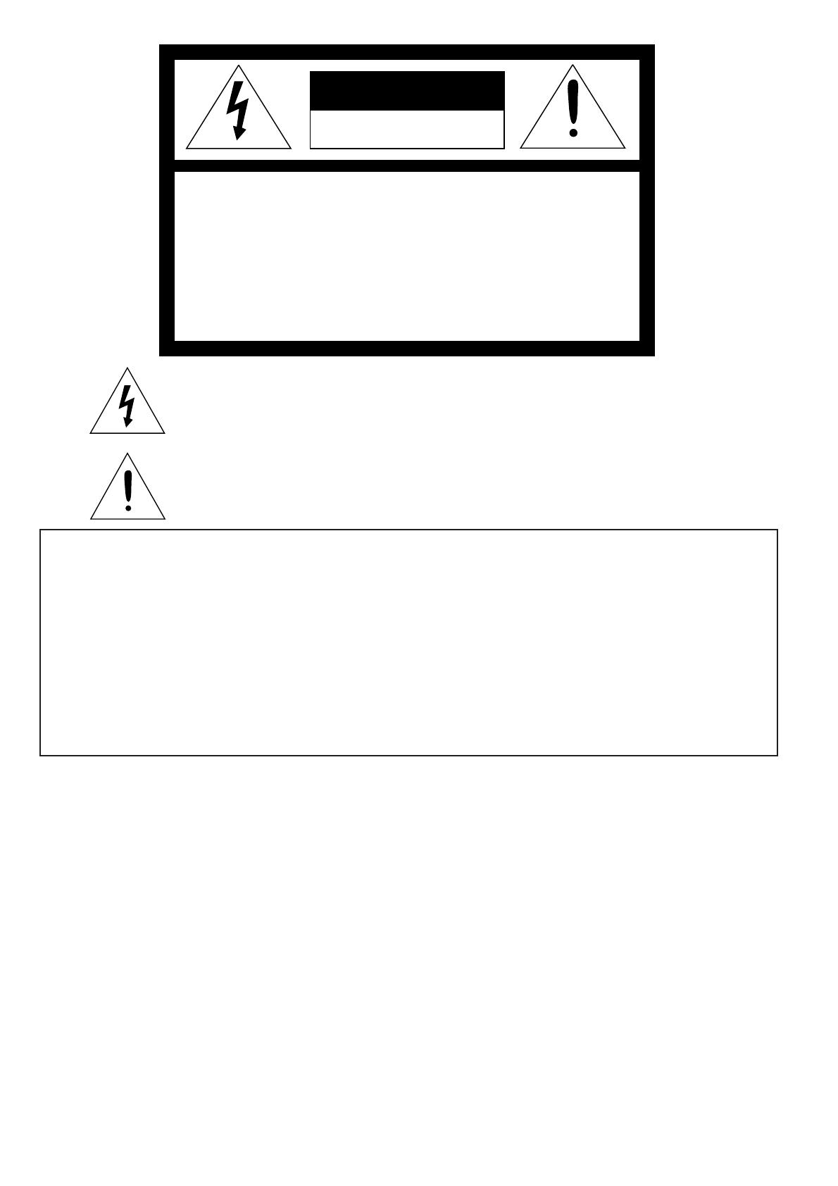
1 Remote control sensor (Front)
2 Control panel
3 Speaker
4Terminal panel
5 Air outlet grille
6 Kensington Security Lock Standard
connector
7 Foot adjustment button
8 Lens
9 Air outlet grille
10 Remote control sensor (Rear)
11 Air inlet grille
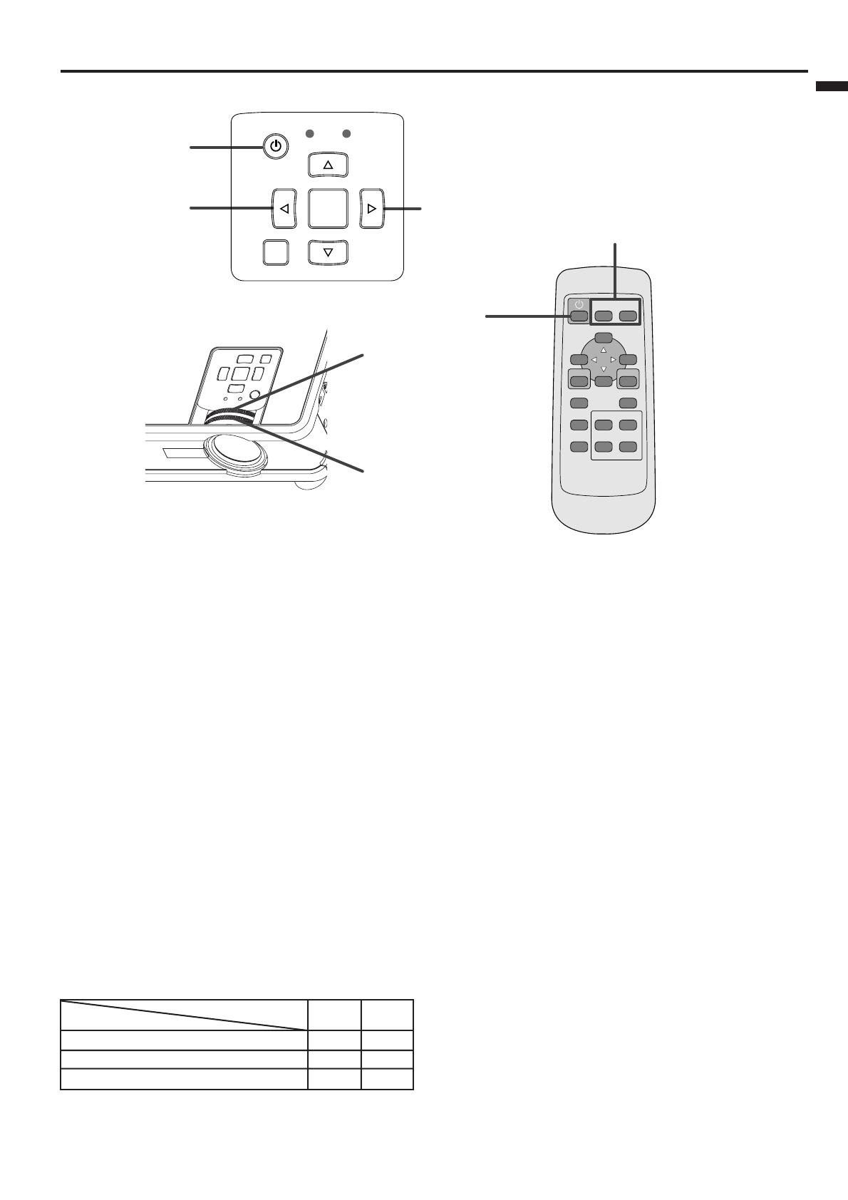
Control panel
1Focus ring
2Zoom ring
3 POWER indicator
4 POWER button
5 COMPUTER /
$$
$$
$ button
6 MENU button
7
}}
}}
} button
8 KEYSTONE/ENTER button
9 VIDEO /
%%
%%
% button
10 AUTO POSITION /
{{
{{
{ button
11 STATUS indicator
Important:
•While the menu or the screen for the keystone
adjustment is being displayed or image capturing is
being executed, the COMPUTER, VIDEO, and
AUTO POSITION buttons function as the $, %,
and { buttons respectively.
• While the menu is on the screen, the KEYSTONE
button functions as the ENTER button.
• While the screen for password entry is being
displayed, all buttons except the POWER button
will not function.
Terminal panel
1 USB terminal
2 SERIAL terminal (8P)
3 COMPUTER / COMPONENT VIDEO OUT
terminal (Mini D-SUB 15P)
4 COMPUTER / COMPONENT VIDEO IN-1
terminal (Mini D-SUB 15P)
5 COMPUTER / COMPONENT VIDEO IN-2
terminal (Mini D-SUB 15P)
6 Power terminal for wireless LAN unit (DC
OUT 5 V 1.5 A(MAX))
• Do not use the power terminal as a power for
other devices than the specified wireless LAN
unit. (Wireless LAN unit isn’t packaged together
with the projector.)
7 VIDEO IN terminals
8 AUDIO IN terminal
9 AUDIO OUT terminal
10 Power jack
Important:
• By connecting your computer to the USB terminal using an optional USB cable, you can use the mouse control
function of the computer with the optional remote control (R-SC1). (The provided remote control can't use the
function.) Ask your dealer for purchase of the optional remote control.
EN – 7
ENGLISH
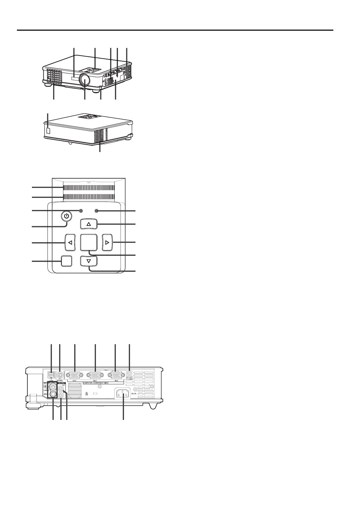
Bottom side
3
1
2
1
2
4
5
6
7
8
9
10
11
3
13
12
MENU ENTER
VIDEO
COMPUTER
16:9
STILL
EXPAND
VOLUME
KEYSTONE
-
+
MUTE
AUTO
POSITION
1 Lamp cover
2 Air inlet grille / Filter cover
3 Adjustment feet (Left/Right)
Caution:
Do not replace the lamp immediately after using the
projector because the lamp would be extremely hot and
it may cause burns.
Remote control
1 POWER button
2Direction buttons
3 MENU button
4 STILL button
5 AUTO POSITION button
6 MUTE button (Audio/Video)
7+ , - (VOLUME) buttons
8 EXPAND button
9 KEYSTONE button
10 16 : 9 button
11 ENTER button
12 COMPUTER button
13 VIDEO button
Important:
The + and - buttons are used in the keystone adjustment
and the EXPAND mode in addition to the volume control.
01
ENTER
32
645
978
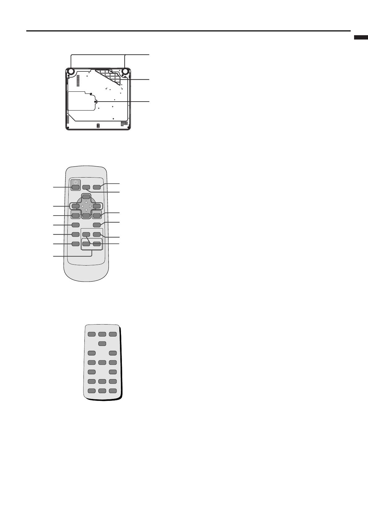
While the screen for password entry is being displayed, the buttons on the remote control will function as those
for password entry as shown below. (See page 22.)
• The POWER button on the remote control can be used for turning off the power.
EN – 8
Remote control
20˚
15˚
20˚
15˚
30˚30˚
20˚
20˚
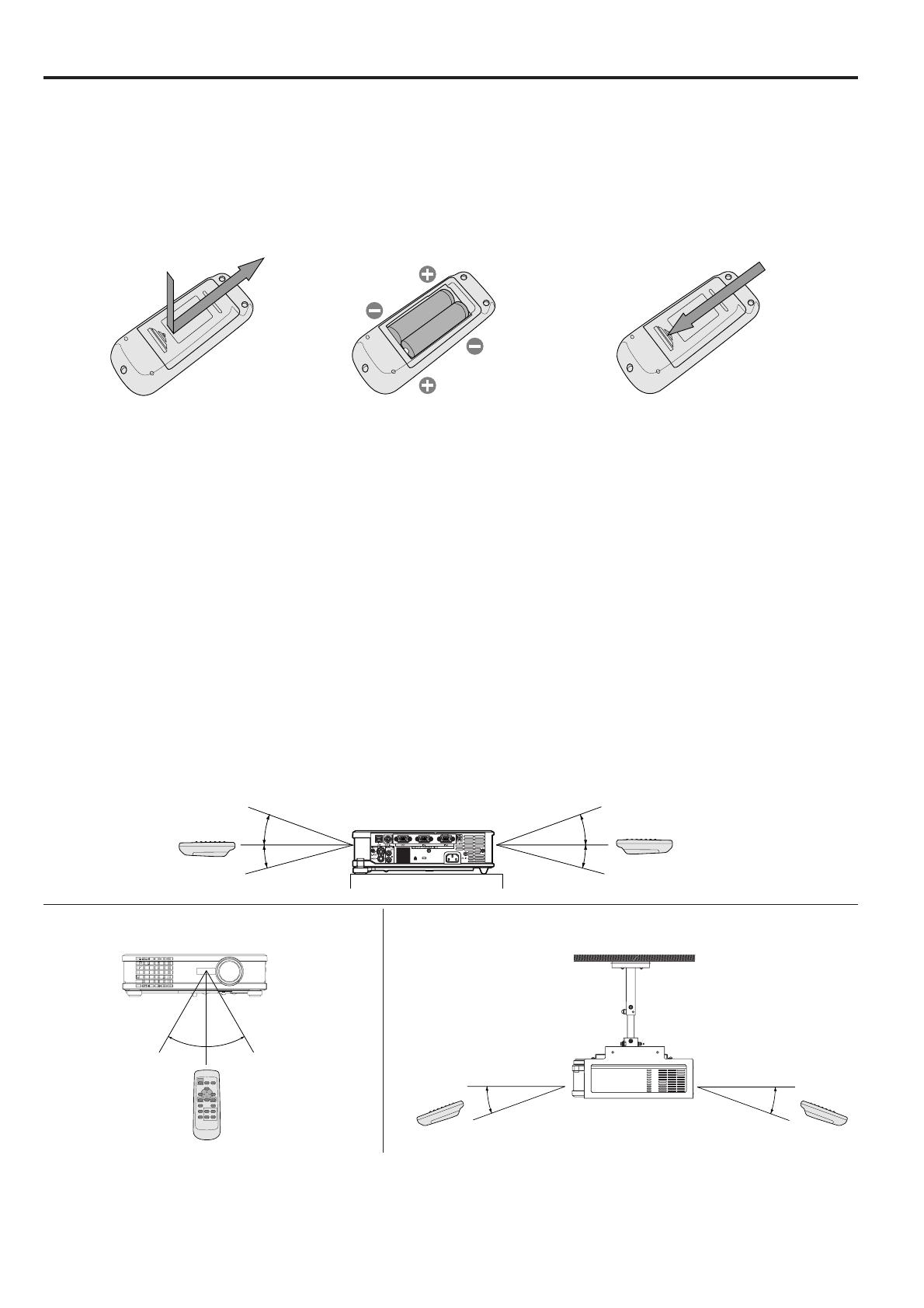
Battery installation
Use two AA size batteries.
1. Remove the back cover of the remote control by pushing the battery compartment door in the direction of the
arrow.
2. Load the batteries making sure that they are positioned correctly (+ to +, and - to -).
• Load the batteries from - spring side, and make sure to set them tightly.
3. Replace the back cover.
Caution:
• Use of a battery of wrong type may cause explosion.
• Only Carbon-Zinc or Alkaline-Manganese Dioxide type batteries should be used.
• Dispose of used batteries according to your local regulations.
• Batteries may explode if misused.
• Do not recharge, disassemble, or dispose of in fire.
• Be sure to handle batteries according to the instructions.
• Load batteries with the positive (+) and negative (-) sides correctly oriented as indicated on the remote control.
•Keep batteries out of reach of children and pets.
• Remove the batteries, if the remote control is not used for a long time.
• Do not combine a new battery with an old one.
• If the solution of batteries comes in contact with your skin or clothes, rinse with water. If the solution comes
in contact with your eyes, rinse them with water and then consult your doctor.
Operation range (of the remote control)
The maximum operation distance of the remote control is about 10 m (or about 32 feet) when the remote control
is pointed at the remote control sensor of the projector. When the remote control is pointed to the screen, the
distance from the remote control to the projector via the screen should be 6 m or less. However, the operation
distance varies depending on the type of the screen used.
Reception angle (vertical)
Reception angle (horizontal) Reception angle (vertical), ceiling mount
12 3
Important:
• Do not expose the remote control sensor to direct sunlight or fluorescent light. Keep a distance at least 2 m
(6.5 feet) between the remote control sensor and the fluorescent light to ensure correct operation of the remote
control. Inverted fluorescent light, if located near the projector, may interfere the remote control.
• When you use the remote control too close to the remote control sensor, the remote control may not work
correctly.

EN – 9
ENGLISH
Installation
Layout of the projector
Image size varies depending on the distance between the screen and the projector.
Front projection
Front projection, ceiling mounting
For ceiling mounting, you need the ceiling mount kit
designed for this projector. Ask a specialist for
installation. For details, consult your dealer.
• The warranty on this projector does not cover any
damage caused by use of any non-recommended
ceiling mount kit or installation of the ceiling
mount kit in an improper location.
• When using the projector mounted on the ceiling,
set IMAGE REVERSE in the INSTALLATION
menu to MIRROR INVERT. See page 16.
• When the projector is mounted on the ceiling,
images may appear darker than those projected in
the case of tabletop mounting. This isn’t a product
malfunction.
Rear projection
Ask a specialist for installation. For details, consult
your dealer.
•For rear projection, set IMAGE REVERSE in the
INSTALLATION menu to MIRROR. See page 16.
Caution:
• Placing the projector directly on a carpet impairs
ventilation by the fans, causing damage or failure.
Put a hard board under the projector to facilitate
ventilation.
• Place the projector at least 50 cm (or 20 inch)
away from the wall to prevent the air inlet grille
and the air outlet grilles that emit hot air from
being blocked.
• Do not use the projector in the following locations
and manners, which may cause fire or electric
shock.
• In a dusty or humid place.
•In a sideways or upside-down position.
• Near a heater.
• In an oily, smoky, or damp place such as a
kitchen.
• In direct sunlight.
• Where the temperature rises high, such as in a
closed car.
• Where the temperature is lower than +41°F (or
+5˚C) or higher than +95°F (or +35˚C).
W
A
A=B
B
H
Hd
L
• The above figures are approximate and may be slightly different from the actual measurements.
L: Distance between the screen and the front edge of the projector
Hd : Height of the projected image
Screen Distance from the screen : L
Diagonal size Width : W Height : H Maximum Minimum Hd
zoom (WIDE) zoom (TELE)
inch cm inch cm inch cm inch m inch m inch cm
40 102 32 81 24 61 47 1.2 56 1.4 2.2 5
60 152 48 122 36 91 71 1.8 85 2.2 3.2 8
80 203 64 163 48 122 95 2.4 114 2.9 4.3 11
100 254 80 203 60 152 119 3.0 143 3.6 5.4 14
150 381 120 305 90 229 178 4.5 215 5.5 8.1 21
200 508 160 406 120 305 238 6.0 287 7.3 10.8 27
250 635 200 508 150 381 298 7.6 359 9.1 13.5 34
300 762 240 610 180 457 358 9.1 – – 16.2 41
EN – 10
Basic connections
This projector can be connected with various devices such as a VCR, video camera, videodisc player, and personal
computer that have analog RGB output connectors.
Important:
• Make sure that the connected device is turned off before starting connection.
• Plug in the power cords of the projector and the connected devices firmly. When unplugging, hold and pull the
plug. Do not pull the cord.
• When the projector and the connected devices are located too close to each other, the projected image may be
affected by their interference.
• See the owner’s guide of each device for details about its connections.
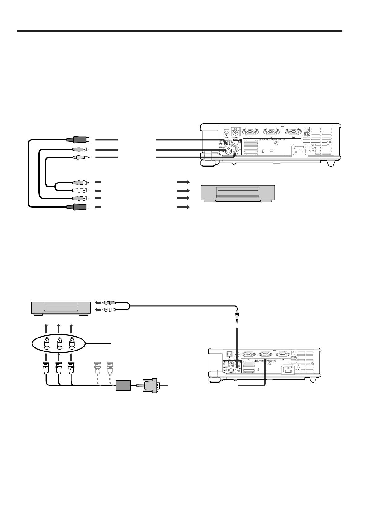
Projector + AV device
Important:
•Match the colors of the video and audio plugs on the AV cable with those of the terminals.
• Speaker output is mono.
• Set AUDIO MODE in the FEATURE menu to VIDEO to hear the audio only when the input source is VIDEO.
(See page 17.)
Projector + DVD player or HDTV decoder
Some DVD players have an output connector for 3-line fitting (Y, CB, CR). When connecting such DVD player with
this projector, use the COMPUTER/COMPONENT VIDEO IN terminal.
Important:
• The terminals’ names Y, PB, and PR are given as examples of when a HDTV decoder is connected.
• The terminals’ names vary depending on the connected devices.
• Use a Mini D-SUB 15P-BNC conversion cable for connection.
• Image may not be projected correctly with some DVD players.
•When connecting a HDTV decoder having RGB output terminals, set COMPUTER INPUT to RGB in the
SIGNAL menu.
• Speaker output is mono.
S-VIDEO IN
VIDEO IN
AUDIO IN
VCR, etc
to video output
to audio output
to S-video output
COMPUTER/COMPONENT
VIDEO IN
B G R
C
B
(P
B
)Y C
R
(P
R
)
HD/CS VD
AUDIO IN
DVD player or HDTV decoder
to audio output
AUDIO cable (option)
BNC-RCA connector (option)
No connection
Mini D-SUB 15P-BNC
conversion cable (optional)
EN – 11
ENGLISH
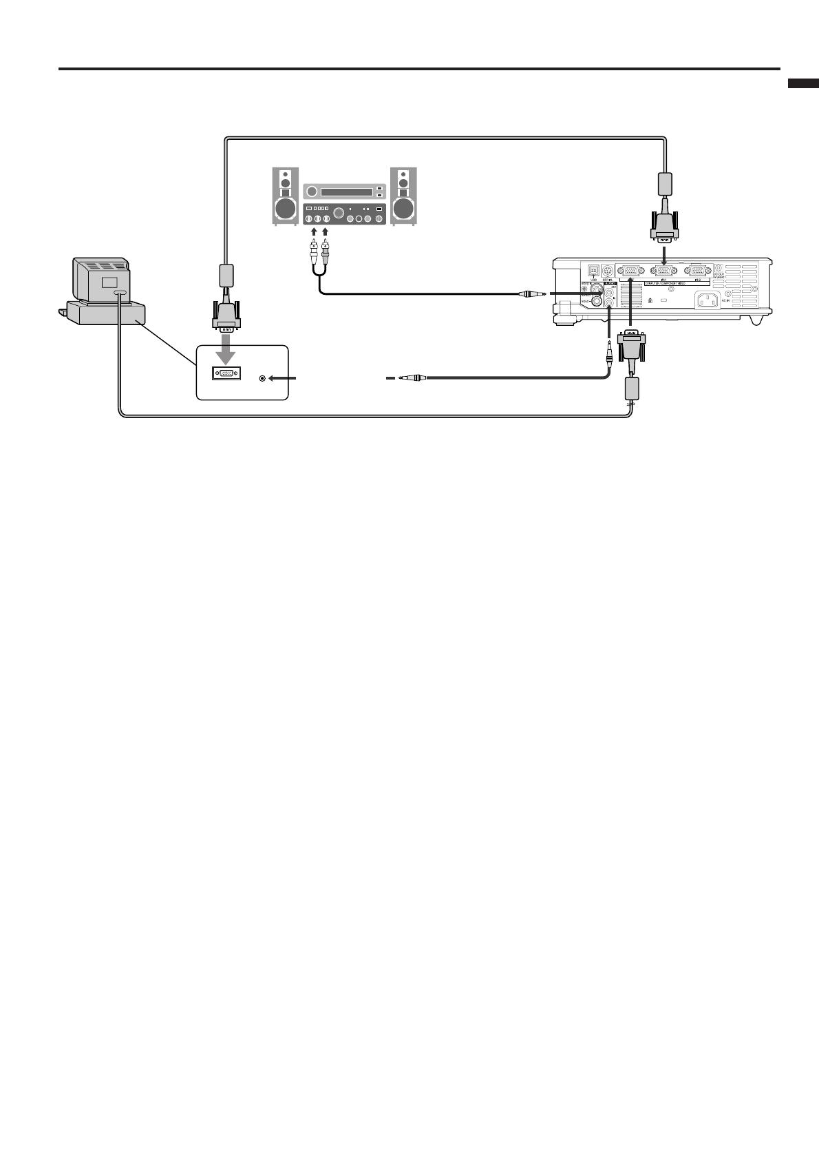
Projector + Computer
Important:
• When you use a longer RGB cable instead of the provided cable, the image quality may deteriorate.
• Some computers require additional connectors or analog RGB output adapters to be connected with this
projector. Contact your dealer for further information.
• This projector uses a stereo pin jack for its audio input. Check the type of the audio output terminal of the
connected computer and prepare a proper cable for connection. Some computers don’t have the audio output
terminal.
• Speaker output is mono.
• Set AUDIO MODE in the FEATURE menu to COMPUTER to hear the audio only when the input source is
COMPUTER. (See page 17.)
•When the audio cable is connected to the AUDIO OUT terminal, the speaker output is muted.
For Macintosh
• If your Macintosh has no video port, a monitor output adapter is required. Contact your dealer for further
information.
• Some Macintoshes require a MAC adapter for the RGB cable for connection with this projector. Contact your
dealer for further information.
About DDC
The COMPUTER/COMPONENT VIDEO IN-1 terminal of this projector complies with the DDC1/2B standard.
When a computer supporting this standard is connected to this terminal, the computer will automatically load
the information from this projector and prepare for output of appropriate images.
• After connecting a computer supporting this standard to this terminal, plug the power cord of the projector in
the wall outlet first, and then boot up the computer.
•You may need to install the DDC driver, depending on the computer you use. In this case, you need to
download the driver from our Web site. Contact your dealer or Mitsubishi sales office for further information.
AUDIO OUT
MONITOR OUTPUT
COMPUTER/COMPONENT
VIDEO IN
AUDIO IN
AUDIO OUT
COMPUTER/
COMPONENT
VIDEO OUT
RGB cable for PC
Computer
to monitor port
PC audio cable (option)
to PC audio
output
RGB cable for PC (option)
Necessary when outputting to both a PC monitor and the projector.
Audio cable (option)
to audio input

EN – 12
Preparation
Important:
• Install the screen on a flat wall at 90 degrees to the
floor.
• Slanting the projector more than ±10˚ (horizontally) or
±30˚ (vertically) may cause trouble or explosion of the
lamp. You can tilt the projector up to 7 degrees using
the adjustment feet only.
•Images may not be projected in a shape of a regular
rectangle or with its aspect ratio 4:3, depending on the
installation conditions of the projector and the screen.
•To correct vertical keystone distortion, press the
KEYSTONE button on the projector or the remote
control to display KEYSTONE, and adjust the image
by pressing the } or { button (or VOLUME + or -
button on the remote control).
In the following cases:
Preparation for projection
1. Attach the provided power cord to the projector.
2. Plug the power cord in the wall outlet.
3. Remove the lens cap.
Warning:
• Do not look into the lens directly when the projector is on.
• The lens cap is for protecting the lens. If you leave the
lens cap on the lens with the projector turned on, it
may be deformed because of heat build-up. Remove the
lens cap when you turn on the projector.
• The power cords for use in the U.S. and Europe are
provided with this projector. Use the appropriate cord
for your country.
•This projector uses the power plug of three-pin
grounding type. Do not remove the grounding pin from
the power plug. If the power plug doesn’t fit your wall
outlet, ask an electrician to change the wall outlet.
• The provided power cord for the U.S. is rated at 120 V.
Never connect this cord to any outlet or power supply
using other voltages or frequencies than rated. If you
want to use a power supply using other voltage than
rated, prepare an appropriate power cord separately.
• Use 100-240 V AC 50/60 Hz to prevent fire or electric
shock.
• Do not place any objects on the power cord or do not
place the projector near heat sources to prevent
damage to the power cord. If the power cord should be
damaged, contact your dealer for replacement because
it may cause fire or electric shock.
• Do not modify or alter the power cord. If the power
cord is modified or altered, it may cause fire or electric
shock.
Caution:
• Plug in the power cord firmly. When unplugging, hold
and pull the power plug, not the power cord.
• Do not plug in or out the power cord with your hand
wet. It may cause electric shock.
Adjustment of the projection angle
For the best projection, project images on a flat screen
installed at 90 degrees to the floor. If necessary, tilt the
projector using the two adjustment feet on the bottom of
the projector.
1. Tilt up the project to the appropriate angle.
2. Press the foot adjustment buttons next to the
adjustment feet, and the adjustment feet will come
out.
3. Release the buttons to lock the adjustment feet to that
position.
4. Rotate the adjustment feet for fine adjustment.
After using the projector:
5. Put the adjustment feet back into the projector by
pressing the foot adjustment buttons.
Important:
• When the keystone adjustment is carried out, the
adjustment value is indicated. Note that this value
doesn’t mean a projection angle.
• The allowable range of the adjustment value in the
keystone adjustment varies depending on the
installation conditions.
• When the keystone adjustment takes effect, the
resolution decreases. In addition, stripes may appear or
straight lines may bend in images with complicated
patterns. They are not due to product malfunctions.
• Noise may appear on the screen during the keystone
adjustment because of the type of the video signal being
projected and the setting values of the keystone
adjustment. In such cases, set the keystone adjustment
values in the range where the image is displayed
without noise.
•When the keystone adjustment is carried out, the
image may not be displayed correctly because of
the type of input signal.
• When the 1080i signal is input, the keystone
adjustment ranges are limited.
Screen
Adjustment feet
Press the }
(or -) button.
Press the {
(or +) button.
EN – 13
ENGLISH
Basic operation
Important:
• The projector starts warming up when the
POWER button is pressed. During the warm-up
process, images may appear dark and no
commands are accepted.
• By blinking red, the STATUS indicator indicates
that the lamp should be replaced soon. Replace
the lamp when the STATUS indicator blinks red.
(See page 28.)
• Images may not be projected with good quality in
an extremely hot or cold environment. (This is not
a product malfunction.)
4. Adjust the focus by turning the focus ring.
5. Choose your desired external input source using
the COMPUTER or VIDEO button.
• The input source is switched between
COMPUTER1 and COMPUTER2 at every
press of the COMPUTER button.
• The input source is switched between VIDEO
and S-VIDEO at every press of the VIDEO
button.
•The projector automatically selects the
appropriate signal format. The selected signal
format is displayed on the screen.
• The COMPUTER and VIDEO buttons don’t
function while the menu is being displayed.
•Images supplied from the computer may
flicker. Press the $ or % button on the remote
control to reduce flicker, if it occurs.
6. Adjust the image size by turning the zoom ring.
• If necessary, adjust the focus and zoom again.
Power-on
1. Turn on the device connected to the projector first.
2. Plug the power cord in the wall outlet.
• The POWER indicator lights up.
• If the power cord is unplugged from the wall
outlet before the projector is cooled down
completely after use, the fans may start
rotating when the power cord is plugged in
next time and the POWER button may not
function. In this case, wait for the fans to stop
and press the POWER button to light the
indicator.
3. Press the POWER button.
• It may take about 1 minute for the lamp to
light up.
•The lamp occasionally fails to light up. Wait a
few minutes and try to light the lamp again.
• After the POWER button is pressed or the
lamp mode is switched, the image may flicker
before the lamp becomes stable. This is not a
product malfunction.
• The STANDARD lamp mode is activated by
default whenever the projector is turned on.
When the LOW lamp mode has been chosen,
the default STANDARD lamp mode is switched
to the LOW lamp mode in 1.5 minutes.
Condition
Indicator
STATUS
POWER
-
Stand-by
Red
MENU ENTER
VIDEO
COMPUTER
16:9
STILL
EXPAND
VOLUME
KEYSTONE
-
+
MUTE
AUTO
POSITION
55
3,
1
,
2
POWER STATUS
VIDEOKEYSTONE
ENTER
MENU
COMPUTER
AUTO POSITION
5
3,
1
,
2
When the lamp is on.
Green Green
6
4
When the lamp is off temporarily.
-
Red

EN – 14
VOLUME 15
Volume from the speaker
Press the VOLUME + or – button to change the
volume from the speaker.
The volume control bar will appear on the screen.
• The volume control bar will disappear about 10
seconds after the VOLUME button is released.
• The VOLUME buttons don’t function while the
menu selection bar or the menu is being
displayed.
• When a high-level audio signal, such as a DVD
audio signal, is supplied to the AUDIO IN
terminal, the output from the speaker may be
distorted.
AV mute
The video and audio signals are temporarily muted
when the MUTE button is pressed. To cancel muting,
press the MUTE button again.
• If MUTE MODE in the INSTALLATION menu is
set to IMAGE, the splash screen will appear when
the MUTE button is pressed.
•You can alter the splash screen optionally. See
page 21.
• When muting starts, the lamp mode becomes
LOW, darkening the displayed image. This is not a
product malfunction.
ANAMORPHIC mode
When playing DVD discs containing data of
letterboxed image, press the 16:9 button. Exit the
ANAMORPHIC mode by pressing the 16:9 button
again.
Caution:
• After using the projector, wait 1 minute for the air
outlet fans to stop. Then unplug the power cord
from the wall outlet.
•The lamp can’t be lit again for 1 minute after
turned off for safety purpose. It will take another
1 minute for the STATUS indicator to go out. If
you want to turn on the projector again, wait until
the indicator goes out, and then press the POWER
button.
• The air outlet fans rotate faster as the
temperature around the projector rises.
• When the temperature around the projector rises
high, the sign “TEMPERATURE!!” blinks red on
the screen. If the temperature stays high, the
lamp will go out automatically.
Power-off
Use the following procedure to turn off the projector.
Do not turn off the projector by unplugging the power
cord while the lamp is on. Unplugging while the lamp
is on degrades the lamp’s performance and causes
failure in the projector.
11. Press the POWER button.
• The message “POWER OFF? YES : PRESS
AGAIN” appears on the screen.
•To cancel, press any button except the POWER
button. (Some buttons on the remote control
don’t function for cancel.)
22.Press the POWER button within 10 seconds again.
• The lamp will go out and the STATUS
indicator will start blinking.
• Though the lamp goes out at this second press
of the POWER button, the air outlet fans
continue operating for one minute to cool down
the lamp and LCD panels. The STATUS
indicator will stop blinking.
33. Unplug the power cord.
• The POWER indicator will go out.
• If the power cord should be unplugged
accidentally while either the air inlet fan or the
air outlet fans are operating or the lamp is on,
allow the projector to cool down for 10 minutes
with the power off. To light the lamp again,
press the POWER button. If the lamp doesn’t
light up immediately, repeat pressing the
POWER button two or three times. If it should
still fail to light up, replace the lamp.
Important:
• When storing the projector in the provided
carrying case, the lens should face up.
AUTO POSITION button
When the image isn’t projected in the right position
with COMPUTER selected as the input source, follow
the procedure below.
1. Project a bright image such as the “Recycle Bin”
window on the full screen.
2. If the screen saver is running, turn it off.
3. Press the AUTO POSITION button.
• If the image is still not in the right position,
adjust the image position using the SIGNAL
menu.
Basic operation (continued)

EN – 15
ENGLISH
Menu operation
IMAGE
XGA60
opt.
INSTALLATION
opt.
XGA60
INSTALLATION
opt.
AUTO POWER
ON
AUTO POWER
OFF
OFF
OFF
XGA60
AUTO POWER
ON
AUTO POWER
OFF
OFF
OFF
AUTO POWER
ON
AUTO POWER
OFF
30 min
OFF
Basic operation
Several settings can be adjusted using the menu.
Example: Auto power off time setting
1. Press the MENU button.
2. Press the $ or % button to select
INSTALLATION.
3. Press the ENTER button (or } button).
4. Press the { or } button to select AUTO
POWER OFF.
5. Press the $ or % button to adjust the auto
power off time.
6. Exit the menu by pressing the MENU button
several times.
Important:
• When the MENU button doesn’t function,
unplug the power cord from the wall outlet.
Wait about 10 minutes, plug the power cord in,
and try again.
• After selecting the items marked with , press
the ENTER button.
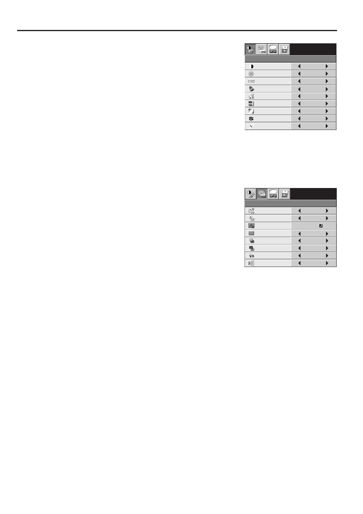
IMAGE CONTRAST ± 30
BRIGHTNESS
COLOR MATRIX
± 30
sRGB ON , OFF
STANDARD
LOW
HIGH
USER
COLOR TEMP.
COLOR ± 10
TINT ± 10
SHARPNESS ± 5
GAMMA MODE AUTO, DYNAMIC, STANDARD, THEATER
CONTRAST R ± 30
CONTRAST B ± 30
BRIGHTNESS R ± 30
BRIGHTNESS B ± 30
EXPAND MODE
EXPAND, REAL
AUDIO MODE COMPUTER, VIDEO, COMPUTER VIDEO, MUTE
INSTALLATION
OFF, MIRROR, INVERT, MIRROR INVERT
AUTO POWER ON
ON , OFF
RESET ALL OK
AUTO POWER OFF
ON , OFF
FEATURE MENU POSITION 1 (Upper left), 2(Lower right)
IMAGE REVERSE
SPLASH SCREEN
BLACK, IMAGEMUTE MODE
BLUE, BLACK, IMAGEBACK COLOR
STANDARD, LOWLAMP MODE
OFF, CENTER, UPPER, LOWER ANAMORPHIC
DISPLAY INPUT , MENU ACCESS , SPLASH ID SCREEN
PASSWORD FUNCTION
ON , OFFSCART INPUT
VIDEO SIGNAL AUTO , NTSC , PAL , SECAM , 4.43NTSC , PAL-M , PAL-N , PAL-60
LANGUAGE
, English, Español, Deutsch, Français, Italiano, , , ,
VIDEO
YELLOW ± 30
RED ± 30
BLUE ± 30
CYAN ± 30
GREEN ± 30
MAGENTA ± 30
RGB-TINT ± 20
COMPUTER
USER
OFF
SIGNAL
HORIZ.POSITION
HOLD
0 - 999
VERT.POSITION 0 - 999
FINE SYNC. 0 - 31
TRACKING
USER
0 - 9999
CLAMP POSITION
0 - 63
CLAMP WIDTH 1 - 63
SHUTTER (L)
0 - 20
SHUTTER (U)
0 - 20
SHUTTER (RS)
0 - 20
SHUTTER (LS)
0 - 20
VERT. SYNC.
AUTO, OFF
*5
*3
*3
AUTO , OFFCINEMA MODE
*3
*3*3
*3
*3
*3
*5
*5
ON
BEGIN 0 - 15
END 0 - 15
OFF
COMPUTER INPUT
RGB, YCBCR / YPBPR
*5
*5
OFF, 5, 10, 15, 30, 60 min
OK
OK
UNLOCK OK
LOCK
*1
*1
*1
*2*1
*1
*3
*4
*2
IMAGE CAPTURE
SETUP
x1, x2, FULL
GLAY, RED, GREEN, BLUE, BLACK, WHITE, RED 50%, GREEN 50%, BLUE 50%
CAPTURE
BACK COLOR
SIZE
GO
(Displayed only when the source is VIDEO or S-VIDEO.)
(Displayed only when the source is VIDEO or S-VIDEO.)
(These items are not available when the input
source is COMPUTER.)
* 1: Not available when sRGB is set to ON.
* 2: Not available with certain signals.
* 3: Not available when the source is a VIDEO
or S-VIDEO signal.
* 4: Available only when the input signal is TV60 or 480i.
* 5: Setting range differs depending on the input signals.
EN – 16
Menu operation (continued)
INSTALLATION
opt.
ON
BACK COLOR
AUTO POWER
ON
AUTO POWER
OFF
SPLASH
SCREEN
MUTE MODE
LAMP MODE
ON
BLUE
BLACK
OFF
IMAGE
CAPTURE
SETUP
OFF
STANDARD
OFF
IMAGE
REVERSE
XGA60
CONTRAST
IMAGE
0
BRIGHTNESS 0
STANDARD
0
COLOR
AUTO
0
XGA60
COMPUTER
OFF
TINT
0SHARPNESS
COLOR TEMP.
GAMMA MODE
COLOR MATRIX
sRGB
opt.
1 IMAGE
CONTRAST ......... Use to adjust the image contrast. The contrast becomes higher
as the value increases.
BRIGHTNESS ..... Use to adjust the image brightness. The image becomes
brighter as the value increases.
sRGB .................... Choose ON for projection emphasizing on the color
reproducibility.
• When sRGB is ON, COLOR MATRIX, COLOR TEMP.,
COLOR, TINT, and GAMMA MODE can't be adjusted.
COLOR MATRIX . Use to adjust the color balance in each color of the image. See
page 18.
COLOR TEMP. .... Use to adjust the color temperature. See page 18.
COLOR ................ Use to adjust the color intensity of the image.
TINT .................... Use to adjust the color balance of the image. The color balance
shifts to green as the value increases and shifts to purple as
the value decreases. (Available only when VIDEO is chosen as
the source.)
• When the TV50 (PAL, SECAM) signal is input, TINT can't be adjusted.
SHARPNESS ....... Use to adjust the image sharpness. The image becomes sharp as the value increases. (Available only
when VIDEO is chosen as the source.)
GAMMA MODE ... When AUTO is selected, the appropriate gamma mode is automatically selected depending on the
input signal. For normal use, select AUTO. Select DYNAMIC for computer sources. Select
STANDARD for sport scenes and video sources. Select THEATER for film sources.
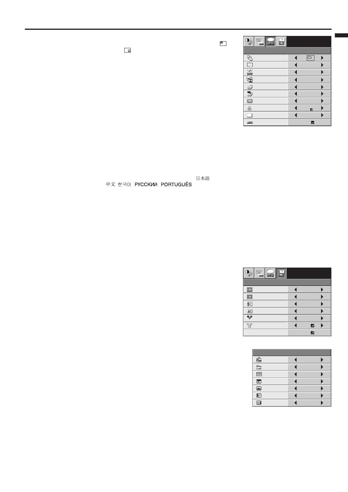
2 INSTALLATION
AUTO POWER ON ..
When ON is chosen, the lamp is automatically lit when the
power cord is plugged in the wall outlet. Choose ON when
using the projector mounted on the ceiling.
• The projector is in the stand-by mode when the lamp
is off. Use the remote control to turn on the lamp.
AUTO POWER OFF ..
Use to set the time elapsed before the projector enters the
stand-by mode when there is no signal input from the source.
IMAGE CAPTURE ..
Use to capture the screen for the splash screen. See page 21.
SPLASH SCREEN ..
Choose ON to display the splash screen when the power
is turned on.
• The splash screen can be changed. See page 21.
BACK COLOR .... Use to select the background from among BLUE, BLACK and
IMAGE, which will be displayed when there is no signal input from the source. When IMAGE is
selected, the splash screen will be displayed.
MUTE MODE ..... Use to choose the background, either BLACK, or IMAGE, which will be displayed when the MUTE
button is pressed. When IMAGE is chosen, the splash screen will be displayed.
LAMP MODE...... Use to change the brightness of the lamp. When LOW is chosen, the lamp brightness is kept low
and the volume of the operation sound is reduced, resulting in a longer lamp replacement interval.
• The STANDARD lamp mode is activated by default whenever the projector is turned on.
When the LOW lamp mode has been chosen, the default STANDARD lamp mode is
switched to the LOW lamp mode in 1.5 minutes.
• When the lamp mode is switched, the projected image may flicker. This is not a product
malfunction.
IMAGE REVERSE ..
Use to reverse the projected image. Select MIRROR for rear projection with the tabletop-mounted
projector. Select MIRROR INVERT for front projection with the ceiling-mounted projector.
• When you continue projection for a long time with BACK COLOR or MUTE MODE set to IMAGE, an after-
image may persist on the screen.
• Do not change the setting of LAMP MODE frequently.
•You can’t set IMAGE CAPTURE or SPLASH SCREEN when PASSWORD FUNCTION in the FEATURE
menu has been set to SPLASH ID SCREEN to enable the password lock.
EN – 17
ENGLISH
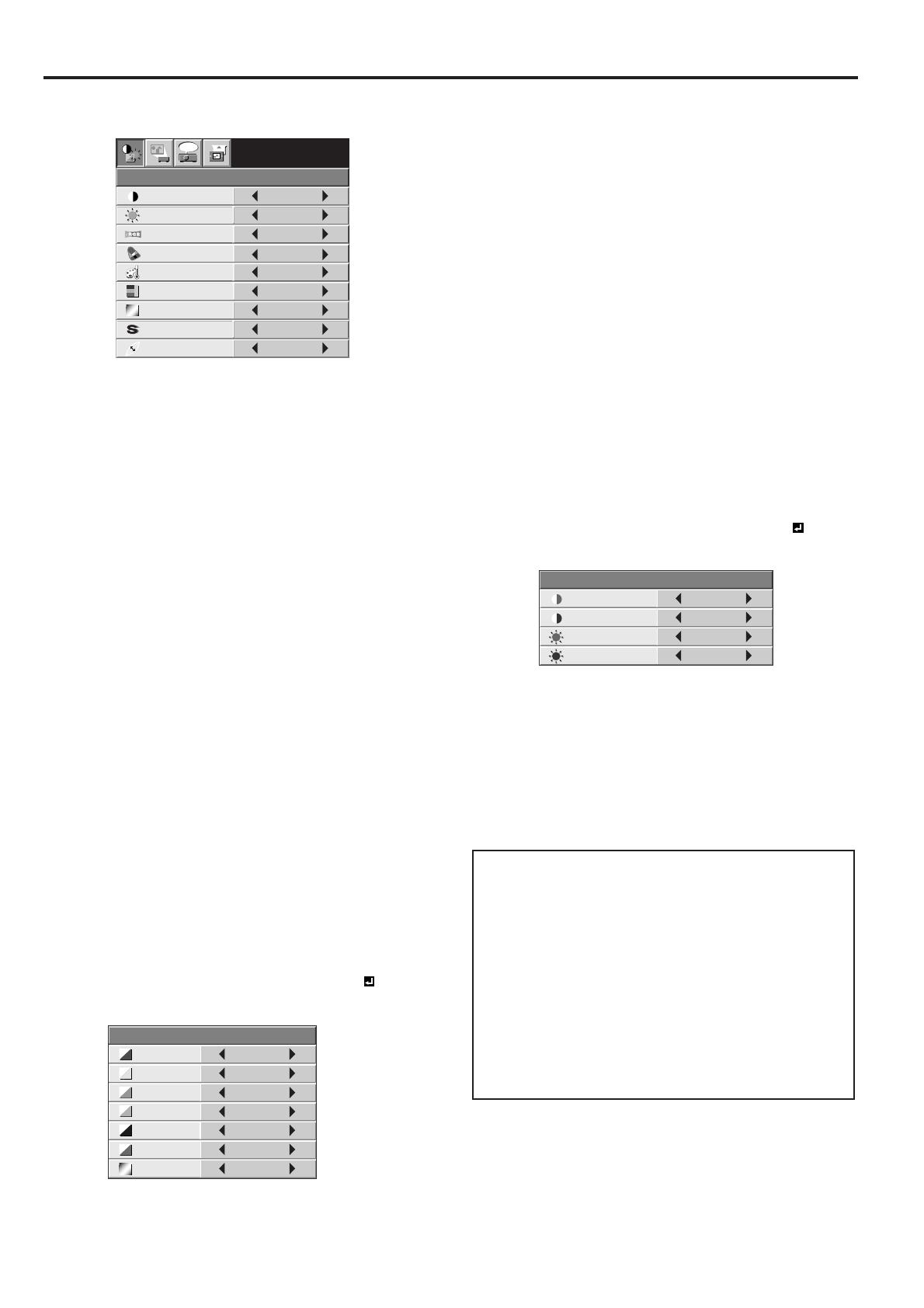
3 FEATURE
MENU POSITION ...
Use to select the position of the menu on the screen, 1.
(upper left) or 2. (lower right).
EXPAND MODE .. Choose the mode for enlarging the image. See page 20.
AUDIO MODE ..... Select COMPUTER to output the audio that is input to the
AUDIO IN terminal when COMPUTER is chosen as the
source. Select VIDEO to output the audio that is input to that
terminal when VIDEO is chosen as the source. Select
COMPUTER VIDEO mode to always output the audio that is
input to that terminal. Select MUTE not to output the audio at
all.
CINEMA MODE .. When AUTO is selected, the film mode will be automatically
activated when a film source signal is input. When OFF is
selected, the film mode will not be activated.
VIDEO SIGNAL ... When AUTO is selected, the appropriate video format is
automatically selected depending on the input signal. If the
image isn’t displayed correctly, select the desired video format manually.
SCART INPUT ..... Choose ON when connecting the projector with a device equipped with the SCART terminal that
can output RGB signal. SCART terminal is used mainly in Europe. Choose OFF normally.
ANAMORPHIC .... Select the desired position from among UPPER, CENTER, and LOWER when playing DVD discs
containing data of letterboxed images.
PASSWORD FUNCTION .
Use to change the mode of the password lock or to enable or cancel the password lock. See page 22
for details.
LANGUAGE ........ Use to select the language used in the menu. ( / English / Español / Deutsch / Français /
Italiano / / / / )
RESET ALL ......... Use to reset the menu settings (except IMAGE CAPTURE, PASSWORD, and LANGUAGE ).
• CINEMA MODE can be adjusted only when a TV60 or 480i signal is being displayed.
• When SCART INPUT is set to ON, nothing is output to the external monitor.
•When SCART INPUT is set to ON, normal computer signals aren’t projected.
• Use a SCART-BNC (or SCART-Mini D-SUB 15P) cable (option) when connecting this projector with an AV
device equipped with the SCART terminal.
• Some AV devices equipped with the SCART terminal aren’t compatible with this projector.
•When VIDEO SIGNAL is set to AUTO, the image may not be projected with correct colors. Change the
setting of VIDEO SIGNAL depending on the input signal in such cases.
• When ANAMORPHIC is set to except OFF, the keystone adjustment ranges are limited.
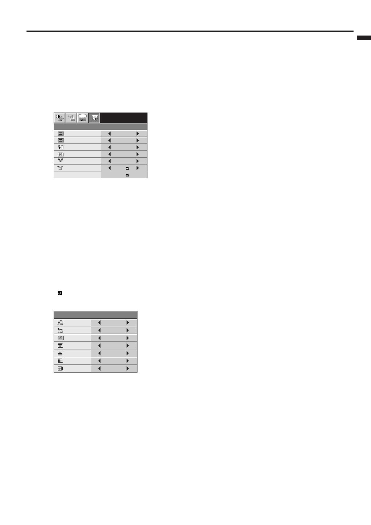
4 SIGNAL
HORIZ. POSITION ...
Use to adjust the horizontal position of the image.
VERT. POSITION ...
Use to adjust the vertical position of the image.
FINE SYNC. ......... Use to synchronize the projector with the PC input signal so
that the image is not blurred.
TRACKING .......... Use to eliminate image noise such as wide stripes.
COMPUTER INPUT ...
The projector adjusts its settings automatically when
connected to a DVD player equipped with a component video
output (Y, CB, CR). When the projector is connected with a
device having an RGB terminal, choose RGB manually.
HOLD .................. Use to adjust the image when flagging occurs near the top of
the screen.
5 SIGNAL - USER (No need to adjust in normal use.)
CLAMP POSITION/
CLAMP WIDTH ... Use to correct solid white or solid black in the projected image.
VERT.SYNC. ........ Use to adjust the image when its motion doesn’t run smoothly.
Select AUTO for normal use.
SHUTTER (U) ...... Use to adjust the image when noise appears on the top part of the
image.
SHUTTER (L) ...... Use to adjust the image when noise appears on the bottom part of
the image.
SHUTTER (LS) .... Use to adjust the image when noise appears on the left half of the
image.
SHUTTER (RS) .... Use to adjust the image when noise appears on the right half of
the image.
• If any setting of the SIGNAL-USER menu is changed, the image may not be displayed correctly. In this
case, press the AUTO POSITION button.
Important:
•You can set the IMAGE, SIGNAL, and SIGNAL-USER menus only when the signal is supplied.
• TV60 and TV50 are equivalent to 480i and 576i respectively. Settings made for one of them apply
automatically when its counterpart is supplied.
FEATURE
OFF
OFF
XGA60
AUTO
EXPAND
opt.
MENU POSITION
EXPAND MODE
A
A
VIDEO SIGNAL
?
ANAMORPHIC
RESET ALL
English
LANGUAGE
A
Ë
OK
SCART INPUT
DISPLAY
INPUT
PASSWORD
FUNCTION
CINEMA MODE
AUTO
AUDIO MODE
COMPUTER
VIDEO
1.
CLAMP
POSITION
SIGNAL-USER
0
CLAMP WIDTH 1
SHUTTER (U) 0
SHUTTER (L) 0
SHUTTER (LS) 0
SHUTTER (RS) 0
VERT. SYNC. AUTO
?
R G B
R G B
SIGNAL
HORIZ. POSITION 0
VERT. POSITION 0
TRACKING 0
COMPUTER
INPUT
RGB
FINE SYNC. 0
USER
XGA60
opt.
OK
ON
HOLD
EN – 18
Image adjustment
CONTRAST R
COLOR TEMP.-USER
0
CONTRAST B 0
BRIGHTNESS R 0
BRIGHTNESS B 0
CONTRAST
IMAGE
0
BRIGHTNESS 0
STANDARD
0
COLOR
AUTO
0
XGA60
COMPUTER
OFF
TINT
0SHARPNESS
COLOR TEMP.
GAMMA MODE
COLOR MATRIX
sRGB
opt.
4. Press the { or } button to select the desired
color.
• If you want to adjust the balance of all colors of
the image, select RGB-TINT.
5. Press the $ or % button to adjust the color
balance of the selected color.
6. Repeat steps 4 and 5 for optimum adjustment
results.
7. Exit the menu by pressing the MENU button
several times.
• When the input source is VIDEO or COMPUTER,
the setting items in the color matrix adjustment
are automatically set to the predetermined values.
You can change these settings manually.
•To cancel the color matrix adjustment, select OFF
in step 2.
• When the color matrix adjustment is carried out,
the colors in the menu will also vary. This isn’t a
product malfunction.
Color temperature
1. Select COLOR TEMP. in the IMAGE menu.
2. Press the $ or % button to select USER .
3. Press the ENTER button.
4. Press the { or } button to select the desired
item.
5. Press the $ or % button to adjust the selected
item.
6. Repeat steps 4 and 5 for optimum adjustment
results.
7. Exit the menu by pressing the MENU button
several times.
COLOR MATRIX
0
0
0
0
0
0
0
RED
RGB-TINT
GREEN
BLUE
YELLOW
CYAN
MAGENTA
About color temperature
There are different kinds of white color. Color
temperature is a way to show the differences in
white. White of which temperature is low appears
reddish. When the color temperature rises, white
appears bluish. This projector adjusts this color
temperature by changing the values of contrast
blue and red.
To rise the color temperature:
Increase the CONTRAST B (blue) and decrease the
CONTRAST R (red).
To reduce the color temperature:
Decrease the CONTRAST B (blue) and increase
the CONTRAST R (red).
Image adjustment
You can adjust the image using the IMAGE menu.
To control the white-to-black level of the image :
Adjust CONTRAST in the IMAGE menu. Press the
% button to increase the contrast and the $ button
to reduce it.
To control the light level of the image :
Adjust BRIGHTNESS in the IMAGE menu. Press
the % button to lighten the image and the $ button
to darken it.
To determine the intensity of the color :
Adjust COLOR in the IMAGE menu. Press the %
button to increase the intencity of color in the image
and the $ button to decrease it.
To adjust the red-green color balance of the
image :
Adjust TINT in the IMAGE menu. Press the %
button to increase the amount of green in the image
and the $ button to increase the amount of red in
the image.
To adjust the detail and clarity of the image :
Adjust SHARPNESS in the IMAGE menu. Press the
% button to sharpen the image and the $ button to
soften the image.
Color matrix
This projector adjusts the color balance in each color
of RGB (red, green, and blue) and their neutral colors
(yellow, cyan, and magenta) by the color correction
adjustment. Use the color correct adjustment when
you want to emphasize color or when only a certain
color balance is not correctly adjusted.
1. Select COLOR MATRIX in the IMAGE menu.
2. Press the $ or % button to select USER .
3. Press the ENTER button.
EN – 19
ENGLISH
Adjustment of the image from the
computer
This projector adjusts the format of the video signal
supplied from the computer. However, sometimes
images are not projected correctly owing to the type
of the computer used. When the image from the
computer isn’t projected correctly, press the AUTO
POSITION button. (See page 14.) If the image isn’t
projected correctly yet, adjust the image from the
computer using the menu.
To move the image horizontally :
Adjust HORIZ. POSITION in the SIGNAL menu.
Press the % button to move the image to the left.
Press the $ button to move the image to the right.
To move the image vertically :
Adjust VERT. POSITION in the SIGNAL menu.
Press the % button to move the image upward.
Press the $ button to move the image downward.
When the image flickers or the image is out of
focus :
Adjust FINE SYNC. in the SIGNAL menu.
When the top part of the image flags :
Change the setting of HOLD in the SIGNAL menu.
Select ON , press the ENTER button, and adjust
BEGIN or END to minimize the flagging.
When wide strips appear :
Adjust CLAMP POSITION or CLAMP WIDTH in the
SIGNAL - USER menu.
When the motion doesn't run smoothly :
Adjust VERT. SYNC. in the SIGNAL - USER menu.
Select AUTO for normal use.
When noise appears on the right or left half of
the image :
Adjust SHUTTER (LS) or SHUTTER (RS) in the
SIGNAL - USER menu.
When noise appears on the top or bottom part
of the image :
Adjust SHUTTER (U) or SHUTTER (L) in the
SIGNAL - USER menu.
R G B
R G B
SIGNAL
HORIZ. POSITION 0
VERT. POSITION 0
TRACKING 0
COMPUTER
INPUT
RGB
FINE SYNC. 0
USER
XGA60
opt.
OK
ON
HOLD
CLAMP
POSITION
SIGNAL-USER
0
CLAMP WIDTH 1
SHUTTER (U) 0
SHUTTER (L) 0
SHUTTER (LS) 0
SHUTTER (RS) 0
VERT. SYNC. AUTO
?
Important:
Do not change any of the settings in the SIGNAL-
USER menu for normal use.
Simple adjustment method
1. Select HORIZ. POSITION in the SIGNAL menu.
2. Press the $ or % button to adjust the horizontal
start position (or the left edge of the image).
3. Select TRACKING in the SIGNAL menu.
4. Press the $ or % button to adjust the horizontal
end position (or the right edge of the image).
5. Repeat steps 1 to 4 for optimum adjustment
results.
6. Select VERT. POSITION in the SIGNAL menu.
7. Press the $ or % button to adjust the vertical
start position (or the upper edge of the image).

EN – 20
Advanced features
Expand
By pressing the EXPAND button on the remote
control, you can magnify the image to view the
details. You can view the image in its original size in
the REAL mode.
• The EXPAND button doesn't function with
video or S-video signal.
• The EXPAND button doesn't function with some
input signals. For details, see page 31.
Still
To stop the motion in the image temporarily (or
to display a still image):
Press the STILL button on the remote control.
• The image will freeze temporarily.
To resume the motion in the image:
Press the STILL button on the remote control again.
To choose the EXPAND or REAL mode:
1. Press the MENU button.
2. Press the $ or % to select the FEATURE menu.
3. Press the ENTER button.
4. Press the { or } button to select EXPAND MODE.
5. Press the $ or % to choose EXPAND or REAL.
6. Press the MENU button twice to exit the menu.
To use the EXPAND mode:
1. Press the EXPAND button.
•You can select the area to be magnified by
pressing the {, }, $, or % button on the
remote control.
•You can change the magnification of the
selected area by pressing the + or - button.
2. Press the EXPAND button again to exit the
EXPAND mode.
• The regular operation screen will appear.
Important:
• In the EXPAND mode, you can't adjust the vol-
ume.
To use the REAL mode:
1. Press the EXPAND button.
• In the REAL mode, press the $ or % button on
the remote control for fine adjustment.
• In the REAL mode, the AUTO POSITION button
doesn't function. When this button is pressed, the
prohibition mark ( ) appears on the screen.
2. Press the EXPAND button again to exit the
REAL mode.
• The regular operation screen will appear.
EXPAND REAL
Magnified
image
Native resolution
display
/