Kenmore I 52.329363 30 GALLON User manual
- Category
- Water heaters & boilers
- Type
- User manual

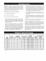
Owner's ManuaJ
®
POWER MISERTM
ELECTRIC
WATER HEATER
FOR POTABLE WATER HEATING ONLY.
NOT SUITABLE FOR SPACE HEATING.
9
MODEL NO.
153.329264 38 Gallon Short
153.329265 38 Gallon Short
153.329362 30 Gallon
i 52.329363 30 Gallon
i 53.329462 40 Gallon
i 53.329463 40 Gallon
i53.329562 55 Gallon
i 53.329563 55 Gallon
i 53.329662 65 Gallon
i 53.329663 66 Gallon
i 53.329862 80 Gallon
i 53.329863 80 Gallon
• Safety instructions
• installation
• Operation
• Care and Maintenance
• Troubleshooting
• Parts List
GAMA certification applies to all residential electric water heaters
with capacities of 20 to 120 Gallons. Input rating of 12kW or
less.
manual and safety messages
before installing, operating or
servicing this water heater.
Failure to follow instructions and
safety messages could result in
death or serious injury.
Instruction manual must remain
with water heater.
SAVE THiS MANUAL FOR FUTURE REFERENCE.
Sears, Roebuck and Co., Hoffman Estates, IL 60179 U.S.A
PRINTED0707 www.seats.com 185797-000

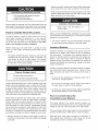
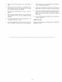
Your safety and the safety of others is extremely important in the installation, use and servicing of this water heater.
Many safety=related messages and instructions have been provided in this manual and on your own water heater to warn you
and others of a potential injury hazard. Read and obey all safety messages and instructions throughout this manual. It is very
important that the meaning of each safety message is understood by you and others who install, use or service this water
heater.
This is the safety alert symbol. It is used to alert you
to potential personal injury hazards. Obey all safety
messages that follow this symbol to avoid possible
injury or death.
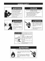
DANGER indicates an imminently
hazardous situation which, if not avoided,
could result in death or injury.
WARNING indicates a potentially
hazardous situation which, if not avoided,
could result in death or injury.
CAUTION indicates a potentially
hazardous situation which, if not avoided,
may result in minor or moderate injury.
CAUTION used without the safety alert
symbol indicates a potentially hazardoussituation which, if not avoided, could
result in property damage.
All safety messages wil! generally tell you about the type of hazard, what can happen if you do not follow the safety message
and how to avoid the risk of injury.
The California Safe Drinking Water and Toxic Enforcement Act requires the Governor of California to publish a list of substances
known to the State of California to cause cancer, birth defects, or other reproductive harm, and requires businesses to warn
of potential exposure to such substances.
This product contains a chemical known to the State of California to cause cancer, birth defects, or other reproductive harm.
This appliance can cause low level exposure to some of the substances listed, including formaldehyde.
IMPORTANT DEFINITIONS
Sears Service Center: The Sears Service Center has the ability equivalent to a licensed tradesman in the fields of plumbing and
electrical work including a thorough understanding of the requirements of the National Electrical Code as it relates to the
installation of electric water heaters. The Sears Service Center also has a thorough understanding of this instruction manual,
and is able to perform repairs strictly in accordance with the service guidelines provided by the manufacturer.

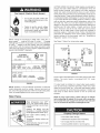
Readandunderstandinstruction
manualandsafetymessages
beforeinstalling,operatingor
servicingthiswaterheater.
Failuretofollowinstructionsand
safetymessagescouldresultin
deathorseriousinjury.
Instructionmanualmustremain
withwaterheater.
improper installation and use may result
in property damage.
- Do not operate water heater if flood damaged.
- Inspect and replace the anode as needed.
- Install in location with drainage.
- Fill tank with water before operation.
- Be alert for thermal expansion.
Refer to instruction manual for installation and service.
)
Explosion Hazard
• Overheated water can cause
water tank explosion.
• Properly sized temperature
and pressure relief valve must
be installed in opening
provided.
I
Before removing any access
panels or servicing the water
heater, make sure the electrical
supply to the water heater is
turned "OFF".
• Failure to do this could result in
death, serious bodily injury, or
property damage.
Water temperature over 125°F
(52°C) can cause severe burns
instantly resulting in severe injury
or death.
Children, the elderly, and the
physically or mentally disabled
are at highest risk for scald injury.
Feel water before bathing or
showering.
Temperature limiting valves are
available.
Read instruction manual for safe
temperature setting.
Fire Hazard / Electric Shock Hazard
Do not use this water heater with any
voltage other than shown on the model
rati ng plate.
• Failure to use the correct voltage shown
on the model rating plate could result in
death, serious bodily injury, or property
damage.

"q!
SAFE INSTALLATION, USEAND SERVICE ........................................................................................................................................ 2
GENERAL SAFETY ............................................................................................................................................................................. 3
TABLE OF CONTENTS ....................................................................................................................................................................... 4
INTRODUCTION ................................................................................................................................................................................ 5
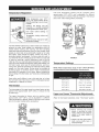
PRODUCT SPECIFICATIONS ............................................................................................................................................................ 5
MATERIALS AND BASIC TOOLS NEEDED ........................................................................................................................................ 6
Materials Needed ........................................................................................................................................................................ 6
Basic Tools .................................................................................................................................................................................. 6
Additional Tools Needed When Sweat Soldering ....................................................................................................................... 6
INSTALLATION INSTRUCTIONS ................................................................................................................................................... 7-16
Removing the Old Water Heater .............................................................................................................................................. 7,8
Facts to Consider About the Location ......................................................................................................................................... 8
Insulation Blankets ...................................................................................................................................................................... 8
Facts to Consider About the Convertible Lower Element ........................................................................................................ 8,9
Water Piping ........................................................................................................................................................................... 9,10
T & P Valve and Pipe Insulation ................................................................................................................................................. 10
Temperature-Pressure Relief Valve ..................................................................................................................................... 10,11
Filling the Water Heater ............................................................................................................................................................. 11
Converting the Lower Element ............................................................................................................................................. 11-14
Wiring .................................................................................................................................................................................... 14,15
Wiring Diagrams ....................................................................................................................................................................... 16
SERVICEANDADJUSTMENT .................................................................................................................................................... 17-22
Temperature Regulation ........................................................................................................................................................... 17
Thermostat ................................................................................................................................................................................ 17
Temperature Settings ................................................................................................................................................................ 17
Upper and Lower Thermostat Adjustments ......................................................................................................................... 17,18
Anode Rod Inspection ............................................................................................................................................................... 18
Temperature-Pressure Relief Valve Operation ......................................................................................................................... 18
Draining ................................................................................................................................................................................ 18,19
Thermostat Removal/Replacement .......................................................................................................................................... 19
Element Cleaning/Replacement ......................................................................................................................................... 19-22
Drain Valve Washer Replacement ..............................................................................................................................................
Service .........................................................................................................................................................................................
TROUBLESHOOTING GUIDE .................................................................................................................................................... 23-25
Start Up Conditions ................................................................................................................................................................... 23
Thermal Expansion ............................................................................................................................................................ 23
Strange Sounds ................................................................................................................................................................. 23
Operational Conditions ....................................................................................................................................................... 23-25
Smelly Water .................................................................................................................................................................. 23,24
"Air" in Hot Water Faucets .................................................................................................................................................. 24
Rumbling Noise .................................................................................................................................................................. 24
High Temperature Shut Off System .................................................................................................................................... 24
Not Enough or No Hot Water ......................................................................................................................................... 24,25
Water Is Too Hot .................................................................................................................................................................. 25
Leakage Checkpoints .......................................................................................................................................................... 25,26
REPAIR PARTS LIST .................................................................................................................................................................. 27-29
NOTES ......................................................................................................................................................................................... 30,31
WARRANTY ........................................................................................................................................................................................

ThankYouforpurchasingaSearswaterheater.Properly
installedandmaintained,itshouldgiveyouyearsoftrouble
freeservice.Itisstronglysuggestedthatthisnewwaterheater
beprofessionallyinstalled,contactthelocalSearsService
CenteroranySearsstore.Theywillarrangeforprompt,quality
installationbySearsauthorizedcontractors.
Abbreviations Found In This Instruction Manual:
UL - Underwriters Laboratories Inc.
NEC - National Electrical Code
ANSI -American National Standards Institute
Read the "General Safety" section, page 3 of this manual
first and then the entire manual carefully. If you don't follow
the safety rules, the water heater will not operate properly. It
could cause DEATH, SERIOUS BODILY INJURY AND/OR
PROPERTY DAMAGE.
This manual contains instructions for the installation,
operation, and maintenance of this electric water heater. It
also contains warnings throughout the manual that you must
read and be aware of. All warnings and all instructions are
essential to the proper operation of the water heater and
your safety. Since we cannot put everything on the first few
pages, READ THIS ENTIRE MANUAL BEFORE ATTEMPTING
TO INSTALL OR OPERATE THE WATER HEATER.
The installation must conform with the instructions in this
manual; electric company rules; and Local Codes, or in the
absence of Local Codes, with the current edition of the
NEC - National Electrical Code, NFPA 70. This publication
is available from your local government or public library or
electric company or by writing Underwriters Laboratories
Inc., 333 Pfingsten Road, Northbrook, IL 60062.
If after reading this manual you have any questions or do
not understand any portion of the instructions, call Sears
Service Center.
Carefully plan the place where you are going to put the water
heater. Correct electrical wiring and connections are very
important in preventing death from possible electrical shock
and fires.
Examine the location to ensure the water heater complies with
the "Facts to Consider About the Location" section.
For California installation this water heater must be braced,
anchored, or strapped to avoid falling or moving during an
earthquake. See instructions for correct installation procedures.
Instructions may be obtained from the California Office of the
State Architect, 400 P Street, Sacramento, CA 95814.
Massachusetts Code requires this water heater to be installed
in accordance with Massachusetts 248-CMR 2.00; State
Plumbing Code and 248-CMR 5.00. In the Commonwealth of
Massachusetts, this product must be installed by a licensed
plumber or gasfitter.
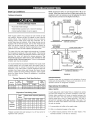
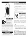
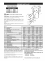
MODEL
NUMBER
153.329264
153.329265
153.329362
153.329363
153.329462
153.329463
153.329562
153.329563
153.329662
153.329663
153.329862
153.329863
TANK
CAPACITY
Gals Liters
38 I44
30 114
40 I51
55 208
66 250
80 303
DIMENSIONS
IN INCHES (ram)
DIA. HEIGHT
25.0 (635) 31.5 (800)
I9.0 (483) 47.0 (1,194)
I9.0 (483) 60.0 (1,524)
21.5 (546) 61.0 (1,549)
23.0 (584) 6I .0 (1,549)
25.0 (635) 61.5 (1,562)
ELEMENT
RECOVERY RATE WATTAGE
GALS,PER HOUR @240
VOLTS
,@_90°FRise UPPER LOWER
17.3 3800 3800
25.0 3800 5500
I7.3 3800 3800
25.0 3800 5500
17.3 3800 3800
25.0 3800 5500
17.3 3800 3800
25.0 3800 5500
17.3 3800 3800
25.0 3800 5500
17.3 3800 3800
25.0 3800 5500
MINIMUM
WIRE SIZE*
{GAUGE)
12
10
12
10
12
10
12
10
12
10
12
10
MAXIMUM FUSE
OR CiRCUiT
BREAKER
SIZE (AMPS)
2O
3O
2O
3O
2O
3O
2O
3O
2O
3O
2O
3O
Wiring size based on standard 60°C copper wire. If distance from fuse box to water heater is more than 90 feet, refer to your local electrical
code.

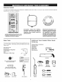
Materials Needed
To simplify the installation Sears has available the installation parts shown below. You may or may not need all of these materials,
depending on your type of installation.
m
WATER HEATER INSTALLATION KIT WITH
FLEXIBLE CONNECTORS FOR 3/4" OR 1/2"
THREADED OR COPPER PLUMBING
EXPANSION TANKS FOR THERMAL
EXPANSION CONDITIONS AVAILABLE IN 2
GALLONS , AND 5 GALLONS CAPACITY
THROUGH LOCAL SEARS STORE OR
SERVICE CENTER.
DRAIN PANS AVAILABLE IN 20"
DIAMETER FORWATER HEATERS
HAVING A DIAMETER 18" OR LESS,
24" DIAMETER FOR WATER
HEATERS HAVING A DIAMETER 22"
OR LESS AND AVAILABLE IN 28"
DIAMETER FOR WATER HEATERS
HAVING A DIAMETER 26" OR LESS.
Basic Tools
You may or may not need all of these tools, depending on your
type of installation. These tools can be purchased at your local
Sears store.
Pipe Wrench (2)
Screwdriver
6 Foot Tape or Folding Rule
Garden Hose
Drill
Pipe Dope or Teflon Tape
DRILL
ROLL OF TEFLON TAPE (USE ON
WATER CONNECTIONS)
SLOT-HEAD SCREWDRIVER
PHILLIPS SCREWDRIVER
PiPE DOPE (SQUEEZE TUBE)
USE FOR WATER CONNECTIONS
GARDEN HOSE 6 FOOT TAPE PiPE WRENCH
Additional Tools Needed When Sweat
Soldering
Tubing Cutters or Hacksaw
Propane Torch
Soft Solder
Solder Flux
Emery Cloth
Wire Brushes
TUBING CUTTER
HACKSAW
ROLL OF ROLL OF
EMERY CLOTH LEAD-FREE SOLDER
SOFT SOLDER FLUX
PROPANE
TORCH
3/4" (19 mm) WIRE BRUSH
1/2" (13 ram) WIRE BRUSH

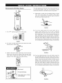
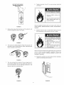
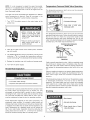
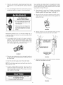
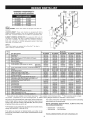
Removing the Old Water Heater
1. Turn "OFF" electrical supply to the water heater.
FIGURE 1.
2. Turn "OFF" the water supply to the water heater at the water
shut-off valve or water meter.
FIGURE 2.
3. Attach a hose to the water heater drain valve and put the
other end in a floor drain or outdoors. Open the water drain
valve. Open a nearby hot water faucet which will relieve
pressure in the water heater and speed draining.
FIGURE 3.
The water passing out of the drain valve may be extremely hot.
To avoid being scalded, make sure all connections are tight
and that the water flow is directed away from any person.
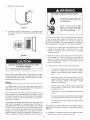
4.
Check again to make sure the electrical supply is turned
"OFF" to the water heater. Then unplug the water heater
(cord set) or disconnect the electrical supply connection
from the water heater junction box.
FIGURE 4.
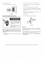
5a.
If you have copper piping to the water heater, the two
copper water pipes can be cut with a hacksaw
approximately four inches away from where they connect
to the water heater. This will avoid cutting off the pipes too
short. Additional cuts can be made later if necessary.
Disconnect the temperature-pressure relief valve drain line.
When the water heater is drained, disconnect the hose
from the drain valve. Close the drain valve. The water heater
is now completely disconnected and ready to be removed.
FIGURE 5a,
5b. If you have galvanized pipe to the water heater, loosen the
two galvanized pipes with a pipe wrench at the union in
each line. Also disconnect the piping remaining to the water
heater. These pieces should be saved since they may be
needed when reconnecting the new water heater.
Disconnect the temperature-pressure relief valve drain line.
When the water heater is drained, disconnect the hose
from the drain valve. Close the drain valve. The water heater
is now completely disconnected and ready to be removed.
, Burn hazard
• Hotwater discharge.
• Keep hands clear of drain
valve discharge.

MineralBuildup or Sediment IVlayAccumalate
. This causes the water heater to become
much heavier than normal.
® Ifspilled, could cause staining.
Mineral buildup or sediment may have accumulated in the old
water heater. This causes the water heater to be much heavier
than normal and this residue, if spilled out, could cause staining.
Facts to Consider About the Location
You should carefully choose an indoor location for the new
water heater, because the placement is a very important
consideration for the safety of the occupants in the building
and for the most economical use of the appliance. This water
heater is not intended for outdoor installation.
Whether replacing an old water heater or putting the water
heater in a new location, the following critical points must be
observed.
The location selected should be indoors as close to and as
centralized with the water piping system as possible. This
water heater, as well as all water heaters, will eventually
leak. Do not install without adequate drainage provisions
so water flow will not cause damage.
Property Damage Hazard
* All water heaters eventually leak
Do not install without adequate drainage.
• Sensors mounted in the drain pan that turn offthe water supply
to the entire home when water is detected in the drain pan.
• Water supply shut-off devices that activate based on the water
pressure differential between the cold water and hot water
pipes connected to the water heater.
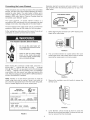
Installations in Residential Garages
. Water heater must be located in a
protective area.
INSTALLATION IN RESIDENTIAL GARAGES: The water heater
must be located and/or protected so it is not subject to physical
damage by a moving vehicle.
The location selection must provide adequate clearances
for servicing and proper operation of the water heater.
Insulation Blankets
Insulation blankets are available to the general public for
external use on electric water heaters but are not necessary
with this product. The purpose of an insulation blanket is to
reduce the standby heat loss encountered with storage tank
heaters. Your water heater meets or exceeds the National
Appliance Energy Conversation Act standards with respect to
insulation and standby loss requirements, making an insulation
blanket unnecessary.
Should you choose to apply an insulation blanket to this heater,
you should follow these instructions below. Failure to follow
these instructions can result in fire, serious personal injury, or
death.
Do not cover the temperature and pressure relief (T & P)
valve with an insulation blanket.
WATER HEATERS EVENTUALLY LEAK: Installation of the water
heater must be accomplished in such a manner that if the tank
or any connections should leak, the flow of water will not cause
damage to the structure. When such locations cannot be
avoided, a suitable drain pan should be installed under the
water heater. Drain pans are available at your local Sears stores.
Such drain pans must be piped to an adequate drain.
Water heater life depends upon water quality, water pressure
and the environment in which the water heater is installed.
Water heaters are sometimes installed in locations where
leakage may result in property damage, even with the use of a
drain pan piped to a drain. However, unanticipated damage
can be reduced or prevented by a leak detector or water shut-
off device used in conjunction with a piped drain pan. These
devices are available from some plumbing supply wholesalers
and retailers, and detect and react to leakage in various ways:
• Sensors mounted in the drain pan that trigger an alarm or
turn off the incoming water to the water heater when leakage
is detected.
Do not cover the instruction manual. Keep it on the side of
the water heater or nearby for future reference.
Do obtain new warning and instruction labels for placement
on the blanket directly over the existing labels.
Facts to Consider About the
Convertible Lower Element
The Upper Element (if a double element model) is a
conventional 3800 watt element which only operates at its rated
wattage on 240 volts. (See rating plate on the water heater).
The Lower Element of the water heater can be converted from
operation at 3800 watts to 5500 watts on a 240 volt system.
Read and follow water heater warnings and instructions. If
after reading these instructions in this manual, you do not
understand any portion, call Sears Service Center.

Fire Hazard / Electric Shock Hazard
- Do not use this water heater with
any voltage other than shown on the
model rating plate.
- Failure to use the correct voltage
shown on the model rating plate
could result in death, serious bodily
injury, or property damage.
Before making the conversion to 5500 watts, check the (1)
power supply . . . must be 240 volts, (2) wiring . . . 10 gauge
AWG @ Type TW, 60°C or equivalent, and (3) Circuit breakers
or fusing . . .capable of 30 amp loading. Also, the installation
must conform with this manual, local codes and electric utility
rules. Failure to comply can result in DEATH, SERIOUS BODILY
INJURY, OR PROPERTY DAMAGE.
ELECTRIC Q LISTED
WATE R H EATER 932N
CAPACITY
MODEL NUMBER U.S. GAL. SERIAL NUMBER
FACTORY EQUIPPED WITH
MAXIMUM
UPPER LOWER CHECK HERE WORKING
ELEMENT ELEMENT MAXIMUM VOLTS IF INSTALLED AS PRESSURE
WATTS WATTS WATTS A,C, ONLY FACTORY EQUIPPED P.S.I.
OPTIONAL WATTAGE
UPPER LOWER
ELEMENT ELEMENT MAXIMUM CHECK HERE
WATTS WATTS WATTS IF CONVERTED
WARNING
SEE CONVERSION
INSTRUCTION
FIGURE 6.
NOTE: Whether or not the element conversion is made the
model rating plate must be marked. Using a hard point ink
pen, check the appropriate block within the model rating plate,
which is located adjacent to the lower access panel.
Water Piping
Water temperature over 125°F
(52°C) can cause severe burns
instantly resulting in severe injury
or death.
Children, the elderly, and the
physically or mentally disabled
are at highest riskfor scald injury.
Feel water before bathing or
showering.
Temperature limiting valves are
available.
Read instruction manual for safe
temperature setting.
HOTTER WATER CAN SCALD: Water heaters are intended to
produce hot water. Water heated to a temperature which will
satisfy clothes washing, dish washing, and other sanitizing
needs can scald and permanently injure you upon contact.
Some people are more likely to be permanently injured by hot
water than others. These include the elderly, children, the infirm,
or physically/mentally handicapped. If anyone using hot water
in your home fits into one of these groups or if there is a local
code or state law requiring a certain temperature water at the
hot water tap, then you must take special precautions. In
addition to using the lowest possible temperature setting that
satisfies your hot water needs, a means such as a mixing
valve, should be used at the hot water taps used by these
people or at the water heater. Mixing valves are available at
plumbing supply or hardware stores. Follow manufacturers
instructions for installation of the valves. Before changing the
factory setting on the thermostat, read the "Temperature
Regulation" section in this manual.
See Figure 7 (below) for mixing valve usage.
HOT WATER
OUTLET
COLD
WATER
iNLET
WATER
OUTLET
*MIXING
VALVE
f
FROMHOTWATER
OUTLETON
WATER HEATER
TO COLD WATER
iNLET ONWATER HEATER
FIGURE 7.
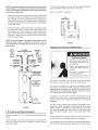
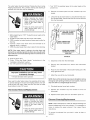
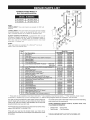
Figure 8 shows the attachment of the water piping to the water
heater. The water heater is equipped with 3/4" water
connections.
If a water heater is installed in a closed water supply system;
such as one having a back-flow preventer, check valve, water
meter with a check valve, etc.., in the cold water supply; means
must be provided to control thermal expansion. Contact the
local utility or Sears Service Center on how to control this
situation.
NOTE: If using copper tubing, solder tubing to an adapter
before attaching the adapter to the water inlet connection.
Do not solder the water supply lines directly to the cold water
inlet. It will harm the dip tube and damage the tank.
Property Damage Hazard
• Avoid water heater damage.
- Install thermal expansion tank if necessary.
• Do not apply heat to cold water inlet.
• Contact qualified installer or service agency.

NOTE:Toprotectagainstuntimelycorrosionofhot and cold
water fittings, it is strongly recommended that di=electric
unions or couplings be installed on this water heater when
connected to copper pipe.
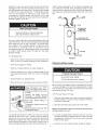
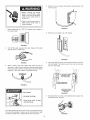
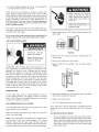
Fit T & P valve insulation over valve. Make sure that the insulation
does not interfere with the lever of the T & P valve.
Secure all insulation using tape.
1. Look at the top cover of the water heater. The hot water outlet
is marked hot. Put two or three turns of teflon tape around
the threaded end of the threaded-to-sweat coupling and
around both ends of the 3/4" threaded nipple. Using flexible
connectors, connect the hot water pipe to the hot water outlet
of the water heater.
2. Look at the top cover of the water heater. The cold water inlet
is marked cold. Put two or three turns of teflon tape around
the threaded end of the threaded-to-sweat coupling and
around both ends of the 3/4" threaded nipple. Using flexible
connectors, connect the cold water pipe to the cold water
inlet of the water heater.
NOTE: Your water heater is insulated to minimize heat loss
from the tank, Further reduction in heat loss can be
accomplished by insulating the hot water lines from the
water heater,
HOT FLEXIBLE SHUT-OFF
OUTLET WATER CONNECTORS VALVE
TO
HOUSE [_
l COLD
INLET
THREADED THREADED WATER
TO SWEAT TO SWEAT LINE
COUPLING COUPLING
3/4" THREADED - 3!4" THREADED
NIPPLE '=""___--_'- NIPPLE
HOT _ COL
TEMPERATURE-
PRESSURE
RELIEF VALVE
DISCHARGE
-- PIPE
(DO NOT CAP
OR PLUG)
6"
FLOOR DRAIN
FIGURE 8.
T & P Valve and Pipe Insulation
Remove insulation for T & P valve and pipe connections from
carton.
Fit pipe insulation over the incoming cold water line and the hot
water line. Make sure that the insulation is against the top
cover of the heater.
PIPE
INSULATION
:'= T&P ('_
iNSULATION "_\_/_
FIGURE 9.
Temperature-Pressure Relief Valve
/
Explosion Hazard
•Tem perature-pressure relief valve
must comply with ANSI A21.22
andASMEcode.
" Properly sized temperature-relief
valve must be installed in opening
provided.
• Can result in overheating and
excessive tank pressure.
, Can cause serious injury or death.
This heater is provided with a properly certified combination
temperature - pressure relief valve by the manufacturer.
The valve is certified by a nationally recognized testing
laboratory that maintains periodic inspection of production of
listed equipment of materials as meeting the requirements for
Relief Valves for Hot Water Supply Systems, ANSI Z21.22 • CSA
4.4, and the code requirements of ASME.
If replaced, the valve must meet the requirements of local
codes, but not less than a combination temperature and
pressure relief valve certified as indicated in the above
paragraph.
The valve must be marked with a maximum set pressure not to
exceed the marked hydrostatic working pressure of the water
heater (150 psi = 1,035 kPa) and a discharge capacity not less
than the water heater input rate as shown on the model rating
plate. (For electric heaters, watts x 3.412 equals Btu/hr input
rate)
For safe operation of the water heater, the relief valve must not
be removed from its designated opening nor plugged.
The temperature-pressure relief valve must be installed directly
into the fitting of the water heater designed for the relief valve.
10

Positionthevalvedownwardandprovidetubingsothatany
dischargewillexitonlywithin6inches(153mm)above,orat
anydistancebelowthestructuralfloor.Becertainthatnocontact
ismadewithanyliveelectricalpart.Thedischargeopening
mustnot be blockedor reducedin size underany
circumstances.Excessivelength,over30feet(9.14m),oruse
ofmorethanfourelbowscancauserestrictionandreducethe
dischargecapacityofthevalve.
Ifaftermanuallyoperatingthevalve,itfailstocompletelyreset
andcontinuestoreleasewater,immediatelyclosethecold
waterinlettothewaterheater,followthedraininginstructions,
andreplacethetemperature-pressurereliefvalvewithanew
one.
HOT COLD
Water Damage Hazard
• Temperature-pressure relief valve discharge
pipe must terminate at adequate drain.
No valve or other obstruction is to be placed between the relief
valve and the tank. Do not connect tubing directly to discharge
drain unless a 6 inch air gap is provided. To prevent bodily
injury, hazard to life, or property damage, the relief valve must
be allowed to discharge water in quantities should
circumstances demand. If the discharge pipe is not connected
to a drain or other suitable means, the water flow may cause
property damage.
The Discharge Pipe:
• Shall not be smaller in size than the outlet pipe size of the
valve, or have any reducing couplings or other restrictions.
• Shall not be plugged or blocked.
• Shall be of material listed for hot water distribution.
• Shall be installed so as to allow complete drainage of both
the temperature-pressure relief valve, and the discharge
pipe.
• Shall terminate at an adequate drain.
• Shall not have any valve between the relief valve and tank.
Water temperature over 125°F
(52°C) can cause severe burns
instantly resultingin severeinju_
ordeath.
Children, the elderly, and the
physically or mentally disabled
are at highest riskfor scald injury.
Feel water before bathing or
showering.
Temperature limiting valves are
available.
Read instruction manual for safe
temperature setting.
TEMPERATURE-
_RPRESSURE
ELIEF VALVE
-- DISCHARGE PiPE
(DO NOT CAP OR PLUG)
_6" AIR GAP
FLOOR DRAIN
FIGURE 10.
Filling the Water Heater
Property Damage Hazard
. Avoid water heater damage.
• Fill tank with water before operating.
Never use this water heater unless it is completely full of water.
To prevent damage to the tank and heating element, the tank
must be filled with water. Water must flow from the hot water
faucet before turning "ON" power.
To fill the water heater with water:
1. Close the water heater drain valve by turning the handle to
the right (clockwise). The drain valve is located on the lower
front of the water heater.
2. Open the cold water supply valve to the water heater.
NOTE: The cold water supply valve must be left open when
the water heater is in use.
The temperature-pressure relief valve must be manually
operated at least once a year. Caution should be taken to
ensure that (1) no one is in front of or around the outlet of the
temperature-pressure relief valve discharge line, and (2) the
water manually discharged will not cause any bodily injury or
property damage because the water may be extremely hot.
3. To insure complete filling of the tank, allow air to exit by
opening the nearest hot water faucet. Allow water to run until
a constant flow is obtained. This will let air out of the water
heater and the piping.
4. Check all new water piping for leaks. Repair as needed.
11

Converting the Lower Element
These instructions only cover the conversion of the convertible
element, read this entire manual before attempting to install or
operate the water heater. The water heater is factory set to
operate at 3800 watts. The lower element can be converted to
operate at 5500 watts. Refer to "Facts to Consider About the
Convertible Lower Element" section.
The Upper Element, (if double element model) is a
conventional 3800 watt element which only operates at its rated
wattage on 240 volts. (See rating plate on the water heater.)
The lower Element of the water heater can be converted from
operation at 3800 watts to 5500 watts on a 240 volt system.
If after reading these instructions and this manual, if you do not
understand any portion call Sears Service Center.
Fire Hazard / Electric Shock Hazard
Do not use this water heater with
any voltage other than shown on the
model rating plate•
Failure to use the correct voltage
shown on the model rating plate
could result in death, serious bodily
injury, or property damage.
Before making the conversion to 5500 watts, check the (1)
power supply . . . must be 240 volts, (2) wiring . . . 10 gauge
AWG @ Type TW, 60°C or equivalent, and (3) Circuit breakers
or fusing . . .capable of 30 amp loading. Also, the installation
must conform with this manual, local codes and electric utility
rules. Failure to comply can result in DEATH, SERIOUS BODILY
INJURY, OR PROPERTY DAMAGE.
NOTE: Whether or not the element conversion is made the
model rating plate must be marked. Using a hard point ink
pen, check the appropriate block within the model rating plate,
which is located adjacent to the lower access panel.
ELECTRIC Q LISTED
WATER HEATER 932N
CAPACITY
MODEL NUMBER U.S GAL SERIAL NUMBER
FACTORY EQUIPPED WiTH
MAXIMUM
UPPER LOWER CHECK HERE WORKING
ELEMENT ELEMENT MAXIMUM VOLTS }FINSTALLEDAS PRESSURE
WATTS WATTS WATTS A.C. ONLY FACTORY EQUIPPED P,S I
OPTIONAL WATTAGE
UPPER LOWER
ELEMENT ELEMENT MAXIMUM CHECKHERE
WATTS WATTS WATTS IFCONVERTED
WARNING
SEE CONVERSION
INSTRUCTION
FIGURE 11.
Necessary element conversion parts are located in a small
bag contained within the electrical junction box on top of the
water heater.
CONVERSION PARTS
BUSS BAR
FIGURE 12.
Before beginning the conversion turn "OFF" electric power
supply to the water heater.
FIGURE 13.
The convertible element is located behind the lower
access panel of the water heater. Remove the two screws
securing the access panel, and remove panel.
FIGURE 14.
3. Remove the insulation cap with handle to expose the
terminal cover.
12
FIGURE 15.
Lower Element: Lift out the tab as shown to unclip the
terminal cover from the thermostat. The terminal cover can
now be removed from the thermostat.

5.
6.
LiFT OUT TAB TO UNCLIP
TERMINAL COVER FROM
THERMOSTAT
FIGURE 16.
Remove the screws from terminal 2 of the element, and
move the looped end of the wire aside.
FIGURE 17.
The buss bar is labeled 5500 W. Place the buss bar over
terminals 2 and 3 with the 5500 W visible. Install the extra
screw provided into terminal 3.
8. Tighten terminals 2 and 3 to ensure proper electrical
connection.
Fire and Explosion Hazard
• Failure to tighten screws can
cause a fire.
• Failure to do this could result in
death, serious bodily injury, or
property damage.
Failure to tighten terminal screws can cause a fire which can
result in DEATH, SERIOUS BODILY INJURY, OR PROPERTY
DAMAGE.
9. Replace terminal cover on thermostat making sure that
the locking tabs on the terminal cover are in place.
Fire and E×plosion Hazard
= Thermostat must be flush
againstthe tank.
,, Make sure terminal cover is in
place and the insulation
replaced.
e Failure to do this could result in
death, serious bodily injury, or
property damage.
7.
5500W
FIGURE 18.
The wire removed from terminal 2 has a looped end. It
must remain looped and now be placed (as shown) on
top of the buss bar, over the opening of terminal 2, and
secured using the remaining screw.
Make sure the thermostat is flush against the tank, the terminal
cover is in place, and the insulation is replaced. Failure to do
so can result in DEATH, SERIOUS BODILY INJURY, OR
PROPERTY DAMAGE.
10. Replace the insulation cap with handle so that it completely
covers the thermostat and element.
Q
FIGURE 19.
13
FIGURE 20.

11. Replace the access panel.
FIGURE 21.
12. Complete wiring to the water heater, or if completed, turn
"ON" electric power to the water heater after filling the tank
with water.
FIGURE 22,
improper installation and use may result
in property damage.
. Fill tank with water before operation.
Never use this water heater unless it is completely full of water.
To prevent damage to the tank and heating element, the tank
must be filled with water. Water must flow from the hot water
faucet before turning "ON" power.
Wiring
You must provide all wiring of the proper size outside of the
water heater. You must obey local codes and electric company
requirements when you install this wiring.
If you are not familiar with electric codes and practices, or if you
have any doubt, even the slightest doubt, in your ability to connect
the wiring to this water heater, obtain the service of a competent
electrician. Contact your Sears salesperson to arrange for a
professional electrician.
WATER HEATERS EQUIPPED FOR ONE VOLTAGE ONLY: This
water heater is equipped for one type voltage only. Check the
rating plate near the bottom access panel for the correct voltage.
DO NOT use this water heater with any voltage other than the
one shown on the model rating plate. Failure to use the correct
voltage can cause problems which can result in DEATH,
SERIOUS BODILY INJURY, OR PROPERTY DAMAGE. If you
have any questions or doubts consult your electric company.
Fire Hazard / Electric Shock Hazard
®
Do not use this water heater with
any voltage other than shown on the
model rating plate.
Failure to use the correct voltage
shown on the model rating plate
could result in death, serious bodily
injury, or property damage.
14
If wiring from your fuse box or circuit breaker box was aluminum
for your old water heater, replace it with copper wire. If you wish
to reuse the existing aluminum wire, have the connection at
the water heater made by a competent electrician. Contact your
Sears salesperson to arrange for a professional electrician.
Provide a way to easily shut off the electric power when
working on the water heater. This could be with a circuit
breaker or fuse block in the entrance box or a separate
disconnect switch.
Install and connect a circuit directly from the main fuse or
circuit breaker box. This circuit must be the right size and
have its own fuse or circuit breaker. Refer to the chart in the
"Product Specifications" section for the correct size wire and
fuse or circuit breaker.
3. If metal conduit is used for the grounding conductor:
The grounding electrode conductor shall be of copper,
aluminum, or copperclad aluminum. The material
shall be of one continuous length without a splice or
joint.
Rigid metal conduit, intermediate metal conduit, or
electrical metallic tubing may be used for the grounding
means if conduit or tubing is terminated in fittings
approved for grounding.
Flexible metal conduit or flexible metallic tubing shall
be permitted for grounding if all the following
conditions are met:
The length in any ground return path does not exceed
6 feet.
The circuit conductors contained therein are protected
by overcurrent devices rated at 20 amperes or less.
The conduit or tubing is terminated in fittings approved
for grounding.
For complete grounding details and all allowable exceptions,
refer to the current edition of the NEC - National Electrical Code
NFPA70.
4. A standard 1/2" conduit opening has been made in the water
heater junction box for the conduit connection.

5.WiringDiagrams(see"Wiring Diagrams" section) have been
supplied showing the two most common types of
connections between the water heater and the power supply.
You can easily see which type connection you have by
removing the junction box cover on top of the water heater.
Two Wire Connection Diagrams: is the most common
requiring you to simply connect red to red, black to
black, and the ground wire to the green ground screw
in the junction box of the water heater.
Three Wire Connection Diagram: is used when you
are connecting the water heater to a power supply
that has a "Time Clock" or "Off Peak" meter. To make
these connections refer to block 1 or 2 in this wiring
diagram for the type of system you have.
NOTE: If you have purchased a three wire connection water
heater but you are not on a "Time Clock" or "Off Peak" meter
and have a standard two wire connection power supply,
simply follow the connection diagram in block 3 of the three
wire connection diagram.
6. Use wire nuts and connect the power supply wiring to the
wires inside the water heater's junction box.
7. The water heater must be electrically "grounded" by the
installer. A green ground screw has been provided on the
water heater's junction box. Connect ground wire to this
location.
8. Replace the wiring junction cover using the screw provided.
CONDUIT
WiRE NUT
GREEN
.GROUND
FIGURE 23.
15

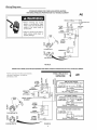
Wiring Diagrams
[
STANDARD WIRING FOR 2 WIRE LEAD WATER HEATERS
NON-SIMULTANEOUS OPERATION 240 VOLT DOUBLE ELEMENT
A6
GROUNDTE"M'NAL------F:-_I_--
* Before removing any access ,, Tl__T2?owersuPpLY
panels or servicing the water ol ,.,I
heater, make sure the electrical HI-TEMP JUNCTION
supply to the water heater is LImit-_l(_'ll_-@l / BOX
turned "OFF". SWITCH rJK_ I_
oP.E. _q
, Failure to do this could result in THERMOSTAT .___ /
death, serious bodily injury, or _ Lu
property damage. BUSS OI _ _1
_ I f ELEMENT O
<l ./_.. I_ _ -,
FOR5500WATTS I('_ I
THERMOSTAT"-*I - \ I
_ bu o
LOWERHEATI
FOR3800WATTS__
FIGURE 24.
WIRING FOR 3 WIRE LEAD WATER HEATERS NON=SIMULTANEOUS OPERATION 240VOLT DOUBLE ELEMENT
*NOTE: Some lower Hi-Temp Limit Switches
may have 4 terminals. Use only the
2 terminals on left.
UPPER J3_J _uJ_j _:,_
HI-TEMP_ _,
SWITCH ,.m_I I__ I I
UPPER {'_
T.ERMOSTAT__ i l I
,nO,CATOR
(OPTIONAL) :-C-_-)I' _1 -_1al I
BUSS X UPPER HEATING-- --_£;/-------J I I
" \ of 5_ n,-TEMP
LOWER---._1-% I
OR°°00WATTS,HERMO% I
I
OI A la LOWER _l
FOR 38°0 WATTS FIGURE 25.
A9
,,=,
o_
#_
0
1. TIME CLOCK SWITCH
OPERATES BOTTOM ELEMENT ONLY
TOELECTRIC _L2 _ tOTIme
POWER SUPPLY _ CLOCK SWITCH
_ JUNCTION BOX
YELLOW I !:BLUEI BLACK
2. "OFF PEAK" METER
OPERATES BOTTOM ELEMENT ONLY
TO ELECTRIC .,--_==-L2 LI_ TO "OFF PEAK"
POWER SUPPLY_ METER
_ JUNCTION BOX
YELLOW _ T BLUEi BLACK
3. FOR TWO WIRE CONNECTION
TO ELECTRIC
POWER SUPPLY LI L2
_ JUNCTION BOX
YELLOWI _FBLLIE_BLACK
16

Temperature Regulation
Water temperature over 125°F
(52°C) can cause severe burns
instantly resulting in severe injury
or death•
Children, the elderly, and the
physically or mentally disabled
are at highest risk for scald injury.
Feel water before bathing or
showering•
Temperature limiting valves are
available.
Read instruction manual for safe
temperature setting.
HOTTER WATER CAN SCALD: Water heaters are intended to
produce hot water• Water heated to a temperature which will
satisfy clothes washing, dish washing, and other sanitizing
needs can scald and permanently injure you upon contact• Some
people are more likely to be permanently injured by hot water
than others• These include the elderly, children, the infirm, or
physically/mentally handicapped• If anyone using hot water in
your home fits into one of these groups or if there is a local code
or state law requiring a certain temperature water at the hot
water tap, then you must take special precautions• In addition to
using the lowest possible temperature setting that satisfies your
hot water needs, some type of tempering device, such as a
mixing valve, should be used at the hot water taps used by these
people or at the water heater• Mixing valves are available at
plumbing supply or hardware stores• Follow manufacturers
instructions for installation of the valves, Before changing the
factory setting of the thermostat, see Temperature Settings table
at right•
Never allow small children to use a hot water tap, or to draw
their own bath water• Never leave a child or handicapped person
unattended in a bathtub or shower•
Thermostat
The thermostats of this water heater have been factory set at a
position which approximates 120°F (49°C), to reduce the risk
of scald injury•
The upper thermostat is factory set at a position which
approximates 120°F (49°C), and is adjustable if a different
water temperature is desired• Read all warnings in this manual
and on the water heating before proceeding•
m_
,w
_j IL
ADJUSTABLE UPPER
THERMOSTAT BEHIND
UPPER ACCESS PANEL
PANEL {DUAL ELEMENT
r,AODELS ONLY)
TEMPERATURE
\ ADJUSTMENT
KNOB
ADJUSTABLE UPPER THERMOSTAT
FIGURE 26.
The lower thermostat is factory set at a position which
approximates 120°F (49°C), and is adjustable if a different
water temperature is desired• Read all warnings in this manual
and on the water heating before proceeding•
TEMPERATURE
ADJUSTMENT
KNOB
ADJUSTABLE
LOWER
THERMOSTAT(FOR
DUAL ELEMENT
MODELS)
m
ADJUSTABLE
LOWER
THERMOSTAT WITH
HIGH LIMIT
FIGURE 27.
Temperature Settings
NOTE: Water temperature range of 120°--140°F (49°-60°0)
recommended by most dishwasher manufacturers,
I60°F (71°C)
I50°F (66°C)
I40°F (60°C)
I30°F (54°C)
I20°F (49°C)
About 1/2 second
About 1-1/2 seconds
Less than 5 seconds
About 30 seconds
More than 5 minutes
Upper and Lower Thermostat Adjustments
(Refer to thermostat illustrations under "Thermostat" section)
I
Before removing any access
panels or servicing the water
heater, make sure the electrical
supply to the water heater is
turned "OFF".
• Failure to do this could result in
death, serious bodily injury, or
property damage.
17

NOTE:Itisnotnecessarytoadjusttheupperthermostat.
However,ifitisadjustedabovethefactorysetpointof120°F
(49°C),itisrecommendedthatitnotbesethigherthanthe
lowerthermostatsetting.
Theupperandlowerthermostatsareadjustableifadifferent
watertemperatureis desired.Readallwarningsin the
"Temperature-Regulation" section before proceeding.
1. Turn "OFF" the electric power to the water heater at the
junction box.
[
,, Before removing any access
panels or servicing the water
heater, make sure the electrical
supply to the water heater is
turned "OFF".
,, Failure to do this could result in
death, serious bodily injury, or
property damage.
2. Take off the upper and/or lower access panel, insulation
cap with handle.
3. The slotted adjustment (using a screwdriver) can be turned
clockwise ( f'_ ) to increase the temperature setting or
counter clockwise ( _'_ ) to decrease the temperature setting.
4. Replace the insulation cap with handle and access panel.
5. Turn "ON" the power supply.
Anode Rod Inspection
Property Damage Hazard
• Avoid water heater damage.
. Inspection and replacement of anode as needed.
The anode rod is used to protect the tank from corrosion. Most
hot water tanks are equipped with an anode rod. The
submerged rod sacrifices itself to protect the tank. Instead of
corroding the tank, water ions attack and eat away the anode
rod. This does not affect the water's taste or color. The rod
must be maintained to keep the tank in operating condition.
Anode deterioration depends on the water conductivity, not
necessarily water condition. A corroded or pitted anode rod
indicates high water conductivity and should be checked and/
or replaced more often than an anode rod that appears to be
intact. Replacement of a depleted anode rod can extend the
life of your water heater. Inspection should be conducted by
calling Sears Service Center. At a minimum the anode(s)
should be checked annually after the warranty period.
Temperature-Pressure Relief Valve Operation
The temperature-pressure relief valve must be manually
operated at least once a year.
• Burn hazard
• Hotwater discharge.
• Keep clear of relief valve
discharge outlet.
The temperature-pressure relief valve must be manually
operated at least once a year. Caution should be taken to ensure
that (1) no one is in front of or around the outlet of the
temperature-pressure relief valve discharge line, and (2) the
water manually discharged will not cause any property damage
or bodily injury. The water may be extremely hot.
TEMPERATURE_PRESSURE
DISCHARGE PiPE
FIGURE 28.
If after manually operating the valve, it fails to completely reset
and continues to release water, immediately close the cold
water inlet to the water heater, follow the draining instructions,
and replace the temperature-pressure relief valve with a new
one.
Failure to install and maintain a new properly listed temperature-
pressure relief valve will release the manufacturer from any
claim which might result from excessive temperature or
pressure.
If the temperature-pressure relief valve on the appliance weeps
or discharges periodically, this may be due to thermal
expansion. Your water heater may have a check valve installed
in the water line or a water meter with a check valve. Consult
your local Sears Service Center for further information. Do not
plug the temperature-pressure relief valve.
Draining
. Burn hazard
• Hot water discharge.
• Keep hands clear of drain
valve discharge.
18

Thewaterheatershouldbedrainedifbeingshutdownduring
freezingtemperatures.Also,periodicdrainingandcleaningof
sedimentfromthetankmaybenecessary.
l
• Before removing any access
panels or servicing the water
heater, make sure the electrical
supply to the water heater is
turned "OFF".
Failure to do this could result in
death, serious bodily injury, or
property damage.
1. Before beginning turn "OFF" the electric power supply to the
water heater.
2. CLOSE the cold water inlet valve to the water heater.
3. OPEN a nearby hot water faucet and leave open to allow for
draining.
4. Connect a hose to the drain valve and terminate to an
adequate drain or outdoors.
5. OPEN the water heater drain valve to allow for tank draining.
NOTE: If the water heater is going to be shut down and
drained for an extended period, the drain valve should be left
open with hose connected allowing water to terminate to an
adequate drain.
6. Close the drain valve.
7. Follow "Filling the Water Heater" instructions in the
"Installation Instructions" section.
8. Turn "ON" power to the water heater.
1. Turn "OFF" the electrical power to the water heater at the
junction box.
2. Remove the access panel and the insulation cap with
handle.
3. Lift out the tab as shown below to unclip the terminal cover
from the thermostat. The terminal cover can now be removed
from the thermostat.
LIFT OUT TAB TO UNCLIP
TERMINAL COVER
FROM THERMOSTAT
LOWER THERMOSTAT
WITHOUT HIGH LIMIT
UPPER AND LOWER
THERMOSTAT WITH
HIGH LIMIT
FIGURE 29.
4. Disconnect wires from the thermostat.
5. Remove the thermostat from behind the thermostat
bracket.
improper installation and use may result
in property damage.
• Fill tank with water before operation.
Never use this water heater unless it is completely full of water.
To prevent damage to the tank and heating element, the tank
must be filled with water. Water must flow from the hot water
faucet before turning "ON" power.
6. Place the new thermostat in the bracket making sure it fits
firmly against the tank.
7. Attach the wires to the new thermostat.
NOTE: Some of the terminals may require straight-in wiring
through an eye-opening. If wires are now looped, recur and
strip wire 3/8" to a straight length and insert.
8. Put plastic terminal cover back in place.
Thermostat Removal/Replacement
9. Replace the insulation cap with handle to cover the
thermostat.
l
-Before removing any access
panels or servicing the water
heater, make sure the electrical
supply to the water heater is
turned "OFF".
• Failure to do this could result in
death, serious bodily injury, or
property damage.
10. Replace access panel, then turn the electric power on.
19
Element Cleaning/Replacement
NOTE: These instructions are written for element cleaning and
element replacement for the lower element. If it is necessary to
clean or replace the upper element, then repeat these
instructions.
To remove the element from your tank in order to clean or
replace it.

[
o Before removing any access
panels or servicing the water
heater, make sure the electrical
supply to the water heater is
turned "OFF".
• Failure to do this could result in
death, serious bodily injury, or
property damage.
Remove the two screws securing the access panel, and
remove panel.
Before beginning turn "OFF" the electric power supply to
the water heater.
FIGURE 33.
5. Remove the insulation cap with handle.
2.
3.
FIGURE 30.
Turn off the water supply to the water heater at the water
Shut-off valve or water meter.
FIGURE 31.
Attach a hose to the water heater drain valve and put the
other end in a floor drain or outdoors. Open the water heater
drain valve. Open a nearby hot water faucet which will relieve
pressure in the water heater and speed draining.
FIGURE 32,
, Burn hazard
• Hot water discharge.
• Keep hands clear of drain
valve discharge.
QI
.___J
FIGURE 34.
Lift out the tab as shown to unclip the terminal cover from
the thermostat. The terminal cover can now be removed
from the thermostat.
LiFT OUT TAB TO UNCUP
TERMINAL COVER
FROM THERMOSTAT
LOWER THERMOSTAT
WITHOUT HIGH LIMIT
UPPER AND LOWER
THERMOSTAT WITH
HIGH LIMIT
FIGURE 35.
Disconnect the two wires on the element and unscrew the
old element from the tank.
The water passing out of the drain valve may be extremely hot.
To avoid being scalded, make sure all connections are tight
and that the water flow is directed away from any person.
2O
FIGURE 36.
Page is loading ...
Page is loading ...
Page is loading ...
Page is loading ...
Page is loading ...
Page is loading ...
Page is loading ...
Page is loading ...
Page is loading ...
Page is loading ...
Page is loading ...
Page is loading ...
-
 1
1
-
 2
2
-
 3
3
-
 4
4
-
 5
5
-
 6
6
-
 7
7
-
 8
8
-
 9
9
-
 10
10
-
 11
11
-
 12
12
-
 13
13
-
 14
14
-
 15
15
-
 16
16
-
 17
17
-
 18
18
-
 19
19
-
 20
20
-
 21
21
-
 22
22
-
 23
23
-
 24
24
-
 25
25
-
 26
26
-
 27
27
-
 28
28
-
 29
29
-
 30
30
-
 31
31
-
 32
32


Kenmore I 52.329363 30 GALLON User manual
- Category
- Water heaters & boilers
- Type
- User manual
Ask a question and I''ll find the answer in the document
Finding information in a document is now easier with AI
Related papers
-
Sears 53.329563 POWER MISER 9 153.329662 User manual
-
Kenmore 153.32946 User manual
-
Kenmore 153.326562 55 GAL. User manual
-
Sears 153.326562 55 GAL. User manual
-
-
-
-
-
-
Other documents
-
-
HTP Everlast Residential Electric Water Heater Installation Drawings
-
A.O. Smith 9241333023 Installation guide
-
A.O. Smith ECT-80 User manual
-
 EasyFlex EF-TET-2 User manual
-
Maytag HRE2966T User manual
-
-
-
State Industries SGV 120 10TS User manual
-
