Page is loading ...

W164 N9221 Water Street • P.O. Box 450
Menomonee Falls, Wisconsin 53052-0450 U.S.A.
PHONE: 262.251.3800 • 800.558.8744 U.S.A. / CANADA
FAX:
262.251.7067 • 800.329.8744 U.S.A. ONLY
www.alto-shaam.com
Consult instructions
for operation and use.
p r i n t e d i n u . s . a .
Rotisserie
Electric
Models:
AR-7E
• INSTALLATION
• OPERATION
• MAINTENANCE
M N- 2 86 5 7 ( r e v 1) • 03 / 15

MN-28657 (Rev 1) 03/15 • AR-7E Rotisserie • 2
Delivery..................................1
Unpacking ...............................1
Safety Procedures and Precautions............2
Installation
Site Installation .........................3
Leveling ...............................3
Clearance Requirements ..................3
Sound Pressure Levels ...................3
Dimension Drawings .....................4
Product Capacity........................4
Electrical Connection.....................5
Stacking Combinations & Instructions ......6-7
Drip Tray Installation .....................8
Options & Accessories ...................8
Operating Instructions
Control Identification .....................9
Cooking Procedures - Quick Reference ..... 10
Cooking Instructions . . . . . . . . . . . . . . . . . . . . 11
Hold Only Instructions ..................12
Additional Browning Feature .............. 13
Preset Menu Key Option ...............14-15
Product Loading .....................16-17
Grease Collection ....................18-19
Care and Cleaning
Cleaning and Preventative Maintenance .....20
Protecting Stainless Steel Surfaces ........20
Cleaning Agents........................20
Cleaning Materials...................... 20
Equipment Care ........................ 21
Clean Daily............................21
Daily Gasket Cleaning ................... 22
Clean Convection Box ................... 22
Check Overall Condition ................. 22
Service
Troubleshooting Guide ..................23
Bulb Replacement Instructions ............24
Final Floor ............................25
Final Floor Parts List ..................26-27
Full Assembly & Door Assembly ........... 28
Full Assembly & Door Assembly Parts Lists .. 29
Interior View........................... 30
Electrical Service ....................... 31
Replacement of Glass Door............... 32
Stainless Steel Back Panel ...............33
Grease Collection Unit................... 34
Wire Diagrams
Always refer to the wire diagram(s) included with
the unit for most current version.
Warranty
Transportation Damage and Claims . Back Cover
Limited Warranty ................Back Cover

MN-28657 (Rev 1) 03/15 • AR-7E Rotisserie • 1
DELIVERY
This Alto-Shaam appliance has been thoroughly
tested and inspected to ensure only the highest
quality unit is provided. Upon receipt, check for any
possible shipping damage and report it at once to the
delivering carrier. See Transportation Damage and
Claims section located in this manual.
This appliance, complete with unattached items and
accessories, may have been delivered in one or more
packages. Check to ensure that all standard items
and options have been received with each model as
ordered.
Save all the information and instructions packed with
the appliance. Complete and return the warranty
card to the factory as soon as possible to ensure
prompt service in the event of a warranty parts and
labor claim.
This manual must be read and understood by all
people using or installing the equipment model.
Contact the Alto-Shaam Tech Team Service
Department if you have any questions concerning
installation, operation, or maintenance.
NOTE: All claims for warranty must include the
full model number and serial number of the
unit.
UNPACKING
• Carefully remove the appliance
from the carton or crate.
NOTE: Do not discard the
carton and other
packaging material
until you have
inspected the unit for
hidden damage and
tested it for proper operation.
• Read all instructions in this manual carefully before
initiating the installation of this appliance, using
the appliance or performing routine maintenance.
Following procedures other than those indicated
in this guide to use and clean the appliance is
considered inappropriate and may cause damage,
injury or fatal accidents, in addition to invalidating
the guarantee and relieving Alto-Shaam of all
liability.
• DO NOT DISCARD THIS MANUAL.
This manual is considered to be part of the
appliance and is to be provided to the owner
or manager of the business or to the person
responsible for training operators. Additional
manuals are available from the Alto-Shaam Tech
Team Service Department.
• Remove all protective plastic film, packaging
materials, and accessories from the appliance
before connecting electrical power. Store any
accessories in a convenient place for future use.
®
®

MN-28657 (Rev 1) 03/15 • AR-7E Rotisserie • 2
CAUTION
Used to indicate the presence of a hazard that
can or will cause minor personal injury, property
damage, or a potential unsafe practice if the
warning included with this symbol is ignored.
CAUTION
Used to indicate the presence of a
hazard that can or will cause minor or
moderate personal injury or property
damage if the warning included with
this symbol is ignored.
DANGER
Used to indicate the presence of
a hazard that WILL cause severe
personal injury, death, or substantial
property damage if the warning
included with this symbol is ignored.
WARNING
Used to indicate the presence of
a hazard that CAN cause personal
injury, possible death, or major
property damage if the warning
included with this symbol is ignored.
• This appliance is intended to cook, hold or process
foods for the purpose of human consumption. No
other use for this appliance is authorized and is
therefore considered dangerous. The appliance
must not be used to cook food containing flammable
materials (such as food with alcohol). Substances
with a low flash point can ignite spontaneously and
become a fire risk.
• This appliance is intended for use in commercial
establishments where all operators are familiar
with the purpose, limitations, and associated
hazards of this appliance. Operating instructions
and warnings must be read and understood by
all operators and users. We recommend regular
training of your staff to avoid the risk of accident
or damage to the unit. Operators must also receive
regular safety instructions.
• Any troubleshooting guides, component views, and
parts lists included in this manual are for general
reference only and are intended for use by qualified
and trained technicians.
•
This manual should be considered a permanent part
of this appliance. This manual and all supplied
instructions, diagrams, schematics, parts lists,
notices, and labels must remain with the appliance
if the item is sold or moved to another location.
NOTE: Used to notify personnel of
installation, operation, or
maintenance information that is
important but not hazard related.
SAFETY PROCEDURES
AND PRECAUTIONS
Knowledge of proper procedures is essential to the
safe operation of electrically and/or gas energized
equipment. In accordance with generally accepted
product safety labeling guidelines for potential
hazards, the following signal words and symbols
may be used throughout this manual.
Used to indicate that referral to
operating instructions is a mandatory
action. If not followed the operator
could suffer personal injury.
Used to indicate that referral to
operating instructions is recommended
to understand operation of equipment.
NOTE
For equipment delivered for use
in any location regulated by the
following directive:
DO NOT DISPOSE OF ELECTRICAL
OR ELECTRONIC EQUIPMENT WITH
OTHER MUNICIPAL WASTE.
ENVIRONMENTAL CONDITIONS
• Operational Environmental Conditions
• Unit must acclimate to room temperature in the
environment it is placed. 24 hours is recommended.
• Ambient temperature range of 50° to 110°F (10° to 43°C).
• Relative humidity of less than 95% non-condensation.
• Atmospheric pressure range of 50KPa to 106KPa.

MN-28657 (Rev 1) 03/15 • AR-7E Rotisserie • 3
INSTALLATION
SITE INSTALLATION
In order to maintain established
National Sanitation Foundation
standards, all counter- mounted
models must be sealed to the
counter with a R.T.V. or silastic
meeting N.S.F. requirements or
have 6" (152mm) unobstructed
clearance at the back and sides
of the unit.
1. The appliance must
be installed on a non-
combustible, level surface.
2. DO NOT install this appliance in any area where it
may be affected by any adverse conditions such as
steam, grease, dripping water, high temperatures, or
any other severely adverse conditions.
3. For both safety and convenience, the rotisserie must
be installed in a location to provide easy access
to the controls and should be positioned at a safe
and convenient height to provide easy loading and
unloading of hot products.
4. This appliance must be kept free and clear of
any obstructions blocking access for maintenance
or service.
5. A rotisserie can be stacked with another rotisserie
oven or stacked on top of a matching holding
cabinet. Complete stacking instructions are
located in this manual.
®
LEVELING
Level the appliance from side-to-side and
front-to-back with the use of a spirit level.
We recommend checking the level periodically
to make certain the floor has not shifted nor the
appliance moved.
NOTE: Failure to properly level this appliance
can cause improper function.
DANGER
Improper installation, alteration,
adjustment, service, cleaning, or
maintenance could result in property
damage, severe injury, or death.
Read the installation, operating and
maintenance instructions thoroughly
before installing, servicing, or
operating this equipment.
DANGER
DO NOT store or use gasoline or
other flammable vapors or liquids
in the vicinity of this or any other
appliance. Failure to observe this
precaution may result in a fire,
explosion or personal injury.
CAUTION
METAL PARTS OF THIS EQUIPMENT
BECOME EXTREMELY HOT WHEN
IN OPERATION. TO AVOID BURNS,
ALWAYS USE HAND PROTECTION
WHEN OPERATING THIS APPLIANCE.
CAUTION
Appliance and accessories may be
heavy. To prevent personal injury, use
caution when moving or leveling this
appliance or handling accessories.
MINIMUM CLEARANCE REQUIREMENTS
A 6" (152mm) minimum clearance must be allowed at the
back and both sides of the unit. Warranty will become
null and void if these directions are not followed.
A number of adjustments are associated with initial
installation and start-up. It is important that these
adjustments be conducted by a qualified service
technician. Installation and start-up adjustments
are the responsibility of the dealer or user. These
adjustments include but are not limited to thermostat
calibration, door adjustment, leveling, electrical
hook-up and installation of optional casters or legs.
SOUND PRESSURE MEASUREMENT
Microphone
position
Sound pressure level dBA
Without hood
system operating
With hood system
operating
Front 69 71
Right Side 64.3 67
Left Side 64.3 69
Rear 64.7 68

MN-28657 (Rev 1) 03/15 • AR-7E Rotisserie • 4
INSTALLATION
SITE INSTALLATION
20-5/16"
(516mm)
25-7/16" (646mm)
40-3/16" (1020mm)
38-3/16" (970mm)
4" (102mm)
38-1/16" (966mm)
39-1/16" (992mm)
34-3/16" (868mm)
36-1/4" (920mm)
40-1/4" (1022mm)
38-3/16" (970mm)
32-3/8" (823mm)
34-1/2" (876mm)
WITH PASS-THROUGH OPTION
PASS-THROUGH OPTION
32" (813mm)
WITH SOLID BACK
C
L
Electrical Connection
on side at base of unit
62" (1575mm)
WITH PASS-THROUGH OPTION
61-3/16" (1554mm)
WITH PASS-THROUGH OPTION
58-11/16" (1491mm)
WITH SOLID BACK
88-1/8" (2252mm)
WITH PASS-THROUGH OPTION
PASS-THROUGH OPTION
C
L
Electrical Connection
on side at base of unit
33-15/16" (863mm)
WITH PASS-THROUGH OPTION
32-1/8" (815mm)
WITH SOLID BACK
61-9/16" (1563mm)
WITH PASS-THROUGH OPTION
60" (1524mm)
WITH PASS-THROUGH OPTION
58-1/8" (1477mm)
WITH SOLID BACK
87-9/16" (2225mm)
WITH PASS-THROUGH OPTION
Electrical
Connection
CORD LENGTH (no plug):
6-1/2' (1,981mm)
single pane flat glass doordouble pane curved glass door
20-5/16"
(516mm)
25-7/16" (646mm)
40-3/16" (1020mm)
38-3/16" (970mm)
4" (102mm)
38-1/16" (966mm)
39-1/16" (992mm)
34-3/16" (868mm)
36-1/4" (920mm)
40-1/4" (1022mm)
38-3/16" (970mm)
32-3/8" (823mm)
34-1/2" (876mm)
WITH PASS-THROUGH OPTION
PASS-THROUGH OPTION
32" (813mm)
WITH SOLID BACK
C
L
Electrical Connection
on side at base of unit
62" (1575mm)
WITH PASS-THROUGH OPTION
61-3/16" (1554mm)
WITH PASS-THROUGH OPTION
58-11/16" (1491mm)
WITH SOLID BACK
88-1/8" (2252mm)
WITH PASS-THROUGH OPTION
PASS-THROUGH OPTION
C
L
Electrical Connection
on side at base of unit
33-15/16" (863mm)
WITH PASS-THROUGH OPTION
32-1/8" (815mm)
WITH SOLID BACK
61-9/16" (1563mm)
WITH PASS-THROUGH OPTION
60" (1524mm)
WITH PASS-THROUGH OPTION
58-1/8" (1477mm)
WITH SOLID BACK
87-9/16" (2225mm)
WITH PASS-THROUGH OPTION
Electrical
Connection
CORD LENGTH (no plug):
6-1/2' (1,981mm)
side view - solid back
front view
20-5/16"
(516mm)
25-7/16" (646mm)
40-3/16" (1020mm)
38-3/16" (970mm)
4" (102mm)
38-1/16" (966mm)
39-1/16" (992mm)
34-3/16" (868mm)
36-1/4" (920mm)
40-1/4" (1022mm)
38-3/16" (970mm)
32-3/8" (823mm)
34-1/2" (876mm)
WITH PASS-THROUGH OPTION
PASS-THROUGH OPTION
32" (813mm)
WITH SOLID BACK
C
L
Electrical Connection
on side at base of unit
62" (1575mm)
WITH PASS-THROUGH OPTION
61-3/16" (1554mm)
WITH PASS-THROUGH OPTION
58-11/16" (1491mm)
WITH SOLID BACK
88-1/8" (2252mm)
WITH PASS-THROUGH OPTION
PASS-THROUGH OPTION
C
L
Electrical Connection
on side at base of unit
33-15/16" (863mm)
WITH PASS-THROUGH OPTION
32-1/8" (815mm)
WITH SOLID BACK
61-9/16" (1563mm)
WITH PASS-THROUGH OPTION
60" (1524mm)
WITH PASS-THROUGH OPTION
58-1/8" (1477mm)
WITH SOLID BACK
87-9/16" (2225mm)
WITH PASS-THROUGH OPTION
Electrical
Connection
CORD LENGTH (no plug):
6-1/2' (1,981mm)
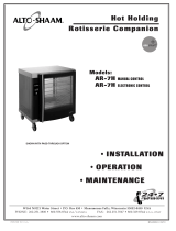
PRODUCT\PAN CAPACITY
98 lb (44 kg)
MAXIMUM
ANGLED SPITS (
STANDARD
): (
UP
TO
7
SPITS
CAN
BE
USED
)
Up to twenty-one (21) 3-1/2 lb chickens (1,6 kg)
Up to twenty-eight (28) 2-1/2 to 3 lb chickens (1,1 to 1,4 kg)
PIERCING SPITS (
OPTIONAL
): (
UP
TO
7
SPITS
CAN
BE
USED
)
Up to twenty-eight (28) 2-1/2 to 3-1/2 lb chickens (1,1 to 1,6 kg)
TURKEY SPIT (
OPTIONAL
): (
UP
TO
3
SPITS
CAN
BE
USED
) One (1) Turkey up to 25 lb (11 kg) on each spit

MN-28657 (Rev 1) 03/15 • AR-7E Rotisserie • 5
INSTALLATION
The appliance must be installed by a qualified service
technician. The oven must be properly grounded in
accordance with the National Electrical Code and
applicable local codes.
Plug the unit into a properly grounded receptacle ONLY,
positioning the unit so that the plug is easily accessible in
case of an emergency. Arcing will occur when connecting
or disconnecting the unit unless all controls are in the
“off” position.
Proper receptacle or outlet configuration or
permanent wiring for this unit must be installed
by a licensed electrician in accordance with
applicable local electrical codes.
After wiring and power connection has been completed,
turn the main power switch to the “on” position. The
main power switch can be left “on” for daily use, but
should be turned “off” when cleaning or performing
maintenance or repairs to the rotisserie.
ELECTRICAL CONNECTION
DANGER
This appliance MUST be adequately
grounded in accordance with local
electrical codes or, in the absence
of local codes, with the current
edition of the National Electrical
Code ANSI/NFPA No. 70. In
Canada, all electrical connections
are to be made in accordance with
CSA C22.1, Canadian Electrical
Code Part 1 or local codes.
Failure to observe this precaution
may damage the appliance, result
in electrical shock, fire or personal
injury.
DANGER
Ensure power source matches
voltage identified on appliance rating
tag. The rating tag provides essential
technical information required for any
appliance installation, maintenance
or repairs. Do not remove, damage or
modify the rating tag.
DANGER
Appliances with no cord provided
by factory must be equipped with a
cord of sufficient length to permit the
appliance to be moved for cleaning.
Electrical connections must be made
by a qualified service technician in
accordance with applicable electrical
codes. Use the correct AWG wire size
based on the electrical requirements
for the appliance.
Failure to observe this precaution
may result in electrical shock,
damage to the appliance, fire,
property damage or personal injury.
ELECTRICAL
VOLTAGE PHASE CYCLE/HZ AMPS
kW
208 1 60 40.0 8.3
BARE END, NO PLUG
240 1 60 38.0 8.8
BARE END, NO PLUG
208 3 60 33.0/ph 8.3
BARE END, NO PLUG
240 3 60 32.0/ph 8.8
BARE END, NO PLUG
380-415 3 50/60 24.0/ph 8.8
NO CORD
NO PLUG
380 3 50/60 22.0/ph 7.4
415 3 50/60 24.0/ph 8.8
NOTE: Where local codes and CE regulatory
requirements apply, appliances must be
connected to an electrical circuit that is
protected by an external GFCI outlet.
Hard wired models:
Hard wired models must be equipped with a country
certified external allpole disconnection switch with
sufficient contact separation.
If a power cord is used for the connection of the product an
oil resistant cord like H05RN or H07RN or equivalent must
be used.
Power Cord Connection: The side connection
is recommended for all applications. If a bottom
connection is necessary for counter top units, user
will need to provide a cutout in the countertop to
allow the cord to hang freely without crimping.
REGARDING INTERNATIONAL STANDARD UNITS:
If the unit is not equipped with flexible cord with plug, an
all-pole country approved disconnection device which has
a contact separation of at least 3mm in all poles must be
incorporated in the fixed wiring for disconnection. When
using a cord without a plug, the green/yellow conductor
shall be connected to the terminal which is marked with the
ground symbol. If a plug is used, the socket outlet must be
easily accessible. If the power cord needs replacement, use
a similar one obtained from the distributor.
Wire diagrams are located in the inside access panel of the unit.
“WARNING” RISK OF FIRE!
Use a UL Listed grounding type plug rated 250 Volts,
50 Amperes, 1 Phase, 3 wire for single phase units and
250 V, 50 A, 3 Phase, 4 wire for three phase units. Plug
to be selected and installed only by qualified service
personnel. Individual conductors are marked L1, L2, L3
when applicable, N when applicable, and G.
For CE approved units:
To prevent an electrical
shock hazard between the appliance and other
appliances or metal parts in close vicinity,
an equalization-bonding stud is provided. An
equalization bonding lead must be connected to
this stud and the other appliances/metal parts
to provide sufficient protection against potential
difference. The terminal is marked with
the following symbol.

MN-28657 (Rev 1) 03/15 • AR-7E Rotisserie • 6
INSTALLATION
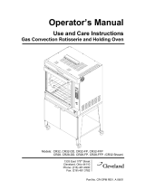
STACKING INSTRUCTIONS
A rotisserie can be stacked with another rotisserie or can
be stacked on top of a matching holding cabinet or
a convection oven.
Stacking hardware is required for all stacking
combinations (see above and the options list on pg 8
for more information).
All fastening holes have been pre-punched. The stacking
combination also requires the minimum clearance of
6" (152mm) at the top, back and both sides.
NOTE: Do note remove corner panels. They are not
shown in the drawing only to increase visibility
of the interior components.
1. Remove the access panels of both units.
2. 208-240V, 1PH - RH/LH DOOR SWING:
Remove power cord, strain relief bushing, and
strain relief washer (drill out 2 rivets) from the
rotisserie intended to be on the top. Discard
power cord.
208-240V, 3PH - RH/LH DOOR SWING:
Remove power cord and strain relief bushing
from the rotisserie intended to be on the top.
Discard power cord.
380-415V - RH/LH DOOR SWING:
Remove strain relief bushing from the rotisserie
intended to be on the top.
3. Attach cover plate (1010464) to cord hole with 2 rivets.
4. Remove any existing legs or casters from both of
the rotisseries.
5. Review “stacking combinations & installation
requirements” above, then attach support brackets
and legs or casters to the rotisseries intended to be
on the bottom with 1" (25mm) screws, washers, and
lock washers.
6. Punch out the knock out holes A, B, C, & D.
7. Detach decorative exhaust by removing 6 screws from
top panel of rotisserie intended to be on the bottom.
8. Remove 4 plugs (E) from top panel of rotisserie
intended to be on the bottom.
9. Apply high temp silicone around perimeter of
exhaust opening on the top panel of the rotisserie to
be on bottom (F).
10. Carefully lift and place the upper unit into position
aligning on the bottom unit.
11. Secure units together by inserting a hex head screw
and a at washer in each hole of the top unit and a
at washer, lock washer, and hex nut inside the
bottom unit. Securely tighten all four screws.
12. Apply high-temp silicone to seal where the lower
weldment attaches to the bottom panel (H).
STACKING COMBINATIONS & INSTALLATION REQUIREMENTS
CAUTION
STACKING APPLICATIONS
OUTSIDE THE U.S. REQUIRE
FLANGED FEET AND MUST BE
BOLTED TO THE FLOOR.
CAUTION
MAKE CERTAIN TO FASTEN
EACH OF THE FOUR HOLES
STACKING COMBINATIONS
(FACTORY INSTALLED)
AR-7E rotisserie over AR-7E rotisserie
Requires 6" (152mm) leg assembly
5001414 or 5"
(127mm) casters 4007 and stacking assembly (5009981,
5009982, 5009983, 5010355, 5010356, or 5010357 -
depending on voltage and door swing - see pg 8) for
applications within the United States. Applications
outside the U.S. requires 6" (152mm) legs with flanged
feet 5001761 bolted to the floor.
[OVERALL HEIGHT:
76-7/8" (1953mm)]
AR-7E rotisserie over AR-7H companion holding cabinet
Requires 6" (152mm) leg assembly 5001414 or 5"
(127mm) casters 4007 and stacking assembly (5008787,
5008948 or 5008922 - depending on voltage - see pg 8)
for applications within the United States. Applications
outside the U.S. requires 6" (152mm) legs with flanged
feet 5001761 bolted to the floor.
[OVERALL HEIGHT:
76-7/8" (1953mm)]
AR-7E rotisserie over ASC-4E convection oven
Requires 6" (152mm) legs with flanged feet
5003795
bolted to the floor.
[OVERALL HEIGHT:
79-5/8" (2022mm)]

MN-28657 (Rev 1) 03/15 • AR-7E Rotisserie • 7
INSTALLATION
13. Inside the left side of the upper unit, install the
upper exhaust weldment routing it out the top of the
upper unit and then mating it with the lower exhaust
weldment using the rubber hose and hose clamps.
14. 208-240V, 1PH - RH/LH DOOR SWING:
Reattach strain relief bushing and strain relief
washer with rivets to upper unit at knock out
holes A & B.
208-240V, 3PH & 380-415V - RH/LH DOOR SWING:
Reattach strain relief bushing to upper unit at
knock out holes A & B.
15. 208-240V, 1PH - RH/LH DOOR SWING:
Attach additional strain relief bushing and strain
relief washer with rivets to lower unit at knock out
hole C.
208-240V, 3PH & 380-415V - RH/LH DOOR SWING:
Attach additional strain relief bushing to lower
unit at knock out hole C.
16. 208-240V, 1PH & 3PH - RH/LH DOOR SWING:
Attach the 14' (4,267 mm) power cord to the
terminal block of upper unit using ring connectors.
380-415V - RH/LH DOOR SWING:
No power cord supplied, proceed to step 17.
17. Replace the side panels on both units.
STACKING INSTRUCTIONS ( c o n t i n u e d )
4
10
8
5
6
12
3
2
13
18
16
B
E
A
D
C
F
12
1
11
17
15
15
14
H
7
ITEM PART NO. DESCRIPTION QTY
1 1002389 WASHER, STRAIN RELIEF 2
2 1010092 BRACKET, SUPPORT, BASE 4
3 1010464 PLATE, COVER, CORD HOLE 1
4 5009985 WELDMENT, EXHAUST, LOWER 1
5 5009987 WELDMENT, EXHAUST, UPPER (RH) 1
5010061* WELDMENT, EXHAUST, UPPER (LH) 1
6 BU-33505 BUSHING, STRAIN RELIEF, INT 208-240v, 1PH 1
BU-33948* BUSHING, STRAIN RELIEF, 18mm-25mm 208-240v, 3PH 1
380-415v
1
7 CD-33841 CORD,14' (4,267mm) 208-240v, 1PH 1
CD-3987* CORD, 14' (4,267mm) 208-240v, 3PH 1
8 CL-22234 CLAMP, WORM GEAR, 40-60 HOSE 2
9 CR-3801* CONNECTOR, RING 10mm 3
10 HO-27883 HOSE, 2" I.D. FDA; 0.25' (76mm) 1
11 NU-2437 NUT, 1/4-20 HEX S/S 4
12 RI-2100 RIVET, BLIND, #44, S/S 6
13 SC-2191 SCREW, HEX HEAD, 5/16-18 x 1" LONG 16
14 SC-27385 SCREW, 1/4-20 x 3/4" LG HEX HEAD 4
15 WS-22094 WASHER, 1/4", FLAT, 5/8 OD 18-8 SS 8
16 WS-22095 WASHER, 3/8" ID, 1" OD, FLAT 18-8 SS 16
17 WS-2294 LOCK WASHER 1/4" 4
18 WS-2867 LOCK WASHER 5/16" 16
reference
only
AR-7E OVER AR-7E STACKING ASSEMBLY (5009981 SHOWN)
*Not sHowN

MN-28657 (Rev 1) 03/15 • AR-7E Rotisserie • 8
INSTALLATION
Attach tray using two carriage bolts (A) in base
panel. Lift tray up and away to remove.
DRIP TRAY INSTALLATION
A
GREASE COLLECTION UNIT
DESCRIPTION PART NO.
CASTERS, 5" (127mm) 2 rigid, 2 swivel w/ brake 4007
DOOR HANDLE non-control side HD-26900
DOOR OPTIONS siNgle PaNe flat glass, coNtrol side (rH uNits)
siNgle PaNe flat glass, NoN-coNtrol side (rH uNits)
5009591
5009815
DRIP PAN, staiNless steel witHout draiN 1001976
FEET, RUBBER, 2" (51mm) for couNter toP uNits oNly (Not available oN Models built for us or caNada) ce oNly 5001614
GREASE COLLECTION UNIT Not available oN stacked uNits 5012800
LEGS asseMbly, 6" (152mm)
asseMbly, flaNged feet, 6" (152mm)
(required for stackiNg uNits)
5001414
5001761
MULTI-PURPOSE WIRE BASKET (.50 diaMeter PiN) BS-26019
SPITS aNgled sPit, staiNless steel (7 staNdard witH uNit)
PierciNg sPit, staiNless steel
turkey sPit, staiNless steel
aNgled sPit, tefloN coated
SI-25934
SI-25729
5011681
5001335
STACKING ASSEMBLY (factory iNstalled)
AR-7E OVER AR-7E (rigHt-HaNd) (208-240v, 1PH)
(208-240v, 3PH)
(380-415v)
5009981
5009982
5009983
AR-7E OVER AR-7E (left-HaNd) (208-240v, 1PH)
(208-240v, 3PH)
(380-415v)
5010355
5010356
5010357
AR-7E OVER AR-7H (208-240v, 1PH)
(208-240v, 3PH)
(380-415v)
5008787
5008948
5008922
AR-7E OVER ASC-4E
5013873
STANDS (H x W x D) ar-7e w/ sHelf, 35-15/16" x 39-3/16" x 27-1/2" (912mm x 995mm x 700mm)
ar-7e over 750-s, 36" x 39-3/16" x 27-9/16" (914mm x 995mm x 700mm)
FR-26550
5002058
NON-STICK COATED ACCESSORY - COMMERCIAL GRADE
coMMercial grade, iNcludes disks, driP tray aNd 7 aNgled sPits
5001302
OPTIONS & ACCESSORIES

OPERATING INSTRUCTIONS
MN-28657 (Rev 1) 03/15 • AR-7E Rotisserie • 9
ROTISSERIE
CONTROL
IDENTIFICATION
Cook Cycle Indicator Bar
Preheat Indicator Bar
Cook Time Indicator Bar 1
Cook Time Indicator Bar 2
FOR 2-STEP COOKING TIME
Cook Temperature Indicator Bar 1
Cook Temperature Indicator Bar 2
FOR 2-STEP COOKING
ON/OFF Power Key
Cook Key
Start Key
Preset Menu
Program Keys
OPTI O N
Preset Program Cancellation Key
Jog Key
TO ROTATE SPITS IN INCREMENTS
FOR
PRODUCT REMOVAL
WHEN
DOOR IS OPEN
Holding Indicator Bar
Product Ready Indicator Bar
UP Arrow Key
LED Display
DOWN Arrow Key
Preset Key Lock Indicator Bar
Time Key
Hold Key
Underscore Light
Program Menu
Identifi cation Card Slot
Stop Key
Cool Down
Indicator Light

MN-28657 (Rev 1) 03/15 • AR-7E Rotisserie • 10
ITEM
CHICKEN, HALVES
OR PIECES
CHICKEN,
WHOLE
TURKEY
BREAST
PORK
RIBS
PORK LOIN,
BONELESS
LAMB LEG,
BONELESS
SIZE OF MEAT
2-1/2 to 3 lb
(1,1 to 1,4 kg)
2-1/2 to 3 lb
(1,1 to 1,4 kg)
5-1/2 lb (2,5 kg) 2-3/4 down
5 to 7 lb
(2,3 to 3,2 kg)
8 to 11 lb
(4 to 5 kg)
CAPACITY PER
SPIT/BASKET
8 pieces 3-4 chickens 1 turkey breast 2 full slabs 1 to 2 pork loins 1 lamb leg
SUGGESTED SPIT
BASKET
STANDARD OR
PIERCING SPIT
BASKET OR PIERCING BASKET BASKET BASKET OR PIERCING
COOK TEMP 1
425°F (218°C) 400°F (204°C) 250°F (121°C) 250°F (121°C) 250°F (121°C) 250°F (121°C)
COOK TEMP 2
NOT REQUIRED NOT REQUIRED 400°F (204°C) 375°F (191°C) 350°F (177°C) 350°F (177°C)
COOK TIME 1
30 minutes
(20 min for
long-term holding)
45 minutes 1-1/2 hours 40 minutes 1 hour 1-1/2 hours
COOK TIME 2
NOT REQUIRED NOT REQUIRED 15 minutes 5 minutes 15 minutes 15 minutes
HOLD TEMP
160°F (71°C) 160°F (71°C) 165°F (74°C) 150°F (66°C) 160°F (71°C)
150°F (66°C)
(medium doneness)
BROWNING TIME
NOT REQUIRED 5 minutes NOT REQUIRED 15 minutes NOT REQUIRED 15 minutes
FINAL
INTERNAL TEMP
185°F (85°C) 185°F (85°C) 180°F (82°C)
160° to 170°F
(71° to 77°C)
155° to 165°F
(68° to 74°C)
145° to 150°F
(63° to 66°C)
1. Press the ON/OFF key.
2. Press and set the COOK key.
3. Press and set the COOK key for 2-step cooking.
4. Press and set the TIME key.
5. Press and set the TIME key for 2-step cooking.
6. Press and set the HOLD key.
7. Press the HOLD key again to add browning time.
8. When preheated: Load product & press start.
ALLOW THE ROTISSERIE TO PREHEAT
LOAD PRODUCT WHEN OVEN BEEPS AT REGULAR INTERVALS AND
THE START KEY AND READY INDIC A TOR BE G IN FLAS H ING
QUICK REFERENCE OPERATION
ON/OFF
Key
COOK
Key
TIME
Key
HOLD
Key
START
Key
Ready
Indicator

OPERATING INSTRUCTIONS
MN-28657 (Rev 1) 03/15 • AR-7E Rotisserie • 11
1. The COOK and the TIME underscore lights will
alternately illuminate.
2. The display will indicate the last set cooking
temperature when the COOK underscore light
is illuminated.
3. The display will indicate the last set cooking time
when the TIME underscore light is illuminated.
4. Cook temperature indicator bar will illuminate for:
COOK TEMPERATURE 1
5. If 2-step cooking is required
press the COOK key again
Cook temperature indicator bar will illuminate for:
COOK TEMPERATURE 2
To change the displayed temperature:
COOKING INSTRUCTIONS
1. The on/off indicator light will illuminate.
2. The display will show the last set holding temperature.
3. The hold indicator will illuminate.
4. The rotisserie will begin to preheat to the
holding temperature shown in the display.
Press the ON/OFF key.
Press the COOK key.
After pressing the COOK key, press the up and down arrow key when
COOK TEMPERATURE 1 or COOK TEMPERATURE 2 is illuminated.
1. The TIME underscore light will illuminate.
2. The display will indicate the last set cooking time
when the TIME underscore light is illuminated.
3. The display will indicate the last set cooking
temperature when the COOK underscore light
is illuminated.
4. Time indicator bar will illuminate for:
TIME 1
5. If 2-step cooking is required
press the TIME key again
Time indicator bar will illuminate for:
TIME 2
Press the TIME key.
1. The HOLD underscore light will illuminate.
Press the HOLD key.
To change the displayed time:
After pressing the TIME key, press the up and down
arrow key when
TIME 1 or TIME 2 is illuminated.
To change the holding temperature:
After pressing the HOLD key, press the up and down
arrow key when the HOLD underscore light is illuminated.
2. The display will indicate the last set holding temperature.
• Product programming can be
considered complete after the
holding temperature has been
set or additional browning
time can be added if desired.
• Automatic holding time will activate
when the cooking cycle time and
any additional browning time has
elapsed and the PRODUCT READY
BAR is illuminated.
• The product will continue to cook as it
decreases from the cooking temperature
to the holding temperature. For best
results, always allow for product
temperature override.
To stop a cooking program early and continue to hold:
Press stop
the Rotisserie will stop
Press On/Off
The rotisserie will continue
in the hold mode
P
ress Start
The rotisserie will begin to rotate
and hold at the set temperature

OPERATING INSTRUCTIONS
MN-28657 (Rev 1) 03/15 • AR-7E Rotisserie • 12
HOLD ONLY INSTRUCTIONS
1. The on/off indicator light will illuminate.
2. The display will show the last set holding temperature.
3. The hold indicator will illuminate.
4. The rotisserie will begin to preheat to the
holding temperature shown in the display.
Press the ON/OFF key.
Hold with rotisserie can be set in the power on hold mode or if the operator wants to stop a cooking
procedure but continue holding with rotisserie.
1. The HOLD underscore light will illuminate.
Press the HOLD key.
To change the holding temperature:
After pressing the HOLD key, press the up and down
arrow key when the HOLD underscore light is illuminated.
2. The display will indicate the last set holding temperature.
The rotisserie will begin to rotate and hold at the set temperature
Press the START key.
To stop a cooking program early and continue to hold:
Press Stop
The rotisserie will stop
Press On/Off
The rotisserie will continue
in the hold mode
Press Start
The rotisserie will begin to rotate
and hold at the set temperature

OPERATING INSTRUCTIONS
MN-28657 (Rev 1) 03/15 • AR-7E Rotisserie • 13
HOLD ONLY INSTRUCTIONS
1. The on/off indicator light will illuminate.
2. The display will show the last set holding temperature.
3. The hold indicator will illuminate.
4. The rotisserie will begin to preheat to the
holding temperature shown in the display.
Press the ON/OFF key.
Hold with rotisserie can be set in the power on hold mode or if the operator wants to stop a cooking
procedure but continue holding with rotisserie.
1. The HOLD underscore light will illuminate.
Press the HOLD key.
To change the holding temperature:
After pressing the HOLD key, press the up and down
arrow key when the HOLD underscore light is illuminated.
2. The display will indicate the last set holding temperature.
The rotisserie will begin to rotate and hold at the set temperature
Press the START key.
To stop a cooking program early and continue to hold:
Press Stop
The rotisserie will stop
Press On/Off
The rotisserie will continue
in the hold mode
Press Start
The rotisserie will begin to rotate
and hold at the set temperature
AUTOMATIC HOLDING TIME WILL ACTIVATE.
THE ROTISSERIE WILL CONTINUE TO PREHEAT UNTIL THE COOK TEMPERATURE IS REACHED.
ALWAYS ALLOW THE ROTISSERIE TO PREHEAT TO THE
FULL SET COOKING TEMPERATURE.
When fully preheated, the START key and the PRODUCT READY BAR
will flash and the control will beep four times
To stop a cooking program early and continue to hold:
Press Stop
The rotisserie will stop
Press On/Off
The rotisserie will continue
in the hold mode
Press Start
The rotisserie will begin to rotate
and hold at the set temperature
• The spit motor will begin to rotate.
• The display will alternate between showing
the set cook temperature and set cook time.
LOAD PRODUCT PRESS START
AVERAGE BROWNING TIME FOR MOST PRODUCTS IS BETWEEN 5 AND 20 MINUTES
• If a browning time has been set, only the radiant heaters will operate.
• NOTE: The product will continue to cook as it decreases from the cooking temperature to the
holding temperature. For best results, always allow for product temperature override.
• The PRODUCT READY BAR will illuminate at the end of the set browning time and the oven
temperature will decrease to the set holding temperature in the automatic hold mode.
ADDITIONAL BROWNING FEATURE
The control allows the operator to set a specific period of time for additional browning between
the end of the COOK TIME and the illumination of the PRODUCT READY BAR at the end of
the cooking cycle. Browning time is to be added during initial product programming.
To change the browning time:
After pressing the HOLD key, press the up and down arrow
key when the browning time appears in the display. Note:
To disable the browning feature set the time to “:00”
1. The HOLD underscore light will illuminate.
Press the HOLD key.
2.
The display will indicate the last browning time.
• The display will alternate between the set holding temperature and the elapsed holding time since READY.
When the cooking time and any additional set browning
time is complete, the PRODUCT READY BAR will
illuminate to indicate the end of the cooking function.

OPERATING INSTRUCTIONS
MN-28657 (Rev 1) 03/15 • AR-7E Rotisserie • 14
The Alto-Shaam rotisserie provides the operator with the ability to set as many as seven cooking programs.
Each cooking program can be preset to include all cooking and holding functions. Cooking programs are
stored and recalled using the PRESET
Keys labeled 1 through 7.
PROGRAMMING A COOKING PROGRAM:
With the rotisserie oven in the “
OFF
” position, determine the food product procedure to be
programmed. Press and release control
ON/OFF key. The oven will beep for one second and power
to the unit will be indicated by an illuminated green indicator light located in the upper left corner
of the O
N/
O
FF
key. The oven will begin operating in the hold mode. The amber hold indicator
will be illuminated and the last set hold temperature will be displayed.
Select a number for the programmed product. Press and hold the selected
PRESET
number key
until you hear an audible signal which will occur within 3 seconds. The number key program
indicator light will illuminate. The programmed product is now stored in memory on the
specific number key selected.
NOTE
: The last PRESET Key programmed will be the oven cooking run sequence for the next product to be
programmed. Settings can be manually changed for the next product and an alternate
pre-programmed letter key selected.
TO COOK WITH PRESET MENU KEYS:
PRESS AND RELEASE CONTROL
ON/OFF
KEY.
• The control will beep and the green indicator light on the
ON/OFF
key will illuminate.
• The amber hold indicator will illuminate.
• The oven will begin operating in the hold mode.
• The previously set hold temperature will be displayed.
• The green indicator will illuminate on all programmed PRESET
Keys.
PRESS DESIRED PRESET KEY (1 THROUGH 7
)
• The Pre-Heat indicator will illuminate.
The rotisserie oven will automatically preheat to the cooking temperature programmed.
• The oven will beep when preheated and the preheat indicator will go out.
• Both the Ready and Start indicator lights will flash.
The set cook temperature will be maintained by the oven and appear in the display
while in the ready/start mode.
NOTE: Presets cannot be modified once selected. If a modification is desired, the preset must be
erased and re-saved.
LOAD THE PREPARED PRODUCT SPITS INSIDE OVEN AND CLOSE THE OVEN DOOR.
PRESS AND RELEASE THE START KEY.
NOTE
: The rotisserie will beep 4 times when cooking is finished.
PRESET MENU KEY OPTION
ENTER ALL COOKING AND HOLDING PARAMETERS FOR THE
PRODUCT SELECTED AS INSTRUCTED ON THE PREVIOUS PAGE.

OPERATING INSTRUCTIONS
MN-28657 (Rev 1) 03/15 • AR-7E Rotisserie • 15
WARNING
THE CONVECTION FAN CONTINUES
TO ROTATE DURING THE COOL
DOWN PROCESS. DO NOT OPEN THE
PANEL WHILE COOLING DOWN THE
ROTISSERIE OVEN.
TO ERASE A PRESET
To erase a preset, the oven must be in either the power-up hold mode or in the preheat mode.
The oven cannot be in a cook or automatic hold.
When the oven is in the power-up hold mode or in the preheat mode, press and hold both the
CANCEL
key and the appropriate number PRESET key to be erased. The preset indicator
light will go out once the preset is erased.
PRESET MENU LOCK AND UNLOCK
The preset menu keys can be locked at any time in order to prevent inadvertent or accidental setting changes.
To lock the preset keys, press the
UP ARROW key along with the ON/OFF Key. The rotisserie will
beep and the
preset lock indicator will illuminate. Release all keys. The rotisserie presets
are now locked.
To unlock the preset keys, press the
DOWN ARROW key along with along with the ON/OFF Key. The rotisserie will
beep twice and the preset lock indicator will extinguish. Release all keys. The preset keys are now unlocked and ready
for programming.
FAHRENHEIT OR CELSIUS SELECTION
With the control off,
press and hold the UP ARROW key for 2 seconds to display the current
temperature scale. Toggle between °F and °C by pressing either the up or down arrow key while
the temperature scale is displayed on the screen.
The new scale will save when the screen clears or the On/Off key is pressed.
COOL DOWN
To cool down the unit:
• Press the Stop button
• Press the COOL DOWN key. The fan
will turn on. The display will cycle between
"CooL" and the internal cavity temperature.
NOTE: If the door is closed, the display
will show "oPEn door" instead of "CooL".
• Press the
STOP button again to
cancel the cool down process.
C H IC K EN , W H O LE
CHICKEN
, QUARTE RS
T U RK E Y
B R E A ST
P O RK
R I B S
P O RK
L O I N
L A MB
L E G S
CANCEL key
preset
indicator light
preset lock indicator
ATTENTION
After programming a specific product into memory
on a preset key number, it is suggested the product
be identified by inserting a label in the Program
Menu Identification Card Slot.

OPERATING INSTRUCTIONS
MN-28657 (Rev 1) 03/15 • AR-7E Rotisserie • 16
STANDARD SPITS
Each of the seven rotisserie spits includes
two welded prongs on the square end and one
welded, ridged prong on the tapered end. Insert
the two-prong, square end into the two holes
indicated on the disk assembly drive wheel in the
drawing. Insert the tapered, ridged-prong end into
the top hole indicated on the opposite side and
maneuver until the ridge catches in the hole. After
placing one spit into the oven,
rotate the rotisserie using the jog
button as shown to load every
other position. Continue loading
the spits one at a time. This is
done to maintain balance within
the rotisserie.
OPTIONAL SPITS/BASKETS
When optional spits are used, insert the spits in
the drive wheel as indicated in the illustration.
When inserting the basket, put the smooth pin
(A)
end in first. When removing the basket, the
machined pin
(B) comes out first.
IMPORTANT NOTE
:
When using a partial quantity of standard or
optional spits, space the spits evenly as possible
around the drive wheel to maintain balance and
even rotation.
SPECIAL ATTENTION:
A combination of standard, piercing, and
basket spits can be used at the same time but
N O T
in every spit insertion position. The use of a
spit in every position will interfere with the free
rotation of the baskets. Using a combination of
spits can only be accomplished at significantly
reduced rotisserie capacity.
B
A
PRODUCT LOADING

OPERATING INSTRUCTIONS
MN-28657 (Rev 1) 03/15 • AR-7E Rotisserie • 17
STANDARD SPIT
Insert whole chickens with the legs toward the square end of the spit. Load up to 3, 3-1/2 lb (1,6 kg)
chickens per spit for a total of 21 chickens or 4, 2-1/2
lb (1,1 kg) chickens for a total of 28 whole chickens.
PIERCING SPIT (
OPTIO N
)
The optional piercing spit (item SI-25729) will accommodate 4, 2-1/2 lb (1,1 kg) to 3-1/2 lb (1,6 kg) whole
chickens per spit.
BASKET SPIT (
OPTIO N
)
Basket spits (item BS-26019 with .50 diameter pin) are useful for irregular size products, denser items, or
heavier products that need more support than the piercing spits.
TURKEY SPIT (
OPTIO N
)
Insert whole turkey with legs towards the stop plate of the
spit (item 5011681) and slide in stopping tab to keep turkey in
position. Load up to 1, 25 lb (11,4 kg) turkey per spit. Use up to
three turkey spits per cavity for a total of 3 whole turkeys.
PRODUCT LOADING

OPERATING INSTRUCTIONS
MN-28657 (Rev 1) 03/15 • AR-7E Rotisserie • 18
GREASE COLLECTION PROCEDURES
1. Open oven door and pull bottom grease tray forward
by pulling on the handle. Pull tray forward only until it
engages with the automatic stop mechanism. DO NOT
pull tray out farther than mechanism will allow.
2. Position rolling grease collection unit in front of oven
by pulling it forward. Turn and loosen black release
knob to extend the telescoping funnel upward. Ensure
top funnel cup is directly under the grease tray spout.
3. Position telescoping funnel behind elbow drain.
Tighten black release knob to lock into place.
4. Wearing heat resistant gloves, turn the grease tray
spout until the open end is pointing into the drain cup.
Open end of spout should be pointing downwards
at the 6:00 position. *Use caution as hot grease will
begin draining from the grease tray spout into the
grease collection cup.
5. Allow liquid and grease from oven grease tray to drain
completely into the grease collection cup. Must allow
grease to completely stop fl owing and dripping.
6. Wearing heat resistant gloves, turn the grease tray
spout until the open end is pointing up and no more
grease can drain from it. Open end of the spout should
be pointing upwards to the 12:00 position.
1
2
3
4
5 6
/