Page is loading ...


Build 31 v31.6.16 Beta
JUNE 22, 2011 © 2007-2011 RED.COM INC.
1
TABLE OF CONTENTS
DISCLAIMER ..................................... 3
Copyright Notice ............................ 3
Trademark Disclaimer .................... 3
Compliance .................................... 3
Industrial Canada
Emission Compliance
Statements ................................ 3
Federal Communications
Commission (FCC)
Statement .................................. 3
Australia and New
Zealand Statement .................... 4
Japan Statements ..................... 4
European Union
Compliance Statements ............ 4
BEFORE YOU START ....................... 5
Important Safety Instructions ........ 5
THEORY OF OPERATION ................. 8
MYSTERIUM® Sensor................... 8
MYSTERIUM X® Sensor ............... 8
Image Processing .......................... 9
Audio Recording ............................ 9
Line Level Inputs ............................ 9
Microphone Level Inputs ............... 9
Video Monitoring Outputs ............ 10
RED EVF / BOMB EVF /
RED LCD ................................. 11
Record Indicator .......................... 12
Recording Errors ..................... 12
Master / Slave Camera
Configuration ............................... 13
Digital Magazines ........................ 13
Metadata ................................. 13
Clip Naming Conventions ....... 13
Power Consumption .................... 15
CAMERA CONTROLS,
CONNECTORS AND
DISPLAYS ........................................ 16
Camera Controls .......................... 16
Left Front of Camera ............... 16
Rear of Camera ....................... 17
Joystick Operation .................. 19
Power On / Off switch ............. 20
Camera Connectors..................... 21
Right Side of Camera .............. 21
Rear of Camera ....................... 22
Camera Displays .......................... 23
Camera LCD Status
Display .................................... 23
RED EVF.................................. 24
BOMB EVF .............................. 25
RED LCD ................................. 26
External HD-SDI or HDMI
Monitors .................................. 26
RED LCD / RED EVF /
HD-SDI / HDMI Display
Elements .................................. 27
BASIC OPERATION ......................... 29
Power Up / Down ......................... 29
Operating Camera using
RED Charger ................................ 30
Recharging Batteries using
RED Charger ................................ 30
First Time Use - Setting Up
Your RED ONE ............................. 31
Master / Slave Camera
Configuration ........................... 31
Connecting Media ........................ 32
Project Setup ............................... 33
Resolution ................................ 33
Time Base ................................ 34
Quality ..................................... 34
Recording ..................................... 34
Playback....................................... 35
Back Focus Adjustment ............... 36
SENSOR MENU CONTROLS .......... 38
Sensitivity ..................................... 38
ISO Rating ............................... 38
Color Temp .................................. 39
Auto WB .................................. 39
Tungsten .................................. 39
Daylight .................................... 39
Manual WB .............................. 39
Trim ......................................... 40
Shutter Menu................................ 42
Genlock ................................... 42
Mode ....................................... 43
Speed ...................................... 43
Syncro ..................................... 44
Phase ....................................... 44
Varispeed ..................................... 45
Varispeed ................................. 46
Ramp ....................................... 46
Frame Rate .............................. 46
Time ......................................... 48
End Rate .................................. 48
Time-Lapse .................................. 48
Enable ...................................... 49
Speed ...................................... 49
Step Print ................................. 50
Interval ..................................... 50
Burst Type ............................... 50
AUDIO / VIDEO MENU
CONTROLS ...................................... 51
View.............................................. 51
RAW......................................... 51
REDcolor ................................. 51
Video ............................................ 51
Look ......................................... 52
Color ....................................... 53
Gain ......................................... 54
Tone ........................................ 55
Flut .......................................... 56
Viewfinder Menu .......................... 56
False Color (Previously
Color) ...................................... 56
Meter ....................................... 59
Assists ..................................... 63
Zebras ..................................... 66
Intensity (Previously Dark
Detail) ...................................... 69
Open Gate ............................... 69
Audio ........................................... 69
Line Level Inputs ..................... 70
Microphone Level Inputs ......... 70
Headphone .................................. 70
Volume (Master) ...................... 71
Volume Left ............................. 71
Volume Right ........................... 71
Mix .......................................... 71
SYSTEM MENU CONTROLS .......... 72
Sound .......................................... 72
REC Enable ............................. 72
Output Level ............................ 72
48V MIC .................................. 73
Media ........................................... 73
Pre-Record .............................. 73
Unmount ................................. 75
Format ..................................... 75
Change .................................... 75
Reset ....................................... 76
Project ......................................... 76
Status ...................................... 77
Slate ........................................ 78
Configure ................................ 79
Timecode ................................ 82
QT Proxies .............................. 84
Monitor ........................................ 84
Frame Guide ........................... 85
Preview ................................... 89
Test Signal .............................. 89
PVW Refresh (Formerly
HD-SDI) ................................... 91
EVF Refresh ............................ 91
Setup ........................................... 92
Preferences ............................. 92
Maintenance ......................... 101
Setting System Clock ............ 107
Remote.................................. 109
Program ................................ 110
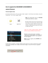
APPENDIX A: UPGRADING
CAMERA FIRMWARE ................... 114
Verify Current Camera
Firmware .................................... 115

Build 31 v31.6.16 Beta
© 2007-2011 RED.COM INC. JUNE 22, 2011
2 2
Upgrade Procedure ................... 115
APPENDIX B: MANAGING
DIGITAL MEDIA ............................. 118
Media types ............................... 118
Formatting Media ...................... 118
Re-formatting Media .................. 121
Media Capacity Remaining
Status ........................................ 122
Remove Media from Camera
(Unmount) .................................. 122
Procedure A .......................... 123
Procedure B .......................... 123
Procedure C .......................... 124
Copying Media .......................... 124
Erasing Media Using
Macintosh OS X ......................... 124
Erasing Media Using
Windows .................................... 125
SD Memory Card / USB
Memory Devices ........................ 125
SD Memory Card .................. 125
USB Memory Device ............. 125
APPENDIX C: SAVING LOOK /
USER PROFILE ............................. 126
Look ........................................... 126
Export Look ........................... 126
Import Look ........................... 127
User Profile ................................ 127
Export User Profile ................ 127
Import User Profile ................ 128
Data Not Saved During
Export ......................................... 128
APPENDIX D: INPUT /
OUTPUT CONNECTORS ............... 129
Right Side of Camera ................. 129
Timecode Input / Output ....... 129
Aux / RS232 Port ................... 130
Viewfinder (RED EVF)
Interface ................................. 131
Monitor (RED LCD)
Interface ................................. 131
Line Level / Microphone
Level Audio Inputs ................. 131
Line Audio Output .................. 133
Headphone Audio Output ...... 133
USB-2 Master ........................ 134
USB-2 Slave .......................... 134
Genlock Input ........................ 135
Program (Dual-link) HD-
SDI ......................................... 135
Preview HD-SDI ..................... 136
HDMI ..................................... 136
Rear of Camera .......................... 137
DC Power Input ..................... 138
Drive Interface ....................... 138
Auxiliary Power Outputs ........ 139
APPENDIX E: MASTER /
SLAVE CAMERA
CONFIGURATION .......................... 140
Preparation ................................. 140
Connecting ................................ 141
Jam SYNC ............................ 141
Genlock ................................. 142
Operation ................................... 142
Setup ..................................... 142
Formtatting Media ................. 143
Recording .............................. 143
Clip Naming Conventions .......... 143
Camera Position / Slate /
Camera ID ............................. 143
APPENDIX F: EXPOSURE
TIPS – USING FALSE COLOR
AND ISO ......................................... 145
Underexposure (~ 2 stops) ........ 145
Overexposure (~ 2 stops) .......... 147
Appropriate Exposure ................ 149
Adjusting the ISO Rating ........... 151
APPENDIX G: POST
PRODUCTION ............................... 153
Software Tools ........................... 153
RED QuickTimecodec ........... 154
REDCINE-X® ........................ 155
APPENDIX H: POSSIBLE
ERRORS, ISSUES AND
SOLUTIONS ................................... 156
APPENDIX I: ACCESSORY
OPTIONS ....................................... 160
APPENDIX J: MENU MAPS .......... 161
RED ONE® Operation Guide
Camera Build 31 Version 31.6.16 Beta
June 22, 2011

Build 31 v31.6.16 Beta
JUNE 22, 2011 © 2007-2011 RED.COM INC.
3
DISCLAIMER
RED® has made every effort to provide clear and accurate information in this Operation Guide, which is
provided solely for the user’s information. While thought to be accurate, the information in this document
is provided strictly “as is” and RED will not be held responsible for issues arising from typographical errors
or user’s interpretation of the language used herein that is different from that intended by RED. All safety
and general information is subject to change as a result of changes in local, federal or other applicable
laws.
RED reserves the right to revise this Operation Guide and make changes from time to time in the content
hereof without obligation to notify any person of such revisions or changes. In no event shall RED, its em-
ployees or authorized agents be liable to you for any damages or losses, direct or indirect, arising from
the use of any technical or operational information contained in this document.
COPYRIGHT NOTICE
© 2011 Red.com, Inc.
All trademarks, trade names, logos, icons, images, written material, code, and product names used in as-
sociation with the accompanying product are the copyrights, trademarks or other intellectual property
owned and controlled exclusively by Red.com, Inc.
TRADEMARK DISCLAIMER
All other company, brand and product names are trademarks or registered trademarks of their respective
holders. RED has no affiliation to, is not associated or sponsored with, and has no express rights in third-
party trademarks. MAC® and QuickTime® are registered trademarks of Apple, Inc. Intel® is the regis-
tered trademark of Intel Corporation. Windows®, Microsoft Windows® and Windows Vista® are the reg-
istered trademarks of Microsoft Corporation. AVID® is a registered trademark of Avid Technology, Inc.
COMPLIANCE
INDUSTRIAL CANADA EMISSION COMPLIANCE STATEMENTS
This Class A digital apparatus complies with Canadian ICES-003.
Cet appareil numérique de la classe A est conforme à la norme NMB-003 du Canada.
FEDERAL COMMUNICATIONS COMMISSION (FCC) STATEMENT
This equipment has been tested and found to comply with the limits for a Class A digital
device, pursuant to part 15 of the FCC Rules. These limits are designed to provide rea-
sonable protection against harmful interference when the equipment is operated in a
commercial environment. This equipment generates, uses, and can radiate radio frequen-
cy energy and, if not installed and used in accordance with the instruction manual, may
cause harmful interference to radio communications. Operation of this equipment in a residential area is
likely to cause harmful interference in which case the user will be required to correct the interference at his
own expense.
CAUTION: If the device is changed or modified without permission from Red, the user may void his
or her authority to operate the equipment.

Build 31 v31.6.16 Beta
© 2007-2011 RED.COM INC. JUNE 22, 2011
4 4
AUSTRALIA AND NEW ZEALAND STATEMENT
Attention: This is a Class A product. In a domestic environment this product may cause radio interference
in which case the user may be required to take adequate measures.
JAPAN STATEMENTS
EUROPEAN UNION COMPLIANCE STATEMENTS
Red declares that the equipment described in this document has been tested and is
in conformance with the requirements of the European Council EMC Directive
2004/108/EC, Low Voltage Directive 2006/95/EC, RoHS Directive 2002/95/EC and
WEEE Directive 2002/96/EC.
This declaration is based upon compliance of the product to the following standards:
• EN 55022, Information Technology Equipment - Radio Disturbance Characteristics
• EN 55024, Information Technology Equipment - Immunity Characteristics
• EN 61000-3-2, Limits for harmonic current emissions
• EN 61000-3-3, Limits for harmonic current emissions
• EN 60065, Audio, video and similar electronic apparatus, Safety requirements
The Waste Electrical and Electronic Equipment (WEEE) mark applies only to countries
within the European Union (EU) and Norway. This symbol on the product and accompany-
ing documents means that used electrical and electronic products should not be mixed
with general household waste. For proper treatment, recovery and recycling, please take
this product to designated collection points where it will be accepted free of charge. Alter-
natively, in some countries you may be able to return your products to your local retailer
upon purchase of an equivalent new product.
Disposing of this product correctly will help save valuable resources and prevent any potential negative
effects on human health and the environment, which could otherwise arise from inappropriate waste han-
dling. Please contact your local authority for further details of your nearest designated collection point.
Penalties may be applicable for incorrect disposal of this waste, in accordance with you national legisla-
tion.
For business users in the European Union, If you wish to discard electrical and electronic equipment,
please contact your dealer or supplier for further information.
Responsible party:
Red Digital Cinema.
20291 Valencia Circle
Lake Forest, CA 92630 USA

Build 31 v31.6.16 Beta
JUNE 22, 2011 © 2007-2011 RED.COM INC.
5
BEFORE YOU START
Congratulations on your purchase of a RED ONE camera. This operation guide covers cameras equipped
with MYSTERIUM® and MYSTERIUM X® sensors. Please read the safety instructions, then carefully un-
pack the camera body any accessories. If there is any physical damage or missing components for your
camera body and any accessories, please file a support ticket at www.RED.com/support.
RED ONE Camera
IMPORTANT SAFETY INSTRUCTIONS
READ BEFORE USING YOUR CAMERA
• Heed all cautions and warnings in these instructions.
• Read these instructions before operating the camera and accessories.
• Follow these instructions while operating the camera and accessories.
• Keep these instructions with the camera and accessories at all times.
• DO NOT attempt to modify, dismantle or open your camera, lens or other accessory as doing so may
expose you to electric shock and serious injury. There are no user-serviceable parts inside. Alteration
or repairs made to the camera, lens or other accessory, except by a RED authorized service facility,
will void the Limited Warranty. Users are not permitted to make design changes or otherwise modify
the operation of the camera, lenses or other accessories, without the express written approval of RED
DIGITAL CINEMA®.
• Only use attachments/accessories specified by RED.
• Install camera and accessories in accordance with the manufacturer’s instructions.

Build 31 v31.6.16 Beta
© 2007-2011 RED.COM INC. JUNE 22, 2011
6 6
• Avoid imaging of laser beams as they may cause damage to the sensor.
• DO NOT use the camera or accessories near water. Avoid exposing your camera to moisture. The unit
is not waterproof, so contact with water could cause permanent damage to the unit as well as electric
shock and serious injury to the user. DO NOT the camera in the rain or under other conditions with
high moisture and immediately remove the power source if exposed to moisture.
WARNING: To reduce the risk of fire or electric shock, do not expose the camera or accessories to
rain or moisture.
• DO NOT expose your camera to excessive vibration or impact (shock). Be careful not to drop your
camera. Internal mechanisms may be damaged by severe shock. Mechanical alignment of optical
elements may be affected by excessive vibration.
• ELECTROMAGNETIC INTERFERENCE: The use of devices using radio or other communication
waves may result in the malfunction or interference with the unit and/or with audio and video signals.
• Clean only using a dry cloth. When cleaning your camera, remember that it is not waterproof and
moisture can damage electronic circuitry. DO NOT rinse or immerse any element of the camera, lens
or other accessory, keep them dry at all times. DO NOT use soaps, detergents, ammonia, alkaline
cleaners, and abrasive cleaning compounds or solvents. These substances may damage lens coat-
ings and electronic circuitry.
• Maintain sufficient ventilation - DO NOT block any ventilation openings or obstruct cooling fan airflow.
CAUTION: The RED ONE camera ventilation openings require a minimum .40” (1cm) clearance be-
tween the camera and any objects. Ventilation should not be impeded by any objects blocking or
partially covering the ventilation openings. If this caution is not followed, overheating and possible
damage to the camera may occur.
• DO NOT operate or store near any heat sources such as radiators, heat registers, stoves, or any other
apparatus that produce heat. Store in a protected, level and ventilated place. Avoid exposure to tem-
perature extremes, damp, severe vibration, strong magnetic fields, direct sunlight or local heat
sources during storage. Remove any batteries from the camera before storage. The recommended
storage and usage temperatures for your camera, lenses and other accessories are:
o Operating range: 0°C to +40°C (32°F to 104°F)
o Storage range: -20°C to +50°C (-4°F to 122°F)
If there are any performance issues with your camera or accessories within this operating range,
please file a support ticket on www.RED.com/support.
• Do not bypass the third prong of the grounding-type plug on the power cord for the AC Power Adap-
ter or the RED Charger. A grounding-type plug has two blades and a third “grounding” prong. The
third prong is provided for your safety. A grounding-type plug shall be connected to an outlet with a
protective earthen connection. If the grounding-type plug does not fit into your outlet, consult an elec-
trician for replacement of the obsolete outlet.
• Protect the AC Power Adapter or the RED Charger power cord from being pinched, walked on or dri-
ven on to prevent the plug from being pulled out of the socket.
• Unplug the camera and accessories from power during lightning storms or when unused for long pe-
riods of time.

Build 31 v31.6.16 Beta
JUNE 22, 2011 © 2007-2011 RED.COM INC.
7
CAUTION: The power cord plug for the AC Power Adapter is used as the power disconnect. To dis-
connect all power from the AC Power Adapter, unplug the power cord plug from the wall outlet.
During use, the power cord plug should remain easily accessible at all times.
• Lithium Ion batteries may be subject to special handling requirements pursuant to federal and local
laws. Please refer to specific shipping instructions included with your battery regarding proper trans-
port of your battery. Do not handle your battery if it is damaged or leaking. Disposal of batteries must
be in accordance with local environmental regulations. For example, California law requires that all re-
chargeable batteries must be recycled by an authorized recycle center. Storing batteries fully charged
or in high temperature conditions may permanently reduce the life of the battery. Available battery ca-
pacity may also be temporarily lessened after storage in low temperature conditions.
WARNING: Do not expose the battery to excessive heat.
WARNING: Danger of explosion if an incorrect battery is charged in the RED charger or used to
power the camera and accessories. Replace only with the same or equivalent type battery.
CAUTION: Refer all service and repair to qualified RED service personnel. To reduce the risk of
electric shock, DO NOT perform any servicing other than that contained in the operating instruc-
tions.

Build 31 v31.6.16 Beta
© 2007-2011 RED.COM INC. JUNE 22, 2011
8 8
THEORY OF OPERATION
The RED ONE Digital Cinema camera provides high performance digital imaging over a wide range of
frame rates and optical formats including Super 35mm, 35mm and Super16mm. The camera is supplied
as standard with a PL mount, and may be configured with 19 mm rods to accommodate most cinemato-
graphy lenses, matte boxes and follow focus systems. Adaptors for 15mm offset studio and 15mm
lightweight rods are also available.
In addition to compatibility with existing PL mount cinematography lenses; a select range of S35/35mm
format PL mount prime and zoom lenses are available from RED DIGITAL CINEMA.
Other lens mounts, including Canon FD, and Nikon F are available from RED and 3rd parties, permitting
the use of Nikkor and Canon photographic lenses. To use these mounts the PL mount must be removed.
It is recommended that this should be done only in a dust-free environment, as the sensor and optical
path will be exposed to the elements during this process.
A B4 mount to PL mount adaptor is also available to permit use of 2/3” HD lenses on the RED ONE cam-
era. The optical coverage it provides is equivalent to S16 mm. Hence, the maximum recording resolution
with these lenses will be 2K RAW. (2048 x 1152 pixel progressive scan)
MYSTERIUM® SENSOR
The MYSTERIUM sensor has been specifically designed for use with the RED ONE camera, and provides
variable frame rate imaging over 1 - 25 fps in 4.5K, 1 - 30 fps in 4K, 1 - 60 fps in 3K resolution, and 1 - 120
fps in 2K resolution record modes.
Native color balance for the MYSTERIUM sensor is 5,000 degrees Kelvin, but may be electronically com-
pensated for any color temperature in the range 1,700 to 10,000 Kelvin. White Balance presets are availa-
ble for Tungsten (3200K) and Daylight (5600K) lighting; the camera may also calculate a color neutralizing
White Balance value using a standard white card technique.
The MYSTERIUM sensor and associated image processing electronics are capable of delivering approx-
imately 11 stops of dynamic range and may be operated over an ISO rating range of 100 to 2000 ISO.
NOTE: MYSTERIUM sensor based cameras may not be downgraded to firmware prior to Build 16.
MYSTERIUM X® SENSOR
The MYSTERIUM X sensor has been specifically designed for use with the RED ONE camera, and pro-
vides variable frame rate imaging over 1 - 30 fps in 4K, 1 - 60 fps in 3K resolution, and 1 - 120 fps in 2K
resolution record modes.
Native color balance for the MYSTERIUM X sensor is 5,000 degrees Kelvin, but may be electronically
compensated for any color temperature in the range 1,700 to 10,000 Kelvin. White Balance presets are
available for Tungsten (3200K) and Daylight (5600K) lighting; the camera may also calculate a color neu-
tralizing White Balance value using a standard white card technique.
The MYSTERIUM X sensor and associated image processing electronics are capable of delivering ap-
proximately 13 stops of dynamic range and may be operated over an ISO rating range of 100 to 6400 ISO.
NOTE: MYSTERIUM X sensor based cameras may not be downgraded to firmware prior to Build 30.

Build 31 v31.6.16 Beta
JUNE 22, 2011 © 2007-2011 RED.COM INC.
9
IMAGE PROCESSING
The digital images received from the MYSTERIUM or MYSTERIUM X sensors are formatted as pixel de-
fect corrected (but not color processed) RAW data - similar to digital RAW stills cameras.
The sequence of RAW images received from the sensor is compressed using proprietary 12-bit RED-
CODE™ RAW compression. The REDCODE RAW data recorded is independent of the RGB signal moni-
tored in the monitoring path. ISO, White Balance and other RGB color adjustments made to the RGB
monitoring path are not burned into the recorded 12-bit REDCODE RAW data.
REDCODE RAW images can be stored on Compact Flash, RED-DRIVE®, RED-RAM® or RED-RAID®
media.
The camera’s RGB monitoring path independently converts the sequence of RAW images received from
the sensor to white balanced 10-bit 1280 x 720 pixel RGB 4:4:4 video. This signal may be modified using
ISO, White Balance and other RGB color adjustments and provides monitor feeds for the RED EVF,
BOMB (Pro) EVF, RED LCD, Preview HD-SDI and HDMI outputs.
If a specific set of RGB image processing values are desired to be repeatable on-set, a LOOK file may be
created either by the camera or the REDCINE-X™ application software.
AUDIO RECORDING
The RED ONE includes four channels of analog audio input processing, Peak Level meter, headphone
monitor and 2-channel balanced analog audio output. Audio is digitized at 24-bit depth and 48 KHz and
recorded in synchronization with video and timecode to the attached media. Digital audio is also embed-
ded in the HDMI, Preview and Program HD-SDI outputs.
Line Level and Microphone Level analog audio input signals are routed via a high quality A/D and pre-
amplifier, whose gain stage may be controlled using the Input Level control to achieve the desired audio
reference / recording level.
To assist with audio operating reference level setup, the camera provides a color-coded 3dB per division
Peak Level meter with 0dBu (-20dBFS) Witness Mark in the Graphical User Interface.
Peak Level meter range is –34dBu to +20dBu (-54dBFS to 0dBFS) and provides clip indication.
LINE LEVEL INPUTS
Line level audio inputs are designed to operate at unity gain (0dB Input Level); therefore an appropriate
line output level should be established by your field production mixer or other external signal source.
Reference signal level for Line inputs is 0dBu / 0.775 volts RMS / -20dBFS when operating at 0dB Input
Level. The maximum input signal that can be applied before the onset of input signal clipping is +18dBu /
6.5 volts RMS / - 2dBFS. I.e. this setting supports a guaranteed minimum of 18dB of input signal head-
room above reference, plus the maximum available Signal to Noise Ratio for the resulting 24-bit digital
recording.
MICROPHONE LEVEL INPUTS
The recorded signal levels of Microphone inputs are affected by the sensitivity of the microphone and the
Input Level setting. Range is +36dB to +54dB, with a default value of +36dB. The camera operator
should choose an Input Level that aligns the input signal to the reference line drawn vertically through the
camera’s PPM, indicating 0dBu.

Build 31 v31.6.16 Beta
© 2007-2011 RED.COM INC. JUNE 22, 2011
10 10
This setting supports a guaranteed minimum of 18dB of input signal headroom above reference, plus the
maximum available Signal to Noise Ratio for the resulting 24-bit digital recording.
VIDEO MONITORING OUTPUTS
In its default configuration, the RED ONE camera can simultaneously support a RED EVF, RED LCD, 3
HD-SDI outputs and one HDMI output, with two of these outputs supporting full GUI overlay graphics.
Default setting for GUI support is RED EVF and RED LCD. However, if either one of these is not present,
full GUI overlay support is automatically enabled on HD-SDI and HDMI outputs.
RED EVF: 1280 x 848 resolution RGB 4:4:4 progressive video display with Surround View, frame guides
and safe action / title overlays, zebra and false color exposure overlays, waveforms, camera status and
operation menus.
BOMB (Pro) EVF: 1280 x 848 resolution RGB 4:4:4 progressive video display with Surround View, frame
guides and safe action / title overlays, zebra and false color exposure overlays, waveforms, camera status
and operation menus. Can display either the upper 784 lines or lower 784 lines of the 1280 x 848 pixel
viewfinder output.
RED LCD: 1024 x 600 resolution RGB 4:4:4 progressive video display with Surround View, frame guides
and safe action / title overlays, zebra and false color exposure overlays, waveforms, camera status and
operation menus.
HD-SDI (2): Also referred to as Program HD-SDI. When in record mode, these connectors provide two
extra copies of the HD-SDI PREVIEW signal. When in playback mode, these connectors provide a dual-
link 10-bit RGB 4:4:4 video signals conforming to SMPTE 372M.
PREVIEW HD-SDI: 1280 x 720 resolution 10-bit 4:2:2 video output (720p 50.00 /59.94 Hz).
PREVIEW HDMI: 1280 x 720 resolution 10-bit 4:2:2 video output (720p 50.00 /59.94 Hz).
NOTE: If a RED EVF or RED LCD is connected, the PREVIEW HD-SDI and HDMI outputs will provide
Surround View, frame guides, safe action / title, and timecode / clip name. If both a RED EVF and
RED LCD are connected, PREVIEW HD-SDI and HDMI outputs only support Surround View.
NOTE: Only if a RED EVF or RED LCD is connected, the HDMI output can also support a 1280 x 848
resolution video output with Surround View, frame guides, safe action / title, timecode / clip name,
waveform, and camera status and operation menu overlays. This signal should be compatible with
the majority of DVI based SXGA+ computer monitors.
To select between these modes perform the following:
1. Push the SYSTEM menu button.
2. Using joystick, select MONITOR. Push the joystick in or down to select.
3. Using the joystick, select PREVIEW.

Build 31 v31.6.16 Beta
JUNE 22, 2011 © 2007-2011 RED.COM INC.
11
4. Twist joystick to select MENUS (DVI) or VIDEO (720p) in the PVW OUTPUT box above the EVF RE-
FRESH box - default is VIDEO (720p).
5. To set selection and exit the menu, push the EXIT button or move the joystick up two times (x2).
The Preview Output setting will be held in camera memory. Once it is set it will not need to be re-set when
power cycling the camera.
RED EVF / BOMB EVF / RED LCD
The optional RED LCD, RED EVF and BOMB (Pro) EVF are specialized video monitors, that may be at-
tached to the camera body, and provide a variety of user tools to assist framing, focus and exposure.
The RED EVF provides a 1280 pixel x 848-pixel resolution progressive scan color image equivalent to
viewing a 17” reference color monitor from a distance of approximately 4 ft.
The BOMB EVF can display either the upper 784 lines or lower 784 lines of the 1280 x 848 pixel viewfinder
output. To toggle between these two options, simultaneously press both User Key 3 and User Key 4, lo-
cated on the front surface of the BOMB EVF.
IMPORTANT: For optimal performance, the BOMB EVF should be operated after an approximate 15
minute warm-up time.
Surround View, which is an additional visible area outside the actual recorded image.
Frame guidelines show common film presentation and television formats such as 2.40:1 and 1.85:1, pic-
ture center, and/or television aspect ratios such as 16:9, 14:9 and 4:3.
Focus is aided by the high resolution of the displays, 1:1 Focus Check function, and two user selectable
waveform based focus assist meters.
Exposure is aided by dual zebras a false color meter and Luma and RGB histograms.
System information including instantaneous frame rate, sensitivity, shutter speed, color temperature, re-
cording format, clip name, timecode, battery and media remaining is provided in the RED LCD or RED
EVF monitor outputs, and the rear status display on the camera back.
For applications where a RED LCD, RED EVF or BOMB (Pro) EVF are not desired – for example working
on a crane – the Surround View video, frame guides, and exposure overlays are also available on the Pre-
view HDMI and Preview HD-SDI output, providing remote camera monitoring up to 200 ft away.
NOTE: When exiting OPEN GATE mode, the BOMB EVF will display a color bar test pattern for one
(1) frame.
RED EVF and BOMB (Pro) EVF in SYNC refresh mode may experience a temporary video blanking when:
• Exiting MAGNIFY (Image Zoom) at 4K resolution
• Changing Project RESOLUTION
• Changing Varispeed frame rate
External monitors may experience a temporary disturbance when:

Build 31 v31.6.16 Beta
© 2007-2011 RED.COM INC. JUNE 22, 2011
12 12
• Enabling first / disabling last audio channel
• Entering and exiting MAGNIFY (Image Zoom)
RECORD INDICATOR
When recording, the RED ONE camera provides a variety of record indications (tallies):
- Timecode, normally displayed in white colored text, will turn Red
- A small Red dot will appear in the top left corner of any video monitoring outputs (RED LCD, etc…)
- The REC LED on the rear of the camera will turn Red
- If using an EVF, the LED on the front will turn Red when the Tally is set to TALENT. Refer to SYSTEM
MENU CONTROL > SETUP > PROGRAM> TALLY.
RECORDING ERRORS
RECORD ERROR: NO_DIGIMAG: is displayed if media is not present for recording. Connect media to
camera. Refer to APPENDIX B: MANAGING DIGITAL MEDIA for detailed information.
RECORD ERROR: INCOMPATIBLE_DIGIMAG: is displayed if media is not set up properly. Reformat
media as necessary. Refer to FORMATTING MEDIA under APPENDIX B: MANAGING DIGITAL MEDIA for
detailed information and instructions.

Build 31 v31.6.16 Beta
JUNE 22, 2011 © 2007-2011 RED.COM INC.
13
MASTER / SLAVE CAMERA CONFIGURATION
Master / Slave configuration is used to connect 2 cameras together for shooting 3D footage. For complete
information on connecting and operating cameras in a master / slave configuration, refer to APPENDIX E:
MASTER / SLAVE CAMERA CONFIGURATION.
DIGITAL MAGAZINES
REDCODE RAW compressed video, time code, audio and metadata may be recorded to on-board or at-
tached digital media devices including:
REDFLASH : RED speed verified Compact Flash cards of 8 or 16GB capacity.
REDMAG™: A solid-state flash media based Digital Magazine of 64, 128 or 256GB capacity.
RED-DRIVE: A hard disk media based Digital Magazine of 320 or 640GB capacity.
RED-RAM: A solid-state flash media based Digital Magazine of 64 or 128GB capacity.
Each clip is recorded with a unique clip name and with all the appropriate elements of the clip – RED-
CODE RAW files and QuickTime Reference files placed in a clip folder (.RDC)
All clips are in turn placed in a root directory (.RDM) The root directory (folder) contains all the clips rec-
orded on that specific piece of digital media, so copying of clips from the digital magazine to backup me-
dia may be performed by a single drag and drop operation.
For additional information, refer to APPENDIX B: MANAGING DIGITAL MEDIA.
METADATA
RED ONE cameras record Metadata, which is data that describes the precise characteristics of the pic-
ture and sound data, in each frame of footage. This may include camera specific setup information,
project and clip management information, Edge code, Time code, date and GMT, lens parameters, audio
settings and any video image processing information.
CLIP NAMING CONVENTIONS
SINGLE CAMERA CONFIGURATION
When you push record, the camera names the clip being recorded on the digital media. The format of the
clip name is Camera Letter + Reel Number + Month + Day + ** where ** is a two digit alphanumeric ran-
dom number generated by the camera for each file
E.g. A001_C002_0502A6.RDC

Build 31 v31.6.16 Beta
© 2007-2011 RED.COM INC. JUNE 22, 2011
14 14
Where: A = camera A, 001 = reel 001, C002 = clip 002, and 0502 = May 02
And A6 is a two digit alphanumeric random number generated by the camera. This number helps avoid
duplicate file names if two cameras are inadvertently named A on the same set.
Three cameras identified as A, B and C can therefore have individually recognizable clips:
A001_C001_0502**.RDC B001_C001_0502**.RDC C001_C001_0502**.RDC
A single camera identified as A can have individually recognizable reel numbers, such as:
A001_C001_0502**.RDC A002_C001_0502**.RDC A003_C001_0502**.RDC
A single camera identified as A can have individually recognizable clip numbers, such as:
A001_C001_0502**.RDC A002_C002_0502**.RDC A003_C003_0502**.RDC
NOTE: Even if the same Reel number and / or camera name are reused, the use of the two random
characters generates non-duplicate file names, such as:
A001_C001_0502A6.RDC A001_C001_050267.RDC A001_C001_0502F8.RDC
Under normal operation, the reel number increments each time the camera formats a new piece of digital
media, up to a maximum value of 999. However the reel number may be manually reset at any time to
001or other desired value.
MASTER / SLAVE CAMERA CONFIGURATION
For complete information on clip naming conventions for recorded media from cameras in a master / slave
configuration, refer to APPENDIX E: MASTER / SLAVE CAMERA CONFIGURATION.
SMPTE TIMECODE
As each recording is made, the RED ONE camera records two independent timecode tracks.
Edge Code is a SMPTE timecode track that always starts at 1.00.00.00 on the first frame of each piece of
digital media. It is a sequential code that is continuous from frame to frame and also between clips. Edge
Code is equivalent to RUN RECORD as used on broadcast cameras.
Timecode is a SMPTE timecode track that syncs to the camera’s clock, or if operated in Jam Sync mode,
syncs to an externally supplied SMPTE master timecode signal. It is therefore a sequential code that is
continuous from frame to frame, but discontinuous between clips.
NOTE: Timecode and Edge Code are only output from the 5-pin timecode connector if OUTPUT is
enabled in the TIMECODE setup menu, but are always embedded in HD-SDI.
When in Varispeed or Time-lapse recording modes, the timecode counters are updated at the same frame
rate as the recording. This means valid SMPTE timecode is created without count jumps that would affect
clip playback or editing. If using an external timecode source with Jam Sync enabled, the clip’s master
time reference point is the first frame of the recorded clip.
When in Loop Record mode, the Edge Code will become discontinuous between clips, because frames
copied into the cache memory are discarded. This may lead to problems with applications that assume a
continuous timecode sequence. It is therefore recommended that Timecode be selected when operating
in this recording mode.

Build 31 v31.6.16 Beta
JUNE 22, 2011 © 2007-2011 RED.COM INC.
15
POWER CONSUMPTION
A Mysterium sensor based RED ONE camera draws approximately 75 Watts (with MYSTERIUM X sensor
approximately 80 Watts) in a typical accessory configuration. At this power consumption a RED-BRICK
140Wh battery will run the camera for about 90 minutes. The camera is normally cooled by passive con-
vection from the camera body, assisted as required by a fan.

Build 31 v31.6.16 Beta
© 2007-2011 RED.COM INC. JUNE 22, 2011
16 16
CAMERA CONTROLS, CONNECTORS AND DISPLAYS
This section describes the physical controls, connectors and displays on the RED ONE camera body.
CAMERA CONTROLS
LEFT FRONT OF CAMERA
This section describes the physical controls on the RED ONE camera body.
A
PL Lens Mount Cover
B
Record Button
C
User Keys 1 and 2
D
SD Memory Card
Figure 1 – Left Front Camera Controls
A PL Lens mount is provided as standard with the RED ONE camera. The mount is compatible with the
majority of S35mm, 35mm and S16mm cinematography lenses. In addition, broadcast B4 mount lenses
may be used if the camera is equipped with the optional B4 to PL mount optical converter.
The PL Lens mount (A) includes a 4-pin S4/i data interface. This allows the camera to gather lens metada-
ta from lenses supplied by RED and Cooke Optics, Ltd. using S4/i protocol.
On the left side of the camera body is a RECORD key (B) and two User Keys (C). User Key 1 is pre-
assigned to AUTO WB and User Key 2 is pre-assigned to 1:1 FOCUS CHECK. Focus check zooms in the
image to allow for precise focus adjustment. These assignments can be changed in the KEYMAP prefe-
rences menu. Refer to SYSTEM MENU CONTROLS > SET UP > PREFERENCES > KEY-MAP .
NOTE: If User Key 2 assignment is changed, FOCUS CHECK is still available through the EVF but-
tons. Refer to CAMERA DISPLAYS > RED EVF for additional information.
A
B
C
D

Build 31 v31.6.16 Beta
JUNE 22, 2011 © 2007-2011 RED.COM INC.
17
An SD Memory Card slot (D) is located below User Key 2, which supports most SD Cards of up to 1GB
capacity. It is not possible to store video or audio data to the card SD card, however it may be used for
camera firmware upgrades and to store USER PROFILE and LOOK files.
REAR OF CAMERA
A
Clip Start / Previous Clip
C
Clip Play / Pause
E
Clip End / Next Clip
B
Play Reverse
D
Fast Forward
Figure 2 – Rear Upper Playback Camera Controls
A. Cues the Clip to its Start Frame. If already at the Start Frame, pushing this key again will cue to the
Start Frame of the previous clip recorded on the digital media, if one exists.
B. FRW – Plays the clip back in reverse. Each push of this key cycles clip playback between – 1 x, - 2 x
and - 8 x speed playback.
C. PLAY/PAUSE - Used to enter PLAYBACK mode and to initiate playback of the last recorded clip. Push
once to enter Playback mode, a second time to start playback. Once in clip playback, this key acts as
a Play/Pause toggle.
D. FFW - Plays the clip at higher speeds. Each push of this key cycles clip playback between 1 x, 2 x, 8 x
and 32 x speed playback.
E. Cues the Clip to its End Frame. If already at the End Frame, pushing this key again will cue to the Start
Frame of the next clip recorded on the digital media, if one exists.
Rotating the joystick allows cycling through available clips while in playback mode. Refer to JOYSTICK
OPERATION.
NOTE: It is not necessary to exit Playback mode prior to the next recording. To exit playback mode,
either push the RECORD key, or push the EXIT key to the left of the joystick.
When in playback, all cursors will be disabled, and the camera provides a clean feed of the recorded vid-
eo signal at 1280 x 720 resolution on the Preview HD-SDI and HDMIoutputs.
Depending on the capture frame rate, pull down will be added to create a standard 1280 x 720 progres-
sive scan 59.94Hz or 50.00 Hz high definition video signal. SMPTE timecode is embedded on the Preview
HD-SDI output, and both Preview HD-SDI and HDMI outputs provide up to 4 independent channels of 24-
bit 48KHz audio.
NOTE: If PLAYBACK MODE preference is set to 1080p, HD Preview HD-SDI and HDMI outputs will
switch to 1920 x 1080p progressive scan 10-bit 4:2:2 at 23.98, 24.00, 25.00 or 29.97 fps.
NOTE: If PLAYBACK LOOK preference is set to CLIP, the color adjust metadata will be read from
the recorded clip. If set to CAMERA, the metadata used are the current camera settings.
A B C D
E

Build 31 v31.6.16 Beta
© 2007-2011 RED.COM INC. JUNE 22, 2011
18 18
A
User Menus Select
F
UNDO / Alternate Action
B
Sensor Menu
G
System Menu
C
Audio / Video Menu
H
Record Start / Stop
D
EXIT Menu I Record/Ready (OK) LED
E
Joystick J
LCD Display
Figure 3 – Rear Center Camera Controls
On the rear of the camera, several buttons surround a daylight readable LCD status display (J).
To the left of the status display are three (3) User Menu buttons (A), which by default provide direct access
to the following menus:
• A: SENSITIVITY menu.
• B: SHUTTER menu
• C: COLOR TEMPERATURE menu.
The specific function of these buttons may be re-programmed by the user, to provide quick access to
other functions. To program of the User Menu Buttons, perform the following:
1. Navigate to the desired menu you wish to program the A, B or C key to.
2. Press and hold the desired key until external monitors display “User button A/B/C has been assigned
to this menu.
The selected key will now be programmed to the new menu destination. To reset keys to default settings,
go to RESTORE. A reboot of the camera may be necessary to restore defaults.
A
B
C
D
E
F
G
H
I
J

Build 31 v31.6.16 Beta
JUNE 22, 2011 © 2007-2011 RED.COM INC.
19
Below the LCD status display are the Joystick (E), Exit (D), Undo / Alternate Action (F) and RECORD (H)
buttons, plus the SENSOR (B), AUDIO (C) and SYSTEM (G) menu buttons. The camera control menus are
logically grouped under these last three buttons to provide streamlined camera operations.
The status display reports key camera status values, and is complimented by two LED’s (I): the REC LED
provides record status (illuminates Red when recording), while the OK LED indicates the camera is ready
for operation (illuminates Green when ready).
UNDO / EXIT BUTTONS
- EXIT (D) will exit the menus.
SHORTCUTS
- Press and hold UNDO (F) and SYSTEM (G) menu buttons at the same time to navigate to the last dis-
played menu before exiting.
- Press and hold UNDO (F) and EXIT (D) buttons at the same time to unmount media from the camera.
Refer to REMOVE MEDIA FROM CAMERA (UNMOUNT) under APPENDIX B: MANAGING DIGITAL
MEDIA.
- Press and hold UNDO (F) and press in on JOYSTICK (E) to display the current camera build version
on the camera LCD display.
- Press and hold UNDO (F) and press CLIP START/PREVIOUS CLIP button to cycle the HD-SDI and
HDMI output between VIDEO [720p] and MENUS [DVI]. Refer to SYSTEM MENU CONTROLS > MON-
ITOR > PREVIEW.
JOYSTICK OPERATION
- Left/Right to navigate menu selections.
- Up to go previous screen (will exit menu when at top level).
- Down to go to next menu (similar to Push to select a menu item).
- Rotate (turn/twist like a knob) changes value in highlighted box.
- Push (like a button) to enter a selection.
/