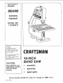
Craftsman 113244513 Owner's manual
- Category
- Power tools
- Type
- Owner's manual
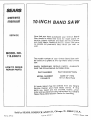
Craftsman 113244513 is a versatile power tool designed for precise and efficient cutting of various materials. With its robust construction and user-friendly features, it offers a range of capabilities to meet your woodworking needs.
Key Features:
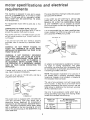
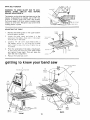
- Powerful Motor: Equipped with a dependable motor, this band saw delivers ample power to handle demanding cutting tasks.
- Adjustable Blade: The adjustable blade tensioning system allows you to fine-tune the blade tension for optimal performance and blade life.
- Precise Cutting: The upper and lower blade guides provide accurate blade tracking, ensuring clean and precise cuts.
Craftsman 113244513 is a versatile power tool designed for precise and efficient cutting of various materials. With its robust construction and user-friendly features, it offers a range of capabilities to meet your woodworking needs.
Key Features:
- Powerful Motor: Equipped with a dependable motor, this band saw delivers ample power to handle demanding cutting tasks.
- Adjustable Blade: The adjustable blade tensioning system allows you to fine-tune the blade tension for optimal performance and blade life.
- Precise Cutting: The upper and lower blade guides provide accurate blade tracking, ensuring clean and precise cuts.


-
 1
1
-
 2
2
-
 3
3
-
 4
4
-
 5
5
-
 6
6
-
 7
7
-
 8
8
-
 9
9
-
 10
10
-
 11
11
-
 12
12
-
 13
13
-
 14
14
-
 15
15
-
 16
16
-
 17
17
-
 18
18
-
 19
19
-
 20
20


Craftsman 113244513 Owner's manual
- Category
- Power tools
- Type
- Owner's manual
Craftsman 113244513 is a versatile power tool designed for precise and efficient cutting of various materials. With its robust construction and user-friendly features, it offers a range of capabilities to meet your woodworking needs.
Key Features:
- Powerful Motor: Equipped with a dependable motor, this band saw delivers ample power to handle demanding cutting tasks.
- Adjustable Blade: The adjustable blade tensioning system allows you to fine-tune the blade tension for optimal performance and blade life.
- Precise Cutting: The upper and lower blade guides provide accurate blade tracking, ensuring clean and precise cuts.
Ask a question and I''ll find the answer in the document
Finding information in a document is now easier with AI
Related papers
-
Craftsman 113.244512 Owner's manual
-
Craftsman 113.235500 Owner's manual
-
-
Sears 113.244530 User manual
-
-
-
-
-
-
Other documents
-
-
Clarke CBS-12WB Owner's manual
-
RIDGID BS14002 User manual
-
COMPANION 172.21399 Owner's manual
-
KNOVA KN SS-162 Owner's manual
-
Hitachi CB13F User manual
-
Porter-Cable PCXB310BS User manual
-
Porter Cable PCXB310BS User manual
-
-
Ryobi BS903 User manual