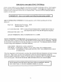
Dunkirk 3E W.65 User manual
- Category
- Water heaters & boilers
- Type
- User manual

[
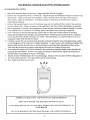
Owner'sManual
MODELNO.
3E W.65
3EW. 75
3EWI';O0
4EW.90
4EWl ;25
4EW1.50
5EWl.20
5EW1.75
5EW2.00
CAUTION
Readaftinstructions
carefully before
starting the installation.
Save this manual
for reference.
Off-Fired
HotWater
Boiler
• Installation
• Operation
• Repair Parts

KENNMORE CAST IRON BOILERS
FULL ONE YEAR WARRANTY ON HOT WATERAND GAS STEAM CAST IRON BOILERS
For one (1) year from the date of installation,when this boiler is installed and maintained in accordance
with our instructions. Sears will repair defects in material or workmanship in the boiler,free of charge.
LIMITED 12 YEAR WARRANTY ON STEAM CAST IRON BOILERS
After one (1} yearand through twelve(12) years from the date of installation,Sears willfurnish a replacement
heat exchanger, ifthe heat exchanger in the boiler isdefective. YOU PAY FOR LABOR.
LIMITED 20 YEAR WARRANTY ON HOT WATER CAST IRON BOILERS
After one (!) year and through twenty (20)yearsfrom the dateof installation,Searswillfurnish a replacement
heat exchanger ifthe heat exchanger in the boiler isdefective. YOU PAY FOR LABOR.
SEARS INSTALLATION WARRANTY
tn addition to any warranty extended to you on the Sears merchandise involved,which warranty becomes
effective the date the merchandise is installed, should the workmanship of any Searsarranged installation
prove faulty within one year, Sears will, upon notice from you, cause such faults to be corrected at
no additional cost to you
FOR WARRANTY SERVICE, SIMPLY CONTACT THE NEAREST SEARS STORE OR SERVICE
CENTER THROUGHOUT THE UNITED STATES. This warranty gives you specific legal rights, and
you may also have other rights which vary from stateto state.
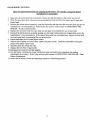
IMPORTANT
The following are the responsibilities of the user and are
not covered by the Warranty
1 Filter clearing or replacement
2 Damage to unit or unsatisfactory operation due to improper
cleaning or use of unit in corroswe atmosphere
3 Damage to unit or unsatisfactory operation due to blown
fuses or inadequate or _nterrupted electrical protective
devices
4 Damage to unit caused by the use of components or other
accessones not compatible with the unit
5. If the unit is removed from the place it was originally
installed, this Warranty becomes void.
6 Damage to the unit caused by accident, abuse, negligence,
misuse, riot, fire, flood, or acts of God
SEARS ROEBUCK AND COMPANY
D/817WA
Hoffman Estates, IL 60179

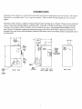
INTRODUCTION
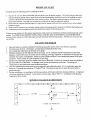
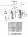
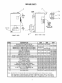
The Empire Water boiler is a natural draft oil fired hot water boiler comprised of cast iron sections. The Empire
Water boiler is available with 3, 4, or 5 cast iron sections. These sections are held together by cast iron push
nipples.
The Empire Water boiler is capable of firing #2 fuel oil from 0.65 gph up to 2.00 gph. Boilers may be purchased
with or without the following options: a Beckett AFG, Carlin EZ, or Rie[lo 40 oil burner, a Taco or Grundfos
circulator with isolation valves, a tankless coil for domestic hot water. All packaged boilers include a swing
door, Honeywell aquastat, temperature and pressure gage, relief valve, drain valve, 2 Delevan oil nozzles for
multiple firing rates (only when purchasing a burner), flue brush, and an extra boiler tap for an expansion tank or
air elimination.
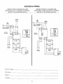
36"
1/4"
RETURN
NIPPLE
&
RIEDUCING
TEE
--*-- 2o I/2"
TIE_ml
PRIESSUR_
GAUGIE
r i
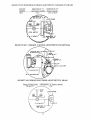
FRONT VIEW
UMIT
j CONTROL
(W_lh=_t
Tanklos=
oll)
LIMIT
CONTROL
(_Bh
Tonkiel=
co==)
,7.l/a"
RIEU.O
T3 3/4"
BIECKETT
OR
CARUN
t I P-'f
I I I--.-.I
BURN
DRAIN
VALVE
(Furnished)
A
'_ WATIER
OUTLET
RIGHT SIDE VIEW
WITH SWING DOOR
OPTIONAL
TANKLESS
J COIL
WATIER
HEATER
WITH 1/2" NPT
CONNECTIONS
RIEUIEF
VALVIE "_
OUTLET
BACK VIEW

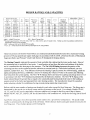
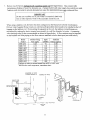
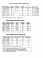
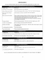
BOILER RATINGS AND CAPACITIES
BOIIiR MOI)EI.NO
Wlill WIIIIOU I
IANK[ISS IANKIESS
('Oil ('OIl
niw (_5I ¸ 3[!W65Z -
31,W 751 3EW 75Z
31!WI OttI ¸ 3EWI IRIZ
4[iw 90T 4EW 99Z
41!WI 251 4EWI 25Z
41LWl 501 4EWl 50Z
5EWI 20'I 5EWI 20Z
5EWI.75 I 5EWI 75Z
5[-W2 00"[ SEW200Z
NO INPUI **llliA'[ ING
Sli(' +M[_II ( APA('IIY
*MBH
3 91 80
3 105 92
3 140 II9
4 126 II[
4 175 150
4 210 178
5 168 147
5 245 209
5 280 236
NET DIMENSIONS (inches)
I=B:R HRING A t: tJ I MINIMUM
RA'I IN(i RA'II_ _+ CHIMNEY
*MBH +GPH SIZE / HEIGHT A B C
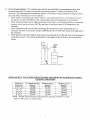
70 0.65 863 8" X 8" X 15' 14+1/2 6 8
80 075 852 8" X 8"X 15' 14-1/2 6 8
103 100 83 4 8" X 8" X 15' 14-1/2 6 8
97 090 860 8" X 8" X 15' 17-3/4 6 9-5/8
130 I +25 839 8" X 8" X 15' 17-314 6 9-5/8
155 150 82.4 8" X 8" X ]5' 17-3/4 6 9-5/8
128 1+20 865 8" X 8" X 15' 21 6 1I-I/2
182 1.75 836 8" X 8" X 15' 21 6 11-1/2
205 2 00 820 8" X 8" X 20' 21 6 [ I-I/2
*MBH 1,000 BTU per hour BTU British Thermal Unit
+'*Heating Capacity based on 13% CO2 with a -0.02" w.c draft over fire, and a #1 smoke or less. Testing was done in accordance with the D.O.E.
(Department of Energy) test procedure.
_GPB Gallons per hour oil at 140,000 BTU per gallon
+ _A F U E. = Annual Fuel Utilization Efficiency based upon DOE test procedure.
These low pressure oil fired hot water boilers are constructed and hydrostatically tested for a maximum working
pressure of 50 psig (pounds per square inch gage) in accordance with A.S.M.E. (American Society of Mechanical
Engineers) Boiler and Pressure Vessel Code Section IV Standards for heating boilers.
The Heating Capacity indicates the amount of heat available after subtracting the losses up the stack. Most of
this remaining heat is available to heat water. A small portion is heat from the jacket and surfaces of the boiler,
and it is assumed that this heat stays in the structure. The Net I=B=R Rating represents the portion of the
remaining heat that can be applied to heat the radiation or terminal units (i.e. finned tube baseboard, cast iron
radiators, radiant floor, etc.). The difference between the Heating Capacity and the Net I=B=R Rating, called the
piping and pickup allowance, establishes a reserve for heating the volume of water in the system and offsetting
heat losses from the system piping. The Net I=B-R Ratings shown are based on a piping and pickup factor of 1.15
in accordance with the I-B-R Standard as published by the Hydronics Institute. The Net I=B=R Rating of the
boiler selected should be greater than or equal to the calculated peak heating load (heat loss) for the building or
area(s) served by the boiler and associated hot water heating systems. The manufacturer should be consulted
before selecting a boiler for installations having unusual piping and pickup requirements.
Boilers with the same number of sections are identical to each other except for their firing rate. The firing rate is
deternuned by the nozzle size in the oil burner and the oil pressure at the nozzle. For example: Models 3E.65Z,
3E.75Z, and 3El .00Z are the same boiler, without a tankless coil, except for the firing rate of the oil burner.
Models 4E.90T, 4El .25T, and 4El.50T are the same boiler, with a tankless coil, except for the firing rate of the oil
burner.
Each boiler rating plate shows three possible model nutnbcrs for a given boiler configuration. The actual model
tmnaber is determined by the firing rate of the oil burner. Boilers that are factory packaged include two nozzles for
two firing rates. These boilers operate on #2 Heating Oil.

RULES FOR SAFE INSTALLATION AND OPEIL_TION
1. Read the Owner's Manual for Safe Operation carefidly. Failure to tbllow tile rules tbr sale operation and
the instructions can cause a malflmction of the boiler and resuh in death, serious bodily injury, and/or
property damage.
2. Check your local codes and utility requirements before installation. The installation nmst be in accordance
with their directives, or follow NFPA 31 - Installation of Oil Burning Eqnipment, latest revision.
3. Before serTicing, allow boiler to cool. Always shut offany electricity and oil to boiler when working on it.
4. Inspect oil line and connections for leaks.
5. Be certain oil burner nozzle is the size required. Overfiring will result in early failure of the boiler sections.
This will cause dangerous operation.
6. Never vent this boiler into an enclosed space. Always vent to the outside. Never vent to another room or
inside a building.
7. Be sure there is adequate air supply for complete combustion.
8. Follow a regular service and maintenance schedule for efficient and safe operation.
9. Keep boiler area clean and free of combustible material, gasoline and other flammable vapors and liquids.
10. Oil burners are not do-it yourself items. This boiler must be installed and serviced by qualified
professionals using combustion test instruments.
11. Be aware when piping the relief valve that if the system pressure exceeds the safe limit of 30 pounds per
square inch, the relief valve will automatically lift open. Lifting of the relief valve can discharge large
quantities of steam and hot water, which may damage the surroundings. Before installing the relief valve
read the manufacturer's instructions and maintenance section of the manual on relief valves.
12. Installation and sizing of the expansion tank must consider the heating systems total water volume,
temperature, boiler initial fill pressure, and system arrangement. An improperly installed and sized
expansion tank may result in frequent lifting of the relief valve or other heating system problems. For
proper installation, sizing, and maintenance of the expansion tank follow the guidelines established by
Dunkirk Radiator Corporation and the expansion tank manufacturer.
13. Expansion tank performance and life expectancy can be hindered by overfilling the boiler. Dunkirk
Radiator Corporation recommends an initial fill pressure of 10-12 psig. For higher fill pressures the
expansion tank's air charge will need to be increased to match the fill pressure. Consult the manufacturer's
guidelines for sizing and selection.
14. Purging the heating system of air and gases when first putting the boiler's into service is critical for proper
circulation and quiet performance. Once the air and gases are purged, for boiler installations using float
type vents, the air vents should be closed for normal operation. If air is heard or noticed by a loss of heat,
purge the system and open the vents for a short period of time.
WARNING
This boiler has been designed for residential installations. If used for commercial applications,
all jurisdictional requirements must be met. This may require wiring and/or piping
modifications. The manufacturer is not responsible for any changes to the original design.
I DO NOT USE GASOLINE CRANKCASE DRAININGS OR ANY OIL CONTAINING GASOLINE. [

BEFORE YOU START
Complete all of the following prior to installing the boiler.
A. Check to be sure you have selected the right size boiler with the proper capacity. The I=B=R rating of the boiler
selected should be greater than or equal to the calculated peak heating load (heat loss) for the building or area(s)
served by the boiler and associated hot water heating systems. See boiler rating and capacity table previously
listed in this manual. Any heat loss calculations used should be based on approved methods.
B. Boiler rdust be supplied with the proper oil supply and oil piping, sufficient fresh combustion air, and a suitable
electrical supply.
C. Boiler must be connected to a suitable venting system and a piping system adequate to distribute the heating load.
D. A thermostat must be properly located and installed for control of the heating system.
If there are any doubts as to the various requirements, check with local authorities and obtain professional help where
needed. The OPERATING INSTRUCTIONS, FINAL CHECKS AND ADJUSTMENTS, and MAINTENANCE
sections in this manual are vital to the proper and safe operation of the heating system. Take the time to be sure they
are all done.
LOCATING THE BOILER
1. Place the boiler in a location centralized with the piping system and as close to the chimney as possible.
2. The boiler must be level. If necessary use metal shims beneath the boiler's feet.
3. Use a raised base if the floor can become wet or damp.
4. Maintain clearances for fire safety as well as servicing. An 18" clearance must be maintained at a side where
passage is required for access to another side for cleaning, servicing, inspection, or replacement of any parts that
normally may require such attention. Boilers must be installed at least 6" from combustible material on all sides
and above. Allow at least 24" front clearance for servicing.
5. Fresh air for combustion must be available at the front of the boiler. Fresh air for ventilation must be available to
the front AND rear of the boiler. Air passages must be free of obstructions at all times. Ventilating and
combustion air must enter boiler room without restrictions.
6. The floor supporting the boiler must be non-combustible and sufficiently stable. If it is combustible, place the
boiler on 2" concrete patio blocks or 2" Cladlite TM Pad. The blocks or pad must be under the entire boiler to
protect the floor.
7. Be sure installation is in accordance with the requirements of the local authorities having jurisdiction. Compliance
with these regulations is required. In the absence of local codes, follow NFPA 31 - Installation of Oil Burning
Equipment, latest revision.
MINIMUM CLEARANCE DIMENSIONS
f_
I
co'
O
6" MIN.
41
24" MIN.
+
_[ BOILER L 6" MIN.
v _FRONT t "q
t
6" MIN. / 18" WITH COIL
A_
,'x.
_C
C
4

ALWAYS KEEP TILE NL_NUAL FUEL SUPPLY VALVE SHUT OFF, IF THE
BUI_NER IS SHUT DOWN FOR AN EXTENDED PERIOD OF TIa_clE.
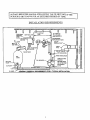
I_NSTALLATION REQUIRELMENTS
1
SHUT OFF
VALVE
OIL RLTER
2**
FI LL PiPE
MIN 2"
VENT PIPE
OIL
TANK
LINESTO OTHER
APPLIANCES
TO OUTSIDE
ELECTRIC
LINE
AUTOMATIC
FILL VALVE
NOSHUTOFF
EXPANSION TANK
DRAFT
REGULATO_
VENT
PiPE
RELIEF VAI
,TION
,FROM RADIATION
CIRCULATIHG
RETURN LINE
OR AbTER TI-I]£
EXPANSION
TANK

FRESH AIR FOR COMBUSTION
WARNING I
Be sure to provide enough fresh air for combustion. Enough air ensures proper
combustion and assures that no hazard will develop due to the lack of oxygen.
I NOTE [
If you use a fireplace or a kitchen or a bathroom exhaust fan, you should install an
outside air intake. These devices will rob the boiler and water heater of combustion air.
You must provide enough flesh air to assure proper combustion. The fire in the boiler uses oxygen. It must have a
continuous supply. The air in the house contains only enough oxygen to supply the burner for a short time. Outside
air must enter the house to replace the air used by the burner. Study the following examples 1 and 2 to determine your
fresh air requirements.
EXAMPLE 1: Boiler Located in Unconfined Space
If your boiler is in an open area (unpartitioned basement) in a conventional house, the air that leaks through the cracks
around the doors and windows will usually be adequate to provide air for combustion. The doors should not fit tightly.
Do not caulk the cracks around the windows.
An unconfined space is defined as a space whose volume is not less than 50 cubic feet per 1,000 Btu per hour of the
total input rating of all appliances installed in that space.
EXAMPLE 2: Boiler Located in Confined Space
A. All Air from Inside the Building: The confined space shall be provided with two permanent openings
communicating directly with an additional room(s) of sufficient volume so that the combined volume of all spaces
meets the criteria for an unconfined space. The total input of all combustion equipment installed in the combined
space shall be considered in making this determination. Each opening shall have a minimum free area of one
square inch per 1,000 Btu per hour of the total input rating of all combustion equipment in the confined space, but
not less than 100 square inches. One opening shall be within 12 inches of the top and one within 12 inches of the
bottom of the enclosure.
Example: Your boiler is rated at 100,000 Btu per hour. The water heater is rated at 30,000 Btu per hour. The
total is I30,000 Btu per hour. You need two grilles, each with 130 square inches of FREE opening. Metal grilles
have about 60% FREE opening. To find the louvered area needed, multiply the free opening required by 1.7 (130
x 1.7 = 221.0 sq. in. louvered area). In this example, two grilles each having an 8" x 30" (24-0 sq. in.) louvered
area would he used.
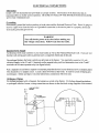
AIR OPENINGS FOR BOILER LOCATED IN CONFINED SPACE (CLOSET OR UTILITY ROOM)
VENTILATING I
GRILLE 1
I
I
I
I'
COMBUSTION
AIR GRILLE
6

B. All Air from Outdoors: The confined space shall be provided with two permanent openings, one
commencing within 12 inches of the top and commencing within 12 inches of the bottom of the
enclosure. The openings shall communicate directly, or by ducts, with the outdoors or spaces (crawl or
attic) that freely communicate with the outdoors.
1. When directly communicating with the outdoors, each opening shall have a minimum free area of
one square inch per 4,000 Btu per hour of total input rating of all equipment in the enclosure.
2. When communicating with the outdoors through vertical ducts, each opening shall have a minimum
flee, area of one square inch per 4,000 Btu per hour of total input rating of all equipment in the
enclosure.
3. When communicating with the outdoors through horizontal ducts, each opening shall have a
minimum free area of one square inch per 2,000 Btu per hour of total input rating of all equipment in
the enclosure.
4. When ducts are used, they shall be of the same cross-sectional area as the free area of the openings to
which they connect. The minimum dimension of rectangular air ducts shall be not less than three
inches.
FRESH
AIR
FRESH AIRDUCTCAPACITIESFORDUCTSSUPPLYINGFRESH _RTOBOILERINTIGHTLY
CONSTRUCTED HOUSES
Fresh Air
Duct Size
3J/2 '" x 12"
8" x 8"
8" x 12"
8"x 16"
¼" Mesh Screen
(Btuh)*
144,000
256,000
384,000
512,000
Wood Louvers
(Btuh)*
36,000
64,000
96,000
128,000
Metal Louvers
(Btuh)*
108,000
192,000
288,000
384,000
*Btuh = British Thermal Units per hour based on opening covered by ¼" mesh
screen, wood louvers, or metal louvers.

SYSTEM PIPING
I. When the installation of the boiler is for a new heating system, first instal! all of the radiation units
(panels, radiators, baseboard, or tubing) and the supply and return mains. After all heating system piping
and components have been installed, make final connection of the system piping to the boiler. It is
recommended to mount the circulating pump on the supply side piping, such that it pumps away from the
expansion tank. Refer to the figures on the next pages.
2. A hot water boiler installed above radiation level must be equipped with a low water cut off device. A
periodic inspection is necessary, as is flushing of float type devices, per low water cut off manufacturers
specific instructions.
.
The packaged boiler unit is set up with 1-1/4" NPT supply and return piping from the front of the boiler.
The boiler supply and return piping can be moved to the rear of the boiler. The boiler should not be piped
return line to the front, supply line to the rear, or vice versa, as this will cause the boiler water to short
circuit the heat exchanger. Piping connections may require additional fittings and parts.
,
The relief valve is meant to be installed in the back side of the rear section using the 3/4" nipple and street
ell provided in the parts bag. Connect a discharge pipe of the same pipe size (3/4") to carry any water away
to a drain. Do not connect directly to a drain, but leave an air gap. No shutoffof any description shall be
placed between the safety relief valve and the boiler, or on discharge pipes between such safety valves and
the atmosphere. Installation on the safety relief valve shall conform to the ANSI/ASME Boiler and Pressure
Vessel Code, Section IV. The manufacturer is not responsible for any water damage.
5. When connecting the cold water supply to the pressure reducing valve, make sure that a clean water supply
is available. When the water supply is from a well or pump, a sand strainer should be installed at the pump.
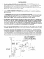
. The minimum boiler supply water temperature setting on the aquastat is 140°F. If the boiler is used in a
heating system where supply water temperatures below 140°F are desired, a suitable method, such as, the
use of bypass piping shown in the figure below, a 3 way or 4 way mixing valve, or some other means
needs to be used to ensure return water temperatures to the boiler are no less than 120°F. When the boiler is
operated with return water temperatures less than 120°F, condensation may form in the boiler and venting.
This condensation is corrosive and can eventually cause severe damage to the boiler and venting system.
RETURN FROM SYSTEM
I
DRAINVALVE
FOR POWER
PURGING
SHUTOFF VALVE
BOILERSERVICE
MAIN SHUTOFF
VALVE
AUTOMATIC
FILL VALVE
i/_ADJUST THE TWOTHROTTLINGVALVESTO
MAINTAINAT LEAST12O'F IN THE
BOILERRETURN.THE THROTTLINGVALVES
ARE USED FORBYPASSPIPING,IF REQUIRED.
THROTTLINGVALVE l
CIRCULATOR
PUMP l
OffUNG VALVE
SUPPLY TO
SYSTEM
ISOLATIONVALVES
_FILL LINE WITHSHUTOFFVALVE
FILLTROLWITH
AIR PURGER
BOILER
DRAIN
VALVE 8

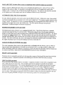
SYSTEM PIPING ARRANGEMENT
ZONING WITH ZONE VALVES
> CIRCULATOR ON SUPPLY PIPING PUMPS
AWAY FROM EXPANSION TANK
>
PIPING ARRANGED FOR "POWER P[VRGING"
AIR OUT OF SYSTEM PIPING, REFER TO THIS
MANUAL'S SECTION ON "FILLING THE
SYSTEM _,VITH WATER" OPTION #1
BALANCINGVALVE
ZONE VALVE
RETURNFROMSYSTEM
IT
I RAIN VALVE
FOR POWER
PURGING
MAINSHUTOFF
VALVE
SUPPLYTO
SYSTEM
CIRCULATOR
PUMP
SHUTOFFVALVE
BOILERSERVICE
FILL VALVE
FILLTROLWITH
AIR PURGER
_._"-_ SUPPLYTO
SYSTEM
ISOLATIONVALVES
LiNE WITH SHUTOFFVALVE
BOILER
DRAIN
VALVE

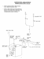
SYSTEM PIPING ARRANGEMENT
ZONING WITH CIRCULATORS
CIRCULATOR ON SUPPLY PIPING PUMPS
AWAY FROM EXPANSION TANK
PIPING ARRANGED FOR "POWER PURGING"
AIR OUT OF SYSTEM PIPING, REFER TO THIS
MANI_AL'S SECTION ON "FILLING THE
SYSTEM WITH WATER" OPTION #1
RETURNFROMSYSTEM
[ _ DRAINVALVE
FOR POWER
PURGING
MAIN SHUTOFF
VALVE
AUTOMATIC
FiLLVALVE
SHUTOFF VALVE
BOILERSERVICE
_QUASTA
BOILER
DRAIN
VALVE
R
I0
7
FILLTROLWITH
AIR PURGER
BALANCINGVALVE
FLOWCHECK VALVE
_ ZONE CIRCULATOR
_I ISOLATIONVALVE
SUPPLY TO
SYSTEM
SUPPLYTO
SYSTEM
FILLLINEWITH SHUTOFF
VALVE

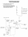
SYSTEM PIPING ARRANGEMENT
ALTERNATE NEAR BOILER PIPING
DIAPHRAGM EXPANSION TANK MOUNTED OFF THE BOILER
> CIRCULATOR ON SUPPLY PIPING PUMPS AWAY FROM EXPANSION TANK
PER THIS MANUAL, USE OPTION #2 IN "FILLING THE SYSTEM WITH \VATER"
THIS PIPING ARRANGE_IENT CAN BE USED WITH ZONE VALVES OR ZONE CIRCULATORS
RETURN FROM SYSTEM
ISOLATION
VALVES
SHUTOFF VALVE
BOILERSERVICE
SHUTOFF VALVE
---BOILERSERVICE
CIRCULATOR
PUMP
©
SUPPLY TO
SYSTEM
AUTOMATIC
FILLVALVE
FILLLINEWITH
SHUTOFF VALVE
/
AOUASTAT
FILLTROLWITH
AIRPURGER
BOILER
DRAIN
VALVE
LOCATE CIRCULATORPUMP HERE WHEN SYSTEM
PIPINGUSES ZONE VALVES.IFSYSTEM PIPING
USES ZONE CIRCULATORS,USE THISCIRCULATOR
AS A ZONE CIRCULATOR
II

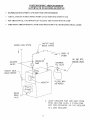
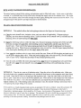
7. Boilers may be factory packaged with a tanMess heater coil see figure below. This coil provides
instantaneous heating of water for domestic use - if proper burner and water supply line controls are used.
Tankless coils are meant to provide domestic hot water for intermittent draws, no_Jcontinuous flow.
IMPORTANT
Do not use a tankless coil if your water is excessively hard with
lime or other deposits which will accumulate inside the coil.
When using a tankless coil, the boiler has been configured so the Honeywell L8124C Combination
Hi/Low Limit Aquastat Relay mounts on a thermowell (provided) which needs to be installed in the 3/4"
tapping on the tankless coil. By mounting the aquastat on the coil, the tankless coil performance is
maximized by making the burner respond more quickly to a call for domestic hot water. A tempering
valve (mixing valve) is also recommended as shown in figure below. A flow restrictor may be required
on the tankless coil inlet piping so that flow rates are matched to boiler heat input (see table below).
Boiler
Model
3EW.65T
3EW.75T
3EWI.00T
4EW.90T
4EW1.25T
4EW1.50T
5EW1.20T
5EW1.75T
5EW2.00T
Burner Firing
Rate (gph)
0.65
0.75
1.00
0.90
1.25
1.50
1.20
1.75
2.00
Input
(MBH)
91
105
140
126
175
210
168
245
28O
Tankless
Rating (gpm):_
2.90
3.00
3.25
3.15
3.50
3.75
3.45
4.00
4.25
:_ Gallons of water per minute heated from 40°F to 140°F with
200°F boiler water temperature, intermittent draw
UNTEM,_I[R[O HOT WAT[R
TANKLESS COIL
OUT
CENTER LINE t
OF COLO TAp
-
L__-
_'Np
12

8. Antifreeze addedto boilers must be non-toxic, and must be of a type specifically intended for use in closed
b_ydronic heating systems. Under no circumstances should automotive antifreeze be used. Antifreeze used
in any boiler may reduce capacity by 10% or more and increase fuel consumption. Tankless coil
performance will fall as concentration of antifreeze is increased. Refer to boiler and piping water volumes
tables in this manual.
BOILER WATER VOLUMES
PIPING WATER VOLUMES
Number of
Boiler Sections
3
4
5
Total Volume
(Gallons)
9.6
11.6
I 13.7
COPPER PIPE STEEL PIPE
PIPE SIZE
FACTOR FACTOR
Y2" 82.5 63.5
¾" 40.0 36.0
1" 23.3 22.2
1-1/4" 15.3 12.8
1-1/2" 10.8 9.5
2" 6.2 5.8
Divide total length of piping in feet by appropriate
factor in table to determine volume in gallons.
13

I or oil-fired boilers for connections to vents or chimneys, vent installations shall be in
accordance with applicable provisions of INSTALLATION OF OIL BURNING
EQUIPMENT, NFPA-31 - latest revision, and applicable provisions of local building codes.
CHIMNEY AND CHIMNEY CONNECTIONS
This is a very important part of your heating system. No boiler, however efficient its design, can perform
satisfactorily if the chimney that serves it is inadequate. Check your chimney to make certain that it is the
right size, properly constructed and in sound condition.
It is cheaper to rebuild a poor chimney than to pay excessive fuel bills. If yours is an old chimney, a new
steel liner or a new prefabricated chimney may be the best solution. The following chart shows
recommended minimum chimney sizes based on Table 3 and Figure 6 of the I=B=R Testing and Rating
Standard for Heating Boilers, Sixth Edition, June 1989.
RECOMMENDED MINIMUM CHIMNEY SIZES
NOMINAL ROUND LINER - SQUARE LINER -
FIRING RATE CHIMNEY
CHIMNEY INSIDE INSIDE
(gph) HEIGHT (ft) AREA DIAMETER I DIMENSIONS
0.60 - 1.30 15 8" x 8" 6" I 6-3/4" x 6-3/4"
1.31 - 1.80 15 8" x 8" 7" 6-3/4" x 6-3/4"
1.81 - 2.00 20 8" x 8" 8" 6-3/4" x 6-3/4"
:or elevations above 2,000 feet above sea level, add 3 feet to the chimney heights. See Figure below.
For additional chimney design and sizing information, consult the ASHRAE 1996 HVAC Systems and
Applications Handbook, Chapter 30, Gas Vent and Fireplace Systems; or the National Standard for
Chimneys, Fireplaces, Vents and Solid Fuel Burning Appliances, ANSI/NFPA 211.
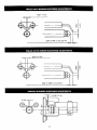
CHIMNEY CONNECTOR AND DRAFT REGULATOR
Venting the boiler requires a 6" diameter chimney connector pipe and using the draft regulator packed with
the boiler. Properly installed, the regulator will control the draft automatically. It is better to install it in a
horizontal section of pipe, but it may be installed in an angled or vertical section of pipe. Make certain that
the "top" of the regulator is at the top - and that the short pipe section which holds the vane is horizontal.
Even though locating the draft regulator close to the chimney reduces noise, install the draft regulator as
close as practicable to the boiler.
To install the chimney connector, start at the boiler with a vertical pipe and then elbow - then install the draft
regulator making it horizontal. When the regulator is in place, start at the chimney and work back to the
regulator. Join the two sections with a drawband. The horizontal pipe must slope up toward the chimney at
least 1/4 inch per linear foot of venting. The chimney connector must not leak and must be firmly supported.
Join each of the sections with at least two sheet-metal screws. Support every second section with a stovepipe
wire.
Maintain a minimum vent pipe clearance of 18" from the surface of the vent to wood and other
combustible materials.
14

TYPICAL CHIMNEY CONNECTION
MUST BE AT LEAST 4
INCHES THICK-
AND BE TIGHT.
MUST SLOPE UP
AT LEAST 1/4 INCH
PER FOOT OF
HORIZONTAL RUN
DRAWBAND
LAST PIECE
INSTALLED
TIGHT, SMOOTH,
CORRECTLY SIZED.
I
I
!
• SEALED IN
THIMBLE
.TIGHT
CLEAN-OUT
DOOR
MUST BE REQUIRED MIN-
IMUM HEIGHT• MUST RE
AT LEAST 3 FT. HIGHER
THAN HIGHEST PART QF
PASSAGE THROUGH
ROOF. MUST BE AT
LEAST 2 FT. HIGHER
THAN ANY NEIGHBORING
OBJECT. MUST HAVE AN
UNOBSTRUCTED TOP
OPENING.
DRAFT REGULAT(
VANE
CRIMPEDENO
BALANCED WEIGHT
ALTERNATE POSITIONS
. TOP
15

ELECTRICAL CONNECTIONS
Thermostat
Install a 24-volt thermostat (not provided) in a proper location. The location of the thermostat has an
important effect on boiler system operation. BE SURE TO FOLLOW THE INSTRUCTIONS INCLUDED
WITH THE THERMOSTAT.
Grounding
Permanently ground the boiler according to local codes and the National Electrical Code. Run a 14 gauge or
heavier copper wire from the boiler to a grounded connection in the service panel or a properly driven and
electrically grounded ground rod.
I
WARNING
Turn off electric power at fuse box before making any
line voltage connections. Follow local electrical codes.
I
Electric Power Supply
All electrical work must conform to your local codes as well as the National Electrical Code. If you are not
familiar with wiring and codes in general, have a competent electrician do this job.
On packaged boilers, the boiler controls are all wired at the factory. You need only connect a 115 volt
electrical supply to the L1 and L2 terminals on the aquastat relay and two thermostat wires to the T and T
terminals on the same aquastat relay (see figure below).
Run a separate circuit from a separate overcurrent protection device in your electrical service entrance panel.
This should be a 15 ampere circuit. Locate a shut-off switch at the boiler. It must be turned offduring any
maintenance. Solder and tape or securely fasten these connections with wire nuts.
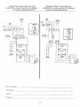
Oil Burner Wiring
For boilers packaged with oil burners, the burners are wired at the factory. For boilers shipped knockdown
or packaged without a burner, wiring connections are shown in the electrical wiring diagrams of this manua!.
115V 60 CYCLE
N H SUPPLY
It
,_24 VOLT
THERMOSTAT
II
AQUASTAT
RELAY
16

SE_/ARS
KENNMORE CAST IRON BOILERS
FULL ONE YEAR WARRANTY ON HOTWATER AND GAS STEAM CAST IRON BOILERS
For one (1}year from the date of installation,when this boiler is installed and maintained in accordance
with our instructions Searswill repair defects in material or workmanship in the boiler,free of charge.
LIMITED 12 YEAR WARRANTY ON STEAM CAST IRON BOILERS
%_ After one (1)yearand through twelve (12)years from the date o| installation,Searswill furnish a replacement
heat exchanger, ifthe heat exchanger in the boiler isdefective.YOU PAYFOR LABOR.
__ LIMITED 20 YEAR WARRANTY ON HOT WATER CAST IRON BOILERS
After one (! }yearand through twenty (20) years from thedate of installation,Searswill furnisha replacement
heat exchanger if the heat exchanger in the boiler is defective.YOU PAY FOR LABOR.
SEARS INSTALLATION WARRANTY
Inaddition to any warranty extended to you on the Sears merchandise involved,which warranty becomes
effective the date the merchandise is installed,should the workmanship of any Sears arranged installation
prove faulty within one year, Sears will, upon notice from you, cause such faults to be corrected at
no additional cost toyou
FOR WARRANTY SERVICE, SIMPLY CONTACT THE NEAREST SEARS STORE OR SERVICE
CENTER THROUGHOUT THE UNITED STATES. This warranty gives you specific legal rights,and
you may also haveother rightswhich vary from stateto state
IMPORTANT
The following are the responsibilities of the user and are
not covered by the Warranty
1 Filter clearing or replacement
2 Damage to unit or unsatisfactory operation due to improper
cleaning or use of unit in corrosive atmosphere
3 Damage to unit or unsatisfactory operation due to blown
fuses or _nadequate or interrupted electrical protective
devices
4 Damage to unit caused by the use of components or other
accessories not compatible with the unit
5 If the unit _s removed from the place it was originally
installed, this Warranty becomes void
6 Damage tothe unit caused by accident, abuse, negligence,
m_suse, riot, fire, flood, or acts of God
SEARS ROEBUCK AND COMPANY
D/817WA
Hoffman Estates, IL 60179

MAIN AIR VENT: for down flow systems or diaphragm type expansion tanks (not provided)
Before a system is filled with water, there is air in the pipes and radiation units• Some of the air will be
trapped as the system is filled. It is possible to eliminate most of this air through the air vents on the
radiation units• A main air vent will speed and simplify this process. The main air vent should be installed
on the highest point in the supply main when all radiation is below the top of the boiler.
AUTOMATIC FILL VALVE (not provided)
For safe, efficient operation, a hot water system must be filled with water. Adding new water, when needed
can be done manually (by use of a hand valve in the water supply line). This requires regular attention to the
system's needs. An automatic fill valve or pressure reducing valve accomplishes this without attention. It is
installed in the supply line on hot water boilers only. The valve operates through water pressure
differentials. It does not require an electrical connection.
BURNER SOLENOID VALVE (provided)
The Beckett and Carlin oil burner's use a standard solenoid valve. Upon burner shut down, a standard
solenoid valve stops the flow of oil to the nozzle. Without the solenoid valve, the oil pump continues to
pump oil to the burner nozzle until the burner motor winds down below the pumps cut-offspeed. The Riello
oil burner has a dela£ solenoid valve. The delay solenoid valve provides the same shut down action as the
standard solenoid valve, plus on burner start up the delay solenoid valve remains closed for an additional 15
seconds. This allows the burner fan motor to pre-purge the combustion chamber and the oil pump to bring
the supply oil pressure up to its set point helping to provide a clean light off.
AQUASTAT RELAY CONTROL (provided)
The water temperature limit control in the aquastat relay is adjustable and may be set: as low as 140°F so
long as return water temperatures to the boiler are no less than 120°F, or as high as 240°F so long as the
boiler and heating system have adequate circulation to remove the heat from the boiler otherwise steam may
be created in the boiler. Refer back to SYSTEM PIPING section for more information.
DRAIN VALVE (provided)
The drain valve is a manually operated valve that provides a means of draining all the water from the boiler
and heating system. It should be installed in the reducing tee where the return line enters the boiler.
CIRCULATOR (provided)
Every forced hot water system requires a circulator. A separate circulator or zone valve is required for each
zone, if there are two or more zones. The circulator must have the capacity to provide the circulation
required by the heating system. The circulator should be connected to the supply main and must be wired
into the boiler's electrical system. See the SYSTEM PIPING section for piping configurations with the
circulator located on the supply main piping using zone circulators or zone valves. When the piping is
arranged with zone circulators and no bypass piping, the circulator provided with the boiler may be used as a
zone circulator. Both piping arrangements allow the circulator to pump away from the expansion tank and
show how the piping should be arranged to allow the heating system to be easily purged of air.
18
Page is loading ...
Page is loading ...
Page is loading ...
Page is loading ...
Page is loading ...
Page is loading ...
Page is loading ...
Page is loading ...
Page is loading ...
Page is loading ...
Page is loading ...
Page is loading ...
Page is loading ...
Page is loading ...
Page is loading ...
Page is loading ...
Page is loading ...
Page is loading ...
Page is loading ...
Page is loading ...
Page is loading ...
-
 1
1
-
 2
2
-
 3
3
-
 4
4
-
 5
5
-
 6
6
-
 7
7
-
 8
8
-
 9
9
-
 10
10
-
 11
11
-
 12
12
-
 13
13
-
 14
14
-
 15
15
-
 16
16
-
 17
17
-
 18
18
-
 19
19
-
 20
20
-
 21
21
-
 22
22
-
 23
23
-
 24
24
-
 25
25
-
 26
26
-
 27
27
-
 28
28
-
 29
29
-
 30
30
-
 31
31
-
 32
32
-
 33
33
-
 34
34
-
 35
35
-
 36
36
-
 37
37
-
 38
38
-
 39
39
-
 40
40
-
 41
41


Dunkirk 3E W.65 User manual
- Category
- Water heaters & boilers
- Type
- User manual
Ask a question and I''ll find the answer in the document
Finding information in a document is now easier with AI
Related papers
-
Dunkirk Empire EWC Installation & Operation Manual
-
-
-
-
-
-
-
 Excelsior Excelsior EXB Series Installation, Operation And Maintanance
-
-

Other documents
-
Beckett Water Gardening Pond Filter RFPCOMBO User manual
-
Lennox COWB3 Installation guide
-
Bryant BW4 Owner's manual
-
 UTICA BOILERS SW3 Installation, Operation & Maintenance Manual
-
Smith 8 Series Installation And Operating Instructions Manual
-
Crown Boiler Nassau Series (all Models) User manual
-
 UTICA BOILERS JE Installation & Operation Manual
-
Kenmore 229965520 Owner's manual
-
 Boyertown Furnace Solaia SL5125 User manual
-
 UTICA BOILERS BC Series II Installation & Operation Manual


