
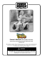
®
Owner’s Manual with Assembly Instructions
Please read this manual and save it with your original sales receipt.
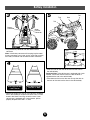
For Model 76950
Tools needed for assembly: Phillips and Slotted Screwdrivers, Hammer, Pliers and Safety Scissors.
Use only with a Power Wheels
®
6 Volt (4.0 Amp/hr.) Battery, Power Wheels
®
25 Amp Fuse
and Power Wheels
®
6 Volt Charger (all included).
CAUTION
ELECTRIC TOY: Not recommended for children under 1 year of age.
As with all electric products, precautions should be observed during
handling and use to prevent electric shock.
Product features may vary from the picture above.

CAUTION
Use the charger indoors only.
2
Table of Contents
Important Information
A Important Information . . . . . . . . . . . . . . . . . . . . . . . . . . . . . . . . . . . . . . . . . . . . . . . . . . . . . . . . . . . . . . . . . . . . .2
B Warnings . . . . . . . . . . . . . . . . . . . . . . . . . . . . . . . . . . . . . . . . . . . . . . . . . . . . . . . . . . . . . . . . . . . . . . . . . . . . . .3
C Parts . . . . . . . . . . . . . . . . . . . . . . . . . . . . . . . . . . . . . . . . . . . . . . . . . . . . . . . . . . . . . . . . . . . . . . . . . . . . . . . . .4
D Parts Diagram . . . . . . . . . . . . . . . . . . . . . . . . . . . . . . . . . . . . . . . . . . . . . . . . . . . . . . . . . . . . . . . . . . . . . . . . . . .6
E Battery Charging . . . . . . . . . . . . . . . . . . . . . . . . . . . . . . . . . . . . . . . . . . . . . . . . . . . . . . . . . . . . . . . . . . . . . . . . .7
F Assembly . . . . . . . . . . . . . . . . . . . . . . . . . . . . . . . . . . . . . . . . . . . . . . . . . . . . . . . . . . . . . . . . . . . . . . . . . . . . . .9
G Label Decoration . . . . . . . . . . . . . . . . . . . . . . . . . . . . . . . . . . . . . . . . . . . . . . . . . . . . . . . . . . . . . . . . . . . . . . . .15
H Battery Installation . . . . . . . . . . . . . . . . . . . . . . . . . . . . . . . . . . . . . . . . . . . . . . . . . . . . . . . . . . . . . . . . . . . . . .16
I Battery Care and Disposal . . . . . . . . . . . . . . . . . . . . . . . . . . . . . . . . . . . . . . . . . . . . . . . . . . . . . . . . . . . . . . . .19
J Rules for Safe Driving . . . . . . . . . . . . . . . . . . . . . . . . . . . . . . . . . . . . . . . . . . . . . . . . . . . . . . . . . . . . . . . . . . . .19
K Attaching and Removing Your Vehicle from the Base . . . . . . . . . . . . . . . . . . . . . . . . . . . . . . . . . . . . . . . . . . . . .21
L How to Operate Your Vehicle . . . . . . . . . . . . . . . . . . . . . . . . . . . . . . . . . . . . . . . . . . . . . . . . . . . . . . . . . . . . . . .23
M Caring for Your Vehicle . . . . . . . . . . . . . . . . . . . . . . . . . . . . . . . . . . . . . . . . . . . . . . . . . . . . . . . . . . . . . . . . . . .24
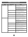
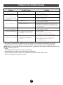
N Problems and Solutions Guide . . . . . . . . . . . . . . . . . . . . . . . . . . . . . . . . . . . . . . . . . . . . . . . . . . . . . . . . . . . . .25
O Statement of Limited Warranty . . . . . . . . . . . . . . . . . . . . . . . . . . . . . . . . . . . . . . . . . . . . . . . . . . . . . . . . . . . . .28
P Authorized Service Centers . . . . . . . . . . . . . . . . . . . . . . . . . . . . . . . . . . . . . . . . . . . . . . . . . . . . . . . . . . . . . . . .28
• The Rock & Roll requires adult assembly. Please set
aside at least 30 minutes for assembly.
• You must charge your battery for 18 - 30 hours BEFORE
YOU USE YOUR VEHICLE FOR THE FIRST TIME.We
recommend that you start charging your battery before
beginning assembly. Please see the Battery Charging
section beginning on page 7 for detailed instructions.
• Read this manual carefully for important safety informa-
tion and operating instructions before using your vehicle.
• Throughout this manual you will find important messages
in the form of WARNINGS, CAUTIONS and NOTES.
WARNING signals something that could hurt your child
or you. CAUTION signals something that can damage
the vehicle. NOTE is used to highlight useful information.
• This vehicle is designed for use on grass, asphalt or
other hard surfaces by children 1 - 3 years of age.
• To prevent damaging the motors and gears, do not tow
anything behind the vehicle or overload it. Do not exceed
the maximum weight capacity of 40 lbs.
A
• If you have any questions about your Power Wheels
®
vehicle, please call our toll-free service lines at
1-800-348-0751 from 8 AM to 6 PM (EST) Monday
through Friday. Trained customer service representatives
are available to take your call in English or French. Habla
Español? Si usted tiene alguna pregunta ó necesita asis-
tencia llame gratis 1-800-348-0755 para los Estados
Unidos. Tenemos representantes que hablan español
para atender su llamada.
• For your convenience, Power Wheels
®
maintains an
Authorized Service Center Network with more than 400
authorized service centers nationwide. Our authorized
service centers will repair or replace parts under war-
ranty at no extra charge, and can perform non-warranty
repairs for a minimal charge. Please see the Authorized
Service Center list beginning on page 28 to find the
authorized service center nearest to you, or call
1-800-348-0751.
• Please complete and return the enclosed Registration
Card today, or call 1-800-348-0751 to register your
vehicle by phone.

WARNING
• Children can be harmed by small parts, sharp edges and sharp points in the vehicle’s
unassembled state, or by electrical items. Care should be taken in unpacking and assembly
of the vehicle. Children should not handle parts, including the battery, or help in assembly of
the vehicle.
• Keep small parts and plastic bags out of children’s reach. Dispose of plastic bags properly.
• Adult supervision is required. Children do not have the judgement necessary to avoid many
accidents. Be sure that children operating this vehicle can do so safely and that they are
supervised at all times.
• Never use near steps, driveways, steep inclines, roadways, alleys, swimming pool areas or
other bodies of water.
• Always wear shoes or sneakers when operating this vehicle.
• Never allow more than one rider.
• The rider should sit on the seat when the vehicle is in operation.
• Hot motor cover. Handle carefully.
• Never alter this vehicle or its electrical system in any way. Alterations could cause a fire
resulting in injury and could also ruin the electrical system.
• Use of the wrong type battery, fuse or charger could cause a fire or explosion, resulting in
serious injury.
• Use of Power Wheels
®
components in products other than Power Wheels
®
vehicles could
cause overheating, fire or explosion.
• The battery must be handled by adults only. The battery is heavy and contains sulfuric acid
(electrolyte). Dropping the battery could result in serious injury.
• Never lift or carry the battery by the wires or connector. This can damage the battery and
possibly cause a fire resulting in injury. Lift and carry the battery by the case only.
• Read the cautions on the back panel of the battery.
• Never allow children to charge the battery. Battery charging must be done by adults only.
A child could be injured by the electricity involved in charging the battery.
• Examine the battery, charger and their connectors for excessive wear or damage each time
you charge the battery. If damage or excessive wear is detected, do not use the vehicle until
you have replaced the worn or damaged part as it could possibly cause a fire resulting in
injury.
Warnings
B
3

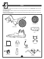
Parts
C
4
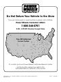
• If you experience a problem with this product or are missing a part, please call us at 1-800-348-0751 rather than return
this product to the store.
• Please identify all parts before assembly and save all packaging material until assembly is complete to ensure that no
parts are discarded.
• Metal parts have been coated with a lubricant to protect them during shipment. Wipe all metal parts with a paper towel
to remove any excess lubricant.
IM
P
O
R
T
A
N
T
A
2
5
A
M
P
F
U
S
E
M
U
S
T
B
E
I
N
S
T
A
L
L
E
D
I
N
T
O
P
O
F
B
A
T
T
E
R
Y
B
E
F
O
R
E
T
O
Y
W
I
L
L
R
E
C
H
A
R
G
E
O
R
O
P
E
R
A
T
E
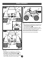
Vehicle Body
U-Clip Set
Front Wheel - 2
6 Volt Battery
Protective Foam Pocket
(Under Seat)
6 Volt Battery
Charger
Handlebar
Headlight
Grille
Seat
1
2
Base

5
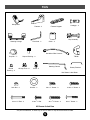
Parts
Footrest - 2
Footrest Support
Microphone
Collar - 2
Steering Linkage
Front Axle - 2
Key Assembly
Knob - 2
T-Slider
Steering Column
Handlebar Wire Harness
Handgrip - 2
Square Bushing - 3
Cap Nut - 7*
Washer - 2
Battery Retainer
25 Amp Fuse - 2*
Round
Bushing - 2
#10 x 1
1
/
4
" Bolt - 2
#10 x
3
/
4
" Screw - 2
#8 x
7
/
8
" Screw - 2
#8 x 1” Screw - 2
#8 x
1
/
2
" Screw - 3
Lock Nut - 2
#10 x
1
/
2
" Bolt
All Shown Actual Size
*For your convenience, an extra cap nut and an extra 25 amp fuse have been included.
Not Shown: Label Sheet

1
2
2
3
4
5
8
8
9
12
20
15
1
17
29
21
31
28
27
26
8
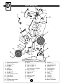
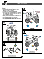
1. Vehicle Body (with Base)
2. Steering Column
3. Handlebar
4. Handgrip - 2
5. Knobs - 2
6. Microphone
7. Key Assembly
8. Cap Nut - 4
9. 6 Volt (4 Amp/hr.) Battery
10. Foam Pocket
11. 6 Volt Charger
12. Seat
13. Handlebar Wire Harness
14. Battery Retainer
10
37
35
36
33
19
14
32
16
16
13
11
18*
6
7
22
8
23
24
26
34
30
25
15. Grille
16. #8 x
7
/
8
" Screw - 2
17. #10 x 1
1
/
4
" Bolt - 2
18. #10 x
1
/
2
" Bolt
(Not required for all models)
19. #8 x
1
/
2
" Screw
20. #10 x
3
/
4
" Screw - 2
21. Lock Nut - 2
22. Collar - 2
23. Steering Linkage
24. Front Axle - 2
25. T-Slider
26. Washer - 2
27. Square Bushing - 3
28. Round Bushing - 2
29. Footrest - 2
30. Footrest Support
31. Front Wheel - 2
32. 25 Amp Fuse
33. Base
34. Headlight
35. U-Clip #2
36. U-Clip #1
37. #8 x 1” Screw - 2
Not Shown: Label Sheet
Parts Diagram
D
6

Battery Charging
E
7
WARNING
• The battery must be handled by adults only. The battery is heavy and contains sulfuric acid
(electrolyte). Dropping the battery could result in serious injury.
• Never allow children to charge the battery. Battery charging must be done by adults only.
A child could be injured by the electricity involved in charging the battery.
• Use of the wrong type battery, fuse or charger could cause a fire or explosion, resulting in
serious injury.
• Use of Power Wheels
®
components in products other than Power Wheels
®
vehicles could
cause overheating, fire or explosion.
• Read the cautions on the back panel of the battery.
• Never lift or carry the battery by the wires or connectors. This can damage the battery and
possibly cause a fire. Lift and carry the battery by the case only.
• Examine the battery, charger and their connectors for excessive wear or damage each time
you charge the battery. If damage or excessive wear is detected, do not use the charger or
the vehicle until you have replaced the worn or damaged part.
• Never alter this vehicle or its electrical system in any way. Alterations could cause a fire
resulting in injury and could also ruin the electrical system.

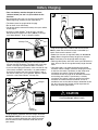
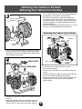
• Plug the charger into a standard 120 volt wall outlet.
Note: If power flow to the wall outlet is controlled by a
switch, make sure the switch is “ON”.
• Before first time use, charge the battery for at least 18
hours. Never charge the battery longer than 30 hours.
Note: The battery must be upright while charging.
• Recharge the battery after each use of your vehicle for at
least 18 hours. Do not charge the battery longer than 30
hours.
• Once the battery is charged, disconnect the charger
connector from the battery connector. Unplug the charg-
er from the wall outlet. The battery is now ready to be
installed in your vehicle. Please see the Battery
Installation section on page 16 for detailed instructions
on installing your battery. If your battery is already
installed in your vehicle, simply re-connect the battery
connector and motor harness connector and re-as-
semble the seat to the vehicle. Always remember to lock
the seat using the lock fastener or bolt to prevent chil-
dren from accessing the battery.
• If you are charging the battery for the first time, insert a
25 amp fuse into the battery. The battery will not charge
unless a 25 amp fuse in good condition is installed.
• If you are recharging your battery, make sure the 25 amp
fuse already installed in the battery is in good condition.
Use pliers to remove the fuse from the battery. Look at
the fuse to make sure it has not blown. Replace a blown
fuse with a new Power Wheels
®
25 amp fuse.
I
M
P
O
R
T
A
N
T
A
2
5
A
M
P
F
U
S
E
M
U
S
T
B
E
IN
S
T
A
LL
E
D
IN
T
O
P
O
F
B
A
T
T
E
R
Y
B
E
F
O
R
E
T
O
Y
W
ILL
R
E
C
H
A
R
G
E
O
R
O
P
E
R
A
T
E
25 Amp Fuse
1
3
• Plug the battery connector into the charger connector.
IMPORTANT NOTE! If you are recharging your battery,
you will first need to disconnect the battery connector
from the motor harness connector under the seat of
your vehicle.
Battery
Connector
Charger
Connector
Charger
Battery Charging
2
• Your new battery must be charged for at least
18 hours before you use it in your vehicle for the
first time.
• We recommend that you start charging your battery
before beginning assembly of your new vehicle.
• The battery must be upright while charging.
• Do not short circuit the battery.
• You do not need to remove the battery from your vehicle
to recharge it.
• Use only a Power Wheels
®
6 volt charger (120 VAC
60 Hz 6W with an output of 6 VDC (400mA) to charge
your Power Wheels
®
6 volt (4 Amp/hr.) battery.
8
CAUTION
Use the charger indoors only.
GOOD FUSE BLOWN FUSE

1
Steering Linkage
Front Axle
Front Axle
Vehicle Body
Fork
Axle/Linkage
Assembly
Steering
Linkage
Rivet Head
U-Clip #1
Peg
Slot
Ta b
Base
Base Platform #1
Front Axle
Short Leg
Long Leg
Pivot
Groove
Do Not Omit Any Steps
Assembly
3
F
9
2
1
• Using safety scissors, separate the U-clips from the
plastic connector. Dispose of the plastic connector.
• The U-clips and base platforms are marked with a
“1” or a “2”. Note the markings on the U-clips and
base platforms.
• Snap the tab on U-clip #1 into the slot in base
platform #1.
• Insert a #8 x 1" screw through the U-clip and into the
base platform.
• Tighten the screw with a Phillips screwdriver. Do not
over-tighten.
• Repeat this procedure to assemble U-clip #2 to base
platform #2.
• Position the steering linkage with the two rivet heads
facing up.
• Insert the short leg of a front axle up through the hole in
the pivot at one end of the steering linkage. Make sure
the axle’s long leg fits into the groove in the bottom of
the pivot.
Helpful Hint: You may need to tap the front axle with a
hammer to fit the long leg in the groove.
• Repeat this procedure to fit the remaining front axle
to the steering linkage.
• Fit a collar, solid end first, onto the short leg of a
front axle.
• Fit a cap nut onto the end of the axle's short leg.
• Tap the cap nut with a hammer to secure it on the end of
the front axle.
• Repeat this procedure to assemble the remaining collar
and cap nut to the other front axle.
4
Cap Nut
Collar
Front Axle
Short Leg
Steering Linkage
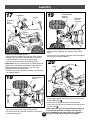
• Turn the vehicle body upside down.
• Fit the collars on the steering linkage assembly onto the
fork on the vehicle body as shown. Make sure the front
axles are towards the front of the vehicle and the
steering linkage is toward the rear of the vehicle.

Slot
Handlebar
Console
Pegs
Handlebar
Rectangular
Ta b
Headlight
Wheel Bushing
Wheel
Bushing
Front Axle
Washer
Front
Wheel
Vehicle Body
10
5
6
• Fit a wheel bushing into the rectangular opening in each
front wheel.
• Fit a washer onto one of the front axles.
• Slide a front wheel, bushing side first, onto the front axle.
Cap
Nut
Round
Bushing
• Slide a round bushing onto the front axle and press it
into the center of the front wheel.
• Fit a cap nut onto the end of the front axle.
• Tap the cap nut with a hammer to secure it on the front
axle.
• Repeat assembly steps 6 and 7 to assemble the other
front wheel to the other front axle.
• Position the vehicle body upright.
7
• Fit the rectangular tab on the back of the headlight into
the slot at the back of the handlebar console. Make sure
the pegs in the top corners of the headlight fit into
the handlebar console.
8
Assembly

Rectangular
Opening
Handlebar
Button End
Connector
End
Handlebar
Wire Harness
Handgrip
Handgrip
Handlebar
• Insert two #10 x
3
/
4
" screws through the slots in the
headlight and into the pegs in the handlebar.
• Press firmly on the front of the headlight and tighten
each screw with a Phillips screwdriver. Make sure there
is no gap between the headlight and the handlebar.
• Snap the knobs and key assembly into the handlebar
console.
• Bend the end of the microphone cord so that it forms
a "T".
• Insert the end of the microphone cord through the small
hole in the handlebar console.
• Fit the tab on the back of the microphone into the slot in
the handlebar console.
10
9
Assembly
• Fit a handgrip onto each end of the handlebar.
Helpful Hint: If the handgrips are difficult to slide onto the
handlebar, moisten the handgrips with warm water before
fitting them onto the handlebar.
11
11
12
Handlebar
Console
Slot
Key Assembly
Microphone
Knobs
T-End
Microphone
Cord
Press Here
• Insert the connector end of the handlebar wire harness
into the rectangular opening in the handlebar.
• Feed the handlebar wire harness through the handlebar.
• Push firmly on the button end of the handlebar wire har-
ness to snap it into the rectangular opening.

Steering
Column
Steering
Linkage
Hole
Guides
Steering
Column
Vehicle
Body
Square
Opening
Steering
Column
Square Bushing
13
• Turn the handlebar assembly upside down.
• Align the handlebar wire harness with the guides on the
underside of the handlebar and the guide at the bottom
of the headlight.
• Push firmly on the handlebar wire harness near each of
the guides to secure the wire in the underside of the
handlebar assembly.
• Set the handlebar assembly aside.
14
• Wipe the steering column with a paper towel to remove
any dirt or oils.
• Slide a square bushing onto the straight end of the steer-
ing column.
12
Assembly
• Insert the curved end of the steering column through the
square opening in the vehicle body.
• Rotate the square bushing
1
/
4
turn to slide it over the
tabs on the steering column and into the square opening
in the vehicle body.
• Turn the vehicle body on its side.
• Insert the curved end of the steering column into the
hole in the steering linkage. Make sure the steering
column is positioned between the guides on the
underside of the vehicle body.
15
16
Handlebar
Wire Harness
Handlebar
Headlight
Guides

13
Assembly
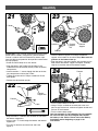
19
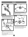
• Insert the wire connector on the main wire harness
through the large opening in the center of the vehicle
body.
• Plug the main wire harness connector and the handlebar
wire harness connector together.
20
• Position the vehicle body upright.
• Fit the bottom tabs on the grille into the slots in the front
of the vehicle body .
• Press firmly to snap the bottom tabs into the slots.
• Press firmly near the top of the grille to snap the top tabs
into the slots .
Please Note: You may need to flex the grille slightly to
fit it under the handlebar assembly. The grille may
have an additional tab. Press firmly in the middle of
the grille to snap the tab into the vehicle body.
2
1
Steering Column
Square
Bushing
Cap Nut
Handlebar
Hole
Handlebar
Wire
Harness
17
• Position the vehicle body upright.
• While fitting the handlebar onto the end of the steering
column, insert the end of the handlebar wire harness
through the hole in the front of the vehicle body.
• Fit a cap nut onto the end of the steering column.
Helpful Hint: You may need the help of another person to
support the curved end of the steering column near the
steering linkage to fit and secure the cap nut on the
straight end of the steering column.
• Tap the cap nut with a hammer to secure it on the end of
the steering column.
18
• Turn the vehicle body on its side.
• Fit a cap nut on the end of the steering column.
• Tap the cap nut with a hammer to secure it on the end
of the steering column.
Cap Nut
End of Steering
Column
Main Wire
Harness
Connector
Opening
Handlebar Wire
Harness
Connector
Grille
Bottom
Tabs
Top Tabs
Slots
1
2

22
23
• Align the holes in a footrest with the holes in one end of
the footrest support bar.
• Insert a #10 x 1
1
/
4
" bolt through the footrest and footrest
support bar.
• Fit a lock nut onto the end of the bolt and hand-
tighten it.
• Turn the vehicle body on its side.
• Using a Phillips screwdriver to steady the screw and
pliers to grip the lock nut, continue to tighten the bolt and
lock nut on each footrest.
• Turn the vehicle body upright.
One time assembly is now complete. Do not assemble
the seat until after you have charged and installed
the battery in the vehicle. Please refer to the Battery
Installation section beginning on page 16 for
instructions.
14
21
Please Note: If you have not removed the protective foam
pocket from the battery compartment, please remove it
and set it aside for later use. Remove any excess tape
from the vehicle and protective foam pocket and discard of
the tape properly.
• Stand the vehicle body on its rear wheels.
• Align the holes in the T-slider with the holes in the
underside of the vehicle body, directly under the battery
compartment.
• Insert three #8 x
1
/
2
" screws through the floor of the bat-
tery compartment and into the T-slider.
• Tighten the screws with a Phillips screwdriver. Do not
over-tighten.
• Position the vehicle body upright.
Assembly
Holes
Hole
Footrest
Footrest
Support Bar
Grooves
Footrest
Support
Footrest
Support
Bar
Footrest
• Insert the footrest support bar through the footrest
support at the bottom of the vehicle body. Make sure the
grooves on the footrest face up.
• Align the holes in the other footrest with the holes on the
other side of the footrest support and repeat assembly
step 22 on the other side of the footrest support.
T-Slider
Footrest
24

Label Decoration
15
Proper label application will help to keep the labels looking
their best!
• Please remove and discard the temporary labels
adhered to the sides of the vehicle.
• Wash your hands before applying the labels.
• Make sure the areas where the labels will be applied are
clean and dry. Wipe your vehicle with a clean, soft, dry
cloth to remove any dust or oils.
• For best results, avoid repositioning a label once it has
been applied to the vehicle.
• Apply the labels as shown in the illustrations.
• After applying each label, rub the label firmly with a
clean, dry cloth to make sure the label is adhered to
your vehicle.
G
Front View
1
2
8
10
11
12
5
6
7
Left Side
3
Right Side
4
15
15
1
14
4
9
9
2
2
2
2
3
16
13
Handlebar Console
Temporary
Label
Temporary
Label

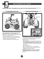
Battery Installation
16
Important Note: Use only a Power Wheels
®
6 volt
(4 Amp/hr.) battery with a Power Wheels
®
25 amp fuse
installed. Use of any other battery or fuse will damage
your vehicle. Make sure that you charge the battery for at
least 18 hours using the enclosed Power Wheels
®
6 volt
charger before operating your vehicle for the first time.
Charge the battery for at least 18 hours after each use of
the vehicle. Never charge the battery longer than 30 hours.
Failure to follow these instructions may damage your bat-
tery and will void your warranty.
1
H
• Position the battery retainer over the battery with the
ends of the battery retainer aligned with the screw holes
in the vehicle body.
• Insert two #8 x
7
/8" screws through the ends of the bat-
tery retainer and into the vehicle body.
• Tighten the screws with a Phillips screwdriver. Do not
over-tighten.
2
• Fit the battery into the protective foam battery pocket.
• Place the battery upright in the battery compartment.
Do
not place the battery in the battery compartment
without the protective foam pocket. Make sure the
battery connector extends toward the rear of the vehicle.
• Make sure a Power Wheels
®
25 amp fuse in good
condition is installed in the battery.
Battery
25 Amp
Fuse
Protective
Foam Pocket
Battery
Connector

Battery Installation
17
• Determine whether the seat on your vehicle is equipped
with a lock fastener or requires use of the #10 x
1
/2" bolt,
found in the Small Parts bag, to lock the seat. If your
vehicle seat is equipped with a lock fastener, please
properly dispose of the #10 x
1
/2" bolt.
3
4
• Plug the battery connector into the motor harness
connector.
Note: If the battery connector will not plug into the motor
harness connector, turn it over and try again! Do not force
the battery connector into the motor harness connector.
Motor
Harness
Connector
Battery
Connector
Seat Equipped With
Lock Fastener
Seat Requiring Use
Of #10 x
1
/2" Bolt
5
• Insert the tabs on the front of the seat into the slots in
the vehicle body.
Important Note: If the vehicle seat is equipped with a lock
fastener, make sure that the tab on the lock fastener is
aligned with the slot in the vehicle body.
• Press down on the back of the seat to snap the tabs on
the back of the seat into the slots in the vehicle body.
Seat
Ta b
Ta b
Ta b
Ta b
Lock
Fastener
Ta b
Lock Fastener Opening

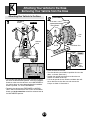
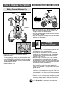
7
• To recharge or change the battery, unlock the vehicle
seat:
- If your vehicle seat is equipped with a lock fastener, use
a slotted screwdriver to rotate the lock fastener
1
/4 turn
to the unlocked position ( ).
- If your vehicle seat requires use of the #10 x
1
/2" bolt,
loosen the bolt using a Phillips screwdriver. Remove the
bolt and set it aside for re-assembly of the seat.
• Push in firmly on the back of the seat to release the tabs
on the seat from the slots in the vehicle body.
• Lift the seat to remove it from the vehicle body.
Ta b
Ta b
Push
Here
6b
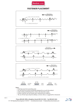
• Lock the seat to prevent children from accessing
the battery.
- If your vehicle seat is equipped with a lock fastener
(illustration 6a), use a slotted screwdriver to rotate the
lock fastener
1
/4 turn to the locked position ( ).
- If your vehicle seat requires use of the #10 x
1
/2" bolt
(illustration 6b), insert the bolt into the seat and tighten
it with a Phillips screwdriver. Do not over-tighten.
Seat
Lock
Fastener
Lock Fastener
Opening
Seat
Bolt
Hole
Hole
6a
LOCKED
Lock Fastener
18
Battery Installation

If a battery leak develops, avoid contact with the leaking
acid and place the damaged battery in a plastic bag. See
information below for proper disposal.
If acid comes in contact with skin or eyes, flush with
cool water for at least 15 minutes and call a physician.
If acid is internally ingested, give water, milk of magne-
sia or egg whites immediately. Never give emetics or
induce vomiting. Call a physician.
• Charge a new battery for at least 18 hours before first
use. Never charge the battery longer than 30 hours.
Overcharging or undercharging the battery may shorten
battery life and decrease vehicle running time.
• After the first charge, recharge the battery for at least
18 hours after each use. Never charge the battery longer
than 30 hours. Charge the battery after each use, regard-
less of how long the vehicle was used.
• The battery must be upright while charging.
• Do not allow the battery to run down completely before
charging.
• Charge the battery before storing the vehicle.
• Charge the battery at least once per month, even if the
vehicle has not been used.
• Leaving the battery in a discharged condition will ruin it.
• Always remove an old or exhausted battery from the
product. Battery leakage and corrosion can damage your
vehicle.
• Do not store the battery in temperatures above 75° F or
below -10° F.
• Prevent the battery from moving freely inside the battery
compartment. Always use the battery retainer and the
protective foam pocket to secure the battery in the bat-
tery compartment.
• Examine the battery, charger and their connectors for
excessive wear or damage each time you charge the bat-
tery. If damage is detected, do not use the charger or the
battery until you have replaced the worn or damaged
part.
• Attempting to charge the battery without a fuse or with a
blown fuse will not damage the battery, but the battery
will not charge. Check the fuse to make sure it is in good
condition each time you charge the battery.
• Your Power Wheels
®
battery is a sealed lead-acid
battery. It must be recycled or disposed of in an environ-
mentally sound manner.
• Do not dispose of the lead-acid battery in your regular,
household trash. The incineration, landfilling or mixing of
sealed lead-acid batteries with household trash is
prohibited by law in most areas.
• Return the battery to a federal or state approved lead-
acid battery recycler, such as a Power Wheels
®
authorized service center or a local seller of automotive
batteries. In Minnesota, call 1-800-348-0751 if further
disposal information is required. Contact your local
waste management officials for other information regard-
ing the environmentally sound collection, recycling and
disposal of lead-acid batteries.
WARNING
• Adult supervision is required. Children
do not have the judgement necessary to
avoid many accidents. Be sure that
children operating this vehicle can do so
safely and that they are supervised at
all times.
• Never use near steps, driveways, steep
inclines, roadways, alleys, swimming
pool areas or other bodies of water.
• Always wear shoes or sneakers when
operating this vehicle.
• Never allow more than one rider.
• The rider should sit on the seat when
the vehicle is in operation.
19
Rules
For Safe Driving
J
Battery Care
and Disposal
Battery Care
and Disposal
I
Care Disposal

10°
Incline should never be
more than 10°
5. Do not operate this vehicle with more than one rider,
seated in the seating area. A child who is not sitting on
the seat or who is standing on the vehicle could fall off,
cause a tip-over or block the driver’s view. A child could
be seriously injured.
Rules for Safe Driving
6. Always wear shoes or sneakers when operating this
vehicle.
7. Never put anything near any moving parts. Rotating
parts such as motors, gear boxes and wheels can snag
fingers, hair, etc., causing serious injury. Do not allow
operation of the vehicle when it is on its side or in an
upside-down position.
8. Do not operate the vehicle near flammable vapors
(gasoline, paint thinner, acetone, liquid wax, etc.).
The vehicle’s electrical switches, like most electrical
switches, emit an internal spark when first turned on
or turned off. The presence of flammable liquids or
vapors could cause an explosion or a fire. Keep all
flammable products in tightly sealed containers and
away from the vehicle.
9. Do not allow a child to operate the vehicle without
proper adult supervision. To prevent unsupervised use
of the vehicle, disconnect the motor harness from the
battery when the vehicle is not in use.
To disconnect the motor harness connector and
battery connector:
• Unlock the seat and remove it to access the battery.
• Unplug the motor harness connector from the battery
connector.
• Re-assemble the seat to your vehicle.
Important Note: Always remember to lock the seat to
prevent children from accessing the battery.
Teach Safety Rules to Children
While children can quickly develop the skill necessary to
drive this vehicle, it is important to remember that their
judgement skills are still very immature. Unsupervised dri-
ving by children can lead to serious injury. Before children
use the Rock & Roll, an adult should carefully evaluate
the driving area as well as the children’s skill level and
ability to drive this vehicle safely. Children are not always
able to recognize or anticipate hazards, even when they
have been taught about them. There is no acceptable sub-
stitute for adult supervision.
Teach appropriate safety rules to your child before allow-
ing operation of this vehicle. These rules should also be
reviewed with neighborhood children or other playmates
who want to drive this vehicle.
1. Do not allow any child to drive the vehicle in the street
or near moving (motorized) vehicles.
2. Do not allow any child to drive near bodies of water
(such as pools or creeks), obstructions (such as furni-
ture, low tree limbs or play equipment), or drop-offs
(such as stairs or decks).
3. Do not allow any child to drive the vehicle in the dark.
A child could encounter unexpected obstacles and have
an accident. Operate the vehicle only in the daytime or
in a well-lit area.
4. Teach your child to avoid driving on steep inclines or
slopes. Restrict your child’s driving to areas that are
fairly level with gentle inclines or slopes of no more
than 10°.
• While driving down a steep slope, the vehicle may
gain unsafe speed, even if the handlebar button is
released to stop.
• While driving across a steep slope, the vehicle may
tilt and tip over. The wheels could lose traction,
causing the vehicle to slip.
• While driving up a steep incline, the motor may stop
and the vehicle could roll backwards at an unsafe
speed.
Motor
Harness
Connector
Battery
Connector
20
Page is loading ...
Page is loading ...
Page is loading ...
Page is loading ...
Page is loading ...
Page is loading ...
Page is loading ...
Page is loading ...
Page is loading ...
Page is loading ...
Page is loading ...
Page is loading ...
-
 1
1
-
 2
2
-
 3
3
-
 4
4
-
 5
5
-
 6
6
-
 7
7
-
 8
8
-
 9
9
-
 10
10
-
 11
11
-
 12
12
-
 13
13
-
 14
14
-
 15
15
-
 16
16
-
 17
17
-
 18
18
-
 19
19
-
 20
20
-
 21
21
-
 22
22
-
 23
23
-
 24
24
-
 25
25
-
 26
26
-
 27
27
-
 28
28
-
 29
29
-
 30
30
-
 31
31
-
 32
32


Ask a question and I''ll find the answer in the document
Finding information in a document is now easier with AI
Related papers
Other documents
-
Kawasaki PW Lil Kawasaki User manual
-
Hot Wheels B9272 User manual
-
Hasbro Tyke Bike Operating instructions
-
 Hampton Bay FS/PS9212HA/TCO Operating instructions
-
Polaris Hammer S/Hammer 8-Ball/Vegas Jackpot/Vegas 8-Ball/High-Ball/Victory Judge Owner's manual
-
Victory Victory Hammer S / Vegas / Vegas 8-Ball / Vegas High-Ball / Gunner Owner's manual
-
Victory Motorcycles Victory Vision Tour / Ness Signature Tour Owner's manual
-
Victory Motorcycles Gunner INTL Owner's manual
-
-
