Page is loading ...

Use & Care Guide
Liquid Propane Gas (LPG) Grill
®
Kenmore Model Number: 119.16301800
KmartItem Number: 640-810979-112
• Safety
• Assembly
• Use and Care
• Cooking Guide
• Espa_ol, Pg. 30
• Parts and Service
Call us first if you have any problem with this
product. We can help you with questions about
assembly and grill operation or if there are
damaged or missing parts when you unpack this
unit. Please call before returning to the store.
1-800-933-0527
8:30am-5:OOpm CST, Non thru Friday
Note to Assembler/Installer :
Leave this guide with the consumer.
Note to Consumer :
Keep this guide for future reference.
Record Your Serial Number :
(See silver CSA Plate inside of right door)
Date of Purchase :
Attach Your Sales Receipt Here :
Failure to comply with these instructions could
result in a fire or explosion that could cause
serious bodily injury, death or property damage.
Read this entire guide before using your
grill to ensure the grill is properly assembled,
installed and maintained, whether it was
assembled by you or someone else.
Use your grill at least 2 feet away from
any wall or surface. Use your grill at least 2 feet
away from combustible objects that can melt or
catch fire (such as vinyl or wood siding, fences
and overhangs) or sources of ignition including
pilot lights on water heaters and live electrical
appliances.
THIS GAS APPLIANCE IS DESIGNED FOR
OUTDOOR USE ONLY.
Combustion byproducts produced when using
this product contain chemicals known to the
State of California to cause cancer, birth
defects, or other reproductive harm.
Sears, Roebuck and Co., Hoffman Estates, IL 60179 U.S.A. www.sears.com
!

Primary Safety Warnings ................................... 1-3
Warranty Information ............................................ 2
Pre-Assembly Instructions .................................... 3
Part Diagram and Lists ...................................... 4-9
Assembly Instructions ................................... 10-18
Use & Care Instructions ................................ 19-27
Frequently Asked questions .................................. 28-29
Spanish Guide ...........................................................30-58
Repair Protection Agreement ................................... 59
Sears Paresand Service Information .......................60
IF YOU SHELL GAS:
Shut off gas to the appliance.
Extinguish any open flame.
Open lid.
If odor continues, keep away
from the appliance and immediately
call your gas supplier or your fire
department.
Kenmore 1-Year Full Warranty
If this grill fails due to a defect in material or workmanship
within one year from the date of purchase, call
1-800-4-HY-HOIE® to arrange for
free repair (or replacement if repair proves impossible).
Limited Warranty on Selected Grill Parts
From the date of purchase for the time periods listed
below, the following specific grill parts will be
replaced free of charge if they rust through. After
the first year from the date of purchase you must
pay the labor cost to have them installed.
• Stainless Burners 10 Years
• Stainless Parts 3 Years
• Painted Parts 2 Years
• Cooking Grids 2 Years
• Heat Diffuser 2 Years
All warranty coverage excludes igniter batteries and
grill part paint loss or surface rusting, which are
either expendable parts that can wear out from
normal use in less than a year, or are conditions that
can be the result of normal use, accident or
improper maintenance.
All warranty coverage is void if this grill is ever used for
commercial or rental purposes.
All warranty coverage applies only if this grill is used in the
United States.
This warranty gives you specific legal rights, and you may
have other rights which vary from state to state.
Sears, Roebuck and Co.,
Hoffman Estates, IL
• Do not store or use gasoline or other
flammable liquids or vapors in the
vicinity of this or any other appliance.
• An LP cylinder not connected for use
shall not be stored in the vicinity of this
or any other appliance.
• NEVER use your gas grill in a building,
garage, porch, shed, breezeway or any
other enclosed area,
• NEVER obstruct the flow of ventilation
air around your gas grill cabinet,
• DO NOT leave children and pets
unattended in the area when the grill is
in operation.
• ENSURE the grill is on a level surface
when in operation and the locking casters
are locked, Push down on locking levers so
that wheels don't move,
• NEVER attach an unregulated gas line
to this appliance.

DONOTlightthisgrillwithoutfirstreading
theLightingInstructions.
DONOTlightthisgrillwithoutcheckingthe
burnertubesforblockagethatcouldhave
occurredduringshipment.SeetheCleaning
andHaintenanceInstructions.
Theinstallationmustconformwithlocalcodesor,
intheabsence of local codes, with either the
National Fuel Gas Code, ANSI Z223.1/NFPA 54,
or CAN/CGA B149.1, Natural Gas and Propane
Installation Code, or Propane Storage and
Handling Code, B149.2.
• DO NOT use any type of charcoal in this grill.
• DO NOT operate the main burners and back
burner at the same time. (If Equipped)
• ALWAYS inspect the grease tray before each
use. Remove and clean as necessary.
All electrical accessories (such as a rotisserie or
light) must be electrically grounded in accordance
with local codes, or in the absence of local codes,
with the National Electrical Code, ANSI/NFPA 70,
or the Canadian Electrical Code, CSA C22.1. Keep
any electrical cords away from hot surfaces.
This outdoor cooking gas appliance is not
intended to be installed in or on boats or
recreational vehicles.
Liquid Propane Gas (LPG) grills must be used with
the liquid propane gas regulator assembly supplied.
Natural Gas grills must be used with natural gas
only. Any attempt to convert the grill from one fuel
type to another is extremely hazardous.
ALWAYS keep the gas hose assembly away from
any heated surface and dripping grease, Avoid
unnecessary twisting of the hose, Visually
inspect the hose prior to each use for cuts,
cracks, excessive wear, or other damage, Do not
use the gas grill if the hose appears damaged.
Call Sears at 1-800-4-HY-HOME®
(1-800-469-4663) for a Kenmore replacement gas
hose assembly.
PRE-ASSEMBLY
• Tools required for assembly include:
•Protective work gloves and eyewear
• Phillips head screwdriver (included in hardware
pack)
• Two people will be necessary to assemble the
larger parts of the grill.
• Lay a cardboard sheet on the floor and use as a
work surface to protect floor and grill parts from
scratches.
• Once all parts are removed and unpacked, use the
Hardware and Part Diagrams to ensure all items are
included and free of damage.
• Do not assemble or operate your grill if something
appears damaged. If you have damaged or missing
parts, or questions during assembly, call
1-800-933-0527 8:30am-5:00pm CST, Honday
through Friday.

PART#
SB0064
SB0027
FEOI05
SBO005
SB0085
SBO016
SEOI23D-O02
BO6WIB-6-C7
SEO007
FE0014N
SE9049D-O01
BO6WIB-6-C5
SBOll4
PART DESCRIPTION
QTY PURPOSE OF PART
Phillips Head Bolt,M6x35mm 4PCS Attaches Cabinet Front Crossbar
Phillips Head Bolt,M6xl6mm
Install Casters, Attaches Firebox Assembly, Side
24PCS Burner Assembly and Side Shelf Assembly
M6xl.OT Plastic Washer
Attach the Firebox Assembly to the Cabinet
4PCS Assembly
Lock Washer, M6
There are 8 Washers used with some Phillips head
8PCS bolts
Phillips Head Bolt,M4x8mm 22PCS
Attaches the Door Top Brackets to the Cabinet
Assembly, Attaches Side Burner Control Panel, Side
Shelf Assembly, Side Burner Valve, Cabinet Door
Stop
Lock Washer, M4
There are 14 Washers used with most Phillips
14PCS head bolts
"S"-Hook 3PCS Utensil Hooks
Cabinet Door Stop
1PC Secures Cabinet Door in closed Position
Battery Size AA
1PC For the Electronic Igniter
Phillips Head Screwdriver
1PC To Screw All the Bolts
Cotter Pin
Attaches Grease Cup Bracket Support to Grease
2PCS Tray
Door Top Brackets (L/R)
2PCS Attaches to Cabinet to support the Door Pins
Washer M4
There are 4 Washers used with Towel Bar Phillips
4PCS head bolts

Phillips Head Bolt M6x35mm
Qty: 4
Part # SB0064
Plastic Washer M6xl,0T
Qty: 4
Part # FE0105
"S"- Hook
Qty: 3
Part # SE0123D-002
Phillips Head Bolt M6x16mm
Qty: 24
Part# SB0027
Lock Washer M6
Qty: 8
Part # SB0005
Battery Size: AA
Qty: 1
Part # SE0007
Phillips Head Bolt M4x8mm
Qty: 22
Part # SB0085
Lock Washer M4
Qty: 14
Part # SB0016
Cotter Pin
Qty: 2
Part # SE9049D-001
Washer M4
Qty: 4
Part # SB0114
Door Top Brackets (L/R)
Qty: 2
Part# B06WlB-6-C5
Cabinet Door Stop
Qty: 1
Part# B06WlB-6-C7
Phillips Head Screwdriver
Qty: 1
Part # FE0014N


KEY DESCRIPTION PART# QTY
A Hood Assembly
AI Hood LeftSide Panel CAOO44-L 1
A2 Hood Right Side Panel CA0044-R 1
A3 Thermometer Seat CA0045D-002 1
A4 Thermometer SE0076 1
A5 Hood Bolt B06WlB-6-A5 2
A6 Hood Handle Seat - Right B06WlB-6-A6 1
A7 Hood Handle Seat- Left B06WlB-6-A7 1
A8 Hood Handle Heat Insulator FE0010 2
A9 Silicon Stopper FE0001M 4
A10 Hood Outer Panel B070E4-A10 1
All Hood Inner Panel B070E4-All 1
A12 Hood Handle B070E4-A12 1
B Firebox Assembly
B1 Firebox Rear Upper Panel B070E4-B1 1
B2 Firebox Rear Panel B070E4-B2 1
B3 Warming Rack SE0154 1
B4 Cooking Grate-11.6" width CI0018 2
B5 Heat Diffuser SA0619 3
B6 Main Burner Bracket B070E4-B6 1
B7 Main Burner B06WlB-6-B7 3
B8 Firebox Left Side Panel B06WlB-6-B8 1
B9 Firebox Right Side Panel B06WlB-6-B9 1
B10 Main Burner Electrode B06W1B-6-B10 3
Bll Firebox Bottom Panel B070E4-Bll 1
B12 Grease Tray SA0640-3 1
B13 Cotter Pin SE9049D-001 2
B14 Grease Cup Bracket SE0147 1
B15 Grease Cup SA0375 1
B16 Firebox Front Panel B070E4-B16 1
B17 Firebox Front Heat Shield B070E4-B17 1
B18 Gas Manifold Assembly SC0047 1

KEY DESCRIPTION PART# QTY
B19 Main Burner Control Panel B070E4-R-B19 1
B20 Control Knob Seat B06W1B-6-B20 3
B21 Control Knob FE0090D-001 3
B22 Electronic Igniter Button SE0131- A 1
B23 Electronic Igniter SE0131 1
B24 Electronic Igniter Wire Set B070E4-B24 4
B25 Regulator and Hose Assembly SE0148 1
C Cabinet Assembly
C1 Cabinet Rear Panel B070E4-C1 1
C2 Cabinet Assembly B070E4-C2 1
C3 Regulator and Hose Support Ring B06W1B-6-C3 1
C4 Leg Caps FE0093 4
C5 Door Top Bracket Set B06W1B-6-C5 2
C6 Cylinder Support Ring SE0085D-002 1
C7 Cabinet Door Stop B06W1B-6-C7 1
C8 Cabinet Toe Plate B070E4-C8 1
C9 Cabinet Front Crossbar B070E4-C9 1
C10 Magnetic Door Stop SE0150 2
Cll Left Door B070E4-R-Cll 1
C12 Right Door B070E4-R-C12 1
C13 Door Spring Pin SE0149 2
C14 Door Pin B06W1B-6-C14 2
C15 Cabinet Door Handle B06W1B-6-C15 2
C16 Manual Igniter Stick SE0108D-001 1
C17 Condiment Basket SE9027 1
C18 Locking Standard Caster B06W1B-6-C18 1
C19 Standard Caster B06W1B-6-C19 1
C20 Locking Swivel Caster B06W1B-6-C20 1
C21 Swivel Caster B06W1B-6-C21 1
D Side Burner Assembly
D1 Side Burner Cover Pin B06WIB-6-D1 1
D2 Side Burner Cover SA0390 1
D3 Side Burner Rack SE0084 1

KEY DESCRIPTION PART# QTY
D4 Side Burner Stopper SB0045D-001 2
D5 Side Burner Inner Frame B06WIB-6-D5 1
D6 Towel Bar Handle B06WlB-6-D6 1
D7 Side Burner Outer Frame Assembly B070E4-D7 1
D8 Side Burner Electrode B06WlB-6-D8 1
D9 Side Burner Valve B06WlB-6-D10 1
D10 Side Burner B06WlB-6-D9 1
Dll Side Burner Control Panel B070E4-R-Dll 1
D12 Control Knob Seat B06WlB-6-B20 1
D13 Control Knob FE0090D-001 1
E Side Shelf Assembly
E1 Side Shelf Frame Assembly B06WlB-6-E1 1
E2 Towel Bar Handle B06WlB-6-D6 1
E3 Side Shelf Control Panel B070E4-R-E3 1
E4 "S" Hooks SE0123D-002 3

!!
Remove Firebox from Cabinet
[] Unscrew and discard the 6 Phillips Head Bolts and Washers from the corner holes of the cabinet.
Remove the crossbar.
[] Carefully lift the cabinet up from the firebox and set on cardboard. Remove all foam packing from
cabinet.
[] Cut fastening straps on lid handle. Raise lid and remove and unpack parts inside firebox.
Crossbar
Install Control Knobs and Casters
[] Push the Control Knobs onto the valve stems. See Inset 1,
[] Place the Cabinet Assembly upside down and using 16 Phillips Head Bolts (M6x16mm) attach the 4
Casters to the Cabinet Assembly bottom. Use care to install each Caster into the correct position.
See Inset 2.
Inset 1
Phillips Head Bolt M6x16mm
qty: 16
r
Main Burner Control knob
qty: 3
Standard Caster
Swivel Caster
Locking Standard Caster
Inset 2
Locking Swivel Caster
lO

N nstall Cabinet Front Crossbar and Door Top Brackets
[] Attach the Cabinet Front Crossbar to the Cabinet using 4 Phillips Head Bolts (M6x35mm) and 4 Lock
Washers (M6),
[] Attach Door Top Brackets labeled L and R to the Cabinet using 4 Phillips Head Bolts (M4x8mm),
Phillips Head Bolt: M6x35mm
Qty: 4
Phillips Head Bolt M4x8mm
Qty: 4
©
Lock Washer M6
qty: 4
Door Top Brackets (L/R)
Qty: 2
Attach Doors to Cabinet
[] Push down on top hinge pin to insert the Left and Right Doors into the cabinet. See Inset
illustrations.
1!

Hang Condiment Basket and attach Cabinet Door Stop
[] Hang Condiment Basket on the inside of cabinet Right Door, See Inset 1.
[] Attach the Cabinet Door Stop to the front of cabinet bottom using 2 Phillips Head Bolts (M4x8mm),
See Inset 2.
Phillips Head Bolt M4x8mm
qty: 2
Inset i
Cabinet Door Stop
qty: 1
Inset 2
Attach Firebox to Cabinet
[] Place the firebox onto the cabinet frame with regulator hose and side burner ignition wire
hanging inside of the cabinet, We recommend using 2 people to lift the firebox.
[] Line up the holes and attach the firebox to the cabinet frame using 4 Phillips Head Bolts (M6xl6mm)
and 4 Washers (M6x!.0T).
Hint: You may need to slide the Firebox Assembly forward, backward, or lift slightly for
the bolt holes to properly line up.
Phillips Head Bolt M6x16mm
qty: 4
M6xl.0T Plastic Washer
qty: 4
]2

Cotter Pin
qty: 2
Install Grease Tray, Grease Cup Bracket and Grease Cup
[] Insert the Grease Tray along two sides of the firebox from the back underneath the firebox,
See Inset 1
[] Attach the Grease Cup Bracket to the bottom of the Grease Tray using 2 Cotter Pins as shown
The Cotter Pins in the bracket are towards the front of the grill See Insets2 and 3
[] Install the Grease Cup into the Grease Cup Bracket, inserting it from the front of the cabinet
See Inset 4
I._) °__ --_
Inset 1 Inset 2 Inset 3 Inset 4
Xnstall Towel Bar Handles, Utensil Hooks, Side Panels.
[] Use 2 Phillips Head Bolts (M4x8mm), 2 Lock Washers (M4), and 2 Washers (M4) to attach a Towel
Bar to the side burner frame. Use 3 Phillips Head Bolts (M4xSmm) and 3 Lock Washers (M4) to
attach the Side Burner Control Panel to the side burner frame. See Insets 1 and 2.
[] Slide 3 Utensil Hooks onto the second Towel Bar and use 2 Phillips Head Bolts (M4x8mm), 2 Lock
Washers (M4), and 2 Washers (M4) to attach the Towel Bar to the side shelf. Use 3 Phillips Head
Bolts (M4xSmm) and 3 Lock Washers (M4) to attach the Side Shelf Front Panel to the side shelf
frame. See Insets 3, 4, and 5.
Phillips Head Bolt M4x8mm
Qty: 10
Lock Washer: M4
Qty: 10
"S"- Hook
Qty: 3
Washer M4
Qty: 4
Inset 1 Inset 2 Inset 5 Inset 4 Inset 3
13

install Side Burner Frame to Firebox.
[] Unscrew the 2 Phillips Head bolts ¼" from the upper left and right corner holes in the left side of the
firebox as shown in Inset 1. The bolts extending out of the firebox sides are to attach the side
burner frame.
[] Slide the upper holes of the side burner frame over the heads of the 2 Phillips Head Bolts and drop
down.
[] Use 2 Phillips Head Bolts (M6x16mm) and 2 Lock Washers (M6) to attach the lower holes in the side
burner frame to the firebox as shown in Inset 2. Tighten the upper bolts after the 2 lower bolts are
tight.
Inset 1
Phillips Head Bolt M6x16mm
Qty: 2
©
Lock Washer M6
qty: 2
Inset 2
Install Side Burner Valve
[] Detach side burner ignition wire from the regulator hose if they are taped together.
[] Insert the side burner valve stem up through the hole in the Side Burner Control Panel. See
Inset 1.
[] Center the side burner valve in the side burner tube. See Inset 2.
[] Secure the side burner valve stem to the Side Burner Control Panel using 2 Phillips Head Bolts
(M4x8mm). See Inset 3.
Phillips Head Bolt M4x8mm
Qty: 2
nset 3
Inset 2
Inset 1
14

Attach Side Burner Control Panel to Hain Control Panel
[] Use 2 Phillips Head Bolts (M4x8mm) and 2 Lock Washers (M4) to attach the Side Burner
Control Panel to the firebox as shown.
Phillips Head Bolt M4x8mm
Qty: 2
©
Lock Washer: M4
Qty:2
Attach Side Burner Control Knob and Side Burner Ignition Wire
[] Slide the side burner ignition wire through the hole located in the lower left front corner of the
Firebox Assembly and over the side burner igniter connector. See Insets 1 and 2.
[] Push the Control Knob onto the valve stem. See Inset 3.
Side Burner Control Knob
qty: 1
Inset 2
Inset 3
1
Inset 1
15

Install Side Shelf Frame to Firebox.[] Unscrew the 2 Phillips Head bolts 1/4"from the upper left and right corner holes in the right side of
the firebox as shown in Inset 1. The bolts extending out of the firebox sides are to attach the side
shelf frame.
[] Slide the upper holes of the side shelf frame over the heads of the 2 Phillips Head Bolts and drop
down.
[] Use 2 Phillips Head Bolts (M6x16mm) and 2 Washers (M6) to attach the lower holes in the side
shelf frame to the firebox as shown in Inset 2. Tighten the upper bolts after the 2 lower bolts are
tight.
[] Use 2 Phillips Head Bolts (M4x8mm) and 2 Lock Washers (M4) to attach the lower holes in the Side
Shelf Front Panel to the firebox. See Inset 3,
Inset 1 Inset 2
Phillips Head Bolt M6x16mm
Qty: 2
©
Lock Washer: M6
Qty: 2
Phillips Head Bolt M4x8mm
Qty: 2
©
Lock Washer M4
Qty: 2
Inset 3
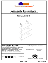
_I_ Install Heat Diffuser, Cooking Grates, and Warming Rack
[] Place the Heat Diffuser into the firebox between the ridges in the front and back panels. See Inset
1,
[] Place the Cooking Grates into the firebox. The grate bottoms have a small knob on each corner. See
Inset 2,
[] Insert the Warming Rack into the holes of firebox side panels as shown, See Inset 3.
Inset 1 Inset 3 Inset 2

/_ Place and Secure LP Cylinder into the Cabinet[] Hook the ends of the Cylinder Support Ring into the two holes in the left front and rear legs.
See Inset 1,
[] Place the LP cylinder down into the tank support hole in the bottom of the cabinet. Ensure the valve
faces to the front. Wrap the Cylinder Support Ring around the top of the tank and hook to secure the
LP cylinder in place, See Inset 2.
[] Unscrew the bolt and nut located on the front of the left side cabinet panel. Attach the regulator
hose support ring, located on the regulator hose, to the left side cabinet panel using the same bolt
and nut. See Inset 3,
Do Not Hook Up the LP Cylinder to the Regulator Assembly at this time.
Inset 1
Inset 2
Inset 3
Install Battery
[] Unscrew the electronic igniter cap. Place the "AA" Battery into the igniter with the positive (+) end up.
Screw the electronic igniter cap back into place,
Battery (Size AA)
qty: 1
]7

_1_ Congratulations - Assembly is now complete!
[] Remove any additional labels or packing material from the grill except the CSA label. Be sure to
clean all foam packing material out of all areas.
[] Please proceed to and read the remaining sections of the Use & Care Guide prior to hooking up
your LP cylinder or operating your grill.
[] To transport grill, grasp Towel Bar Handle on the end of the side shelf for easier mobility.
0
• 0 0 @
18

CORRECT LP GAS TANK USE
• LP gas grill models are designed for use with a
standard 20lb. (9.1kg) Liquid Propane Gas (LP Gas)
tank, which is not included with the grill. Never
connect your gas grill to an LP gas tank that exceeds
this capacity. A tank of approximately 12" (305ram)
in diameter by 18-1/2" (472mm) high is the
maximum size LP gas tank to use. You must use an
"OPD" gas tank which offers a listed Overfill
Prevention Device. This safety feature prevents
tanks from being overfilled which can cause
malfunction of the LP gas tank, regulator and grill.
• The LP gas tank must be constructed and marked in
accordance with the Specifications for LP-Gas
Cylinders of the U.S. Department of Transportation
(D.O.T.) or the National Standard of Canada,
CAN/CSA-B339, Cylinders, Spheres and Tubes for
Transportation of Dangerous Goods; and
Commission, as applicable.
• The LP gas tank must have a shutoff valve terminating
in a LP gas supply tank valve outlet that is compatible
with a Type 1 tank connection device. The LP gas tank
must also have a safety relief device that has a direct
connection with the vapor space of the tank.
• The tank supply system must have a means for
vapor withdrawal.
• The LP gas tank used must have a collar to protect
the tank valve.
• Never connect an unregulated LP gas tank to your
gas grill. The gas regulator assembly supplied with
your gas grill is adjusted to have an outlet pressure
of 11"water column (W.C.) for connection to an LP
gas tank. Only use the regulator and hose assembly
supplied with your gas grill. Replacement
regulators and hose assemblies must be those
specified by Sears. See the Parts List.
Have your LP Gas dealer check the release valve
after every filling to ensure it remains free of
defects. Always keep the LP gas tank in an upright
position. Do not subject the LP gas tank to excessive
heat.
• Never store an LP gas tank indoors. If you store your
gas grill indoors, always disconnect the LPgas tank first
and store it safely outside.
• LP gas tanks must be stored outdoors in a
well-ventilated area and out of the reach of children.
• Disconnected LP gas tanks must not be stored in a
building, garage, or any other enclosed area.
• The regulator and hose assembly can be seen after
opening the door and must be inspected before each
use of the grill. If there is excessive abrasion or wear
orifthe hose is cut, it must be replaced priorto using
the grill again.
• Never light your gas grill with the lid closed or
before checking to ensure the burner tubes are fully
seated over the gas valve orifices.
• Never allow children to operate your grill. Do not
allow children or pets to play near your grill.
19
• Use of alcohol or drugs may impair the ability
to assemble and operate the appliance.
• Keep a fire extinguisher readily accessible. In
the event of an oil or grease fire, do not attempt
to extinguish with water. Use a Type B extinguisher
or smother with dirt, sand, or baking soda.
• In the event of rain, cover the grill and turn off
the burner and gas supply.
• Use your grill on a level, stable surface and ensure
the locking casters are locked before use.
• Do not leave the grill unattended when in use.
• Do not move the appliance when in use.
• Allow the grill to cool before moving or storing.
• Do not use your grill as a heater.
This grill is not intended to be installed in or on
recreational vehicles and/or boats.
A. Do not store a spare LP gas tank under or
near this appliance.
B. Never fill the tank beyond 80 percent full;
C. If the information in "(a)'and "(b)" is not
followed exactly, a fire causing death or
serious injury may occur.
Use your grill at least 2 feet away from any
wall or surface. Use your grill at least 2 feet
away from combustible objects that can melt or
catch fire (such as vinyl or wood siding, fences
and overhangs) or sources of ignition including
pilot lights on water heaters and live electrical
appliances.
Never use your gas grill in a building, garage,
porch, shed, breezeway, or any other enclosec
area.
Never obstruct the flow of ventilation air
around your gas grill housing.

Notes about LP Gas Tank Exchange Programs
• Many retailers that sell grills offer you the option of
replacing your empty LPgas tank through an
exchange service. Use only those reputable
exchange companies that inspect, precision fill, test
and certify their tanks. Exchange your tank only for
an OPD safety feature equipped tank as described
in the LPgas tank section of this manual,
• Always keep new and exchanged LPgas tanks in an
upright position during use, transit or storage.
• Leak test new and exchanged LP gas tanks BEFORE
connecting one to your grill.
How to Leak Test your LP Gas Tank
For your safety:
• All leak tests must be repeated each time your LP gas
tank is exchanged or refilled.
Do not smoke when checking for gas leaks.
• Do not use an open flame to check for gas leaks.
Your grill must be leak tested outdoors in a
well-ventilated area, away from ignition sources such
as gas fired or electrical appliances. During the leak
test, keep your grill away from open flames or
sparks.
• Do not use household cleaning agents as damage to
gas assembly components can occur.
[] Use a clean paintbrush and a 50/50 mild soap and
water solution.
FIBrush soapy solution onto the LP gas tank in the areas
indicated by the arrows. See diagram.
I--IIf growing bubbles appear do not use or move the LP
Gas tank. Call an LPgas supplier or your fire
department.
Regulator and LP Cylinder Connections
The gas pressure regulator provided with this
outdoor cooking appliance must be used. This
regulator is set for an outlet pressure of 11
inches water column.
Regulator:
Your regulator is equipped with a Q.C.C. Type 1
quick connect system. It will not allow gas to flow
until a positive seat has been made. It has a
thermal element that will shut off the gas flow if
the temperature reaches 240 degrees F (115
degrees C), It also has a flow-limiting device that
will restrict the flow of gas to 10 cubic feet per
hour (0.28 cubic meters per hour).
TO CONNECT THE CYLINDER TO THE
REGULATOR AND HOSE
1. Be sure the LP cylinder is "OFF" by turning the
hand wheel clockwise until it stops.
2. Place the cylinder into the base cabinet shelf of
the grill with the valve facing outward and secure
with the cylinder support ring.
3. Be sure all burner controls are turned to the
"OFF" position.
4. Remove the safety cap from the cylinder valve.
5. Center the nipple of the regulator into the
cylinder valve.
6. Turn the black nut clockwise until it stops.
Hand Tighten Only. Do Not Use A Wrench.
If growing bubbles appear do not use or move
the LP Gas tank. Contact an LP gas Supplier or
your fire department!
\
CAUTION: When the appliance is not in use
the gas must be turned off at the tank.
20
/