
IRIS-RS232-Short manual-1a
RS-232
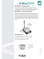
IRIS-RS232 – Getting started
IRIS-RS232 is part of the IRIS series and is developed for relaying data via radio from
systems with a RS-232 interface to other systems connected to IRIS products. The IRIS series
contains several models that provide solutions to all kinds of applications. All IRIS models can
communicate with each other via radio, in pairs or in more complex radio networks.
Getting started
Connect the serial interface (only Rx, Tx and signal ground are needed)
Connect the power supply. The polarity of the power does not matter.
Place the IRIS-RS232 so that the antenna is not shielded.
Avoid metal plating close to and between the antennas.
IRIS-RS232 – Product description
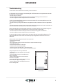
IRIS-RS232 can be used with systems with a RS-232 interface. The most common use of IRIS-
RS232 is a pair of IRIS-RS232 that relays data between two systems. This is however not the
only application where an IRIS-RS232 can be used. A PC with an IRIS-RS232 can be used for
monitor and control other systems. Commands can be sent to machines with serial interface via
IRIS-RS232 and IRIS-RS485, electrical signals can be controlled via IRIS-IO, data can be stored
in a database via an IRIS-CUW and data can be sent to the PC from all the other units. With
functions like timers, counters and text matching the IRIS-RS232 can setup to fit many different
applications.
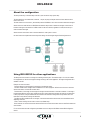
Serial interface
Power
IRIS-RS232 - D-sub
2. Rx - Receive data
3. Tx - Transmitt data
5. Ground

IRIS-RS232
2
About the configuration
The setup on delivery is a standard setup made for a quick start and an easy system setup.
The serial interface is set to 9600 baud, 8 data bits, 1 stop bit, no parity, half duplex and end of data is detected with a
timeout set to 50 ms.
The radio channel is set to channel 1 (433.075 MHz) and the IRIS-RS232 is set to send and receive broadcast messages.
All data sent to the serial interface on IRIS-RS232 will with this setup be sent as broadcast messages over the radio. A
broadcast message can be received of all IRIS-modules on the same channel, regardless of model, that are set up to
receive broadcast messages.
All data received via the radio is sent to the serial interface for other system to collect.
No other functions are implemented in this setup but all settings can be changed using the IRIS-Configuration tool.
Using IRIS-RS232 for other applications
The IRIS products are made for monitoring and controlling external system. The standard setup is of course not suitable
for all applications so feel free to change the settings according to the current application. The original configuration file is
available on the CD.
Examples on what can be done:
· The serial settings can be changed to fit the settings of the external system.
· The radio channel can be changed if there is interference from other equipment. All IRIS units must be set to the same
channel to be able to communicate with each other.
· The destination of a message can be changed. A message can be broadcasted or sent with an address. If a message is
broadcasted all IRIS units on the same channel that are set to receive broadcast messages will receive it and will be able
to take proper actions. Only the intended IRIS unit will receive an addressed message and a receipt will be sent to the
transmitter to verify that the message was delivered.
· The IRIS can detect predefined texts in messages, via both the serial interface and the radio, and take different actions
depending on the text.
· Timers, counters and flags can be used to make a more flexible setup.
· Radio networks can contain several nodes where the IRIS units communicate with each other via other IRIS modules that
are in between.
For more information about the configuration possibilities and how to setup the IRIS-RS232 see the IRIS-Configuration
manual.
Machine
IRIS-RS232
IRIS-RS232
IRIS-RS232
PC
IRIS-RS485
Machine
Machine
Terminal

IRIS-RS232
3
Troubleshooting
The two LED are used to indicate radio communication, power and malfunction.
No LED indicates radio communication on the transmitting IRIS. The IRIS either does not recognise the data on the serial
port or that it does not how to handle it.
· Check the serial port connection.
· Check that the serial communication settings are the same on both the transmitting system and the IRIS unit.
· Check that configuration handles message events via the serial interface.
The LED of the transmitting IRIS unit indicates radio communication but the LED on the receiving IRIS unit does not. The
radio connection is not working properly.
· Check the radio link by moving the two IRIS units closer together and make sure that there is a free line of sight between
them.
· Check the radio settings so that they are set to the same radio channel, that message events for radio communication are
correct and that there are a link between the units either direct or via repeaters.
Both the transmitting IRIS and the receiving IRIS indicates radio communication but there is no data signal coming out on
the serial bus. The IRIS is either not connected correct or it does not know what to do with the data.
· Check that the serial communication settings are the same on both the receiving system and the IRIS unit.
· Check that configuration handles message events via the serial interface.
It is always possible to change the configuration back to the original configuration using the IRIS configuration tool. The
original configuration file is found on the CD. The IRIS will only accept configuration files with the own ID or ID set to
0000000000.
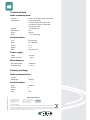
If there’s problem with re-configuration of the IRIS unit it can be reset.
· Disconnect the power supply.
· Open the box
· Set a jumper between the two pins closest to the LED in the 10 pins box header to the right.
· Connect the power supply.
· Disconnect the power and remove the jumper.
· Close the box and connect the power supply.
· The serial port is now set to 9600, 8 bits, 1 stop bit and no parity.
· Send the configuration file to the IRIS using the IRIS configuration program.
Inside the IRIS
Change configuration via radio using another IRIS:
· The IRIS used to relay the configuration must have CRLF
as End of data.
· Add the target IRIS as a lower unit to the IRIS used to
relay the configuration.
· Make sure that relaying IRIS is set to the same radio
channel as the target IRIS.
· Connect the serial cable and power supply to the relaying
IRIS and the power supply to the target IRIS.
· Send the configuration file to the relaying IRIS and it will
be sent to the target IRIS.

© 2004-2010 of Ideus AB
This radio equipment/product satisfies the significant requirements and other relevant stipulations of the “Guideline 1999/5/EG”
This document is copyrighted and all rights are reserved by Ideus AB. This document may not, in whole or in part, be copied, photocopied, or
translated without the prior written consent of Ideus AB. This document contains proprietary information which is not to be used or brought to
knowledge of a third part without the prior written consent of Ideus AB.
RS-232
IRIS-RS232-Short manual-1a
www.irisnetwork.se
TRL-Funksysteme GmbH
Hans-Böckler-Strasse 5a
D-63110 Rodgau-Jügesheim
Germany
Telefon: +49 (0) 6106 / 60 08-0
Telefax: +49 (0) 6106 / 60 08-33
E-Mail: [email protected]
Internet: www.trlfunk.de
Technical data
Radio communication:
Frequency: 433.050 - 434.775 MHz; 439.700 - 439.975 MHz
Channel pattern: 25 kHz channel spacing
70 channels from 433.050 to 434.775 MHz
(12 channels from 439.700 to 439.975 MHz
for the Swedish market)
Sensitivity: -112 dBm @ 50 ohm
Modulation type: FSK
Bit rate: 4800 bit/s
Range: > 1 km (in line of sight)
Serial interface:
Level: EIA-232, RS-232
Speed: 300-115200 Baud
Data bits: 7 or 8
Stop bits: 1 or 2
Parity: Odd, even or none
Power supply:
Voltage: 12-24 VDC
Current consumption: < 100 mA
Miscellaneous:
Size (without antenna): 70x95x30 mm
Temperature range:
0 – +55 °C
Factory settings
Radio communication:
Channel: 1
Message type: Broadcast
Serial interface:
Speed: 9600 Baud
Data bits: 8
Stop bits: 1
Parity: None
-
 1
1
-
 2
2
-
 3
3
-
 4
4


Trl Funksysteme IRIS-RS232 Datasheet
- Type
- Datasheet
- This manual is also suitable for
Ask a question and I''ll find the answer in the document
Finding information in a document is now easier with AI
Other documents
-
 Optiquest iRIS 220 User manual
-
 American Dynamics ControlCenter ADCC0300 User manual
-
IRIS Touch 2 Engineering Manual
-
Bosch DVR-16K User manual
-
Moog Videolarm VLC485 Specification
-
 Lumen Dynamics Group OmniCure S2000 User manual
-
EMS iris+ Installation guide
-
-
-
Bosch Appliances 8555 User manual


