Page is loading ...

The Coolest Thing In Wine Storage
MINI CEILING MOUNT
VERSION 4
OWNER’S MANUAL

Copyright © 2017. WhisperKOOL. All rights reserved.
WhisperKOOL copyrights this manual, the product design, and the design concepts, with all rights reserved. Your rights
with regard to the hardware and manual are subject to the restrictions and limitations imposed by the copyright laws of
the USA. Under copyright laws, this manual may not be copied, reproduced, translated, transmitted, or reduced to any
printed or electronic medium or to any machine-readable form, for any purpose, in whole or in part, without the written
consent of WhisperKOOL.
Every effort has been made to ensure that the information in this manual is accurate. WhisperKOOL is not responsible for
printing or clerical errors.
WhisperKOOL reserves the right to make corrections or improvements to the information provided and to the related
hardware at any time, without notice.
Vinothèque and WhisperKOOL are registered trademarks, and ECE is a trademark of WhisperKOOL. All rights reserved.
Mention of third-party products is for informational purposes only and constitutes neither an endorsement nor a
recommendation. WhisperKOOL assumes no liability with regard to the performance or use of these products.
We manufacture, test and certify 100% of our wine cooling units in
the USA. By sourcing the best components and closely controlling our
manufacturing processes, we can assure the highest-quality,
lowest defect manufacturing rates in the industry.
Conforms to ANSI/UL Std 427
Certied to CAN/CSA Std C22.2 No. 120

TABLE OF CONTENTS
Quick Reference Guide
Knockout Locations ...................................... 7
Display Layout & Specications ........................... 8
Preparing the Wine Cellar ................................... 9
Liquid Thermostat (Bottle Probe) ........................... 12
System Operation. . . . . . . . . . . . . . . . . . . . . . . . . . . . . . . . . . . . . . . . . . . 13
Controller Functions ........................................ 15
WhisperKOOL Troubleshooting Guide ...................... 21
Maintenance Schedule ..................................... 23
Technical Assistance & Accessories ......................... 24
Installation Terms and Conditions .......................... 25
Introduction ................................................ 3
Before You Start ............................................ 4
Receiving & Inspecting the System ......................... 5
Copyright © 2017. WhisperKOOL. All rights reserved.
WhisperKOOL copyrights this manual, the product design, and the design concepts, with all rights reserved. Your rights
with regard to the hardware and manual are subject to the restrictions and limitations imposed by the copyright laws of
the USA. Under copyright laws, this manual may not be copied, reproduced, translated, transmitted, or reduced to any
printed or electronic medium or to any machine-readable form, for any purpose, in whole or in part, without the written
consent of WhisperKOOL.
Every effort has been made to ensure that the information in this manual is accurate. WhisperKOOL is not responsible for
printing or clerical errors.
WhisperKOOL reserves the right to make corrections or improvements to the information provided and to the related
hardware at any time, without notice.
Vinothèque and WhisperKOOL are registered trademarks, and ECE is a trademark of WhisperKOOL. All rights reserved.
Mention of third-party products is for informational purposes only and constitutes neither an endorsement nor a
recommendation. WhisperKOOL assumes no liability with regard to the performance or use of these products.

Page 2 | 1-800-343-9463
MCM 020519
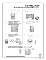
WARNING
The evaporator unit (fan coil unit) must be insulated using the insulation blanket provided in
accordance with this manual. Refer to the insulation blanket installation instructions.
Failure to follow the instructions provided will result in a poor vapor barrier, water
damage, rust, and system corrosion which will void the warranty on your unit.
The evaporator unit (fan coil unit) must be insulated using fiberglass insulation (R19 or
higher) in addition to the provided insulation blanket. This includes the cavity between the
ceiling joists. A warm attic environment will reduce the capacity of the cooling system, as the
system will absorb heat from the attic in addition to the heat load from the wine cellar. This, in
effect, will significantly reduce the cooling system’s ability to cool the wine cellar.
Failure to properly insulate the evaporator unit may cause condensation to form on the
surface of the housing and water damage to the surrounding structure, the cooling unit, and
possibly the wine cellar.
To avoid these issues, install the insulation kit and insulate the surface of the evaporator unit
that is located outside of the wine cellar using fiberglass insulation.
*Additional insulation is required!

www.whisperkool.com | Page 3
Mini Ceiling Mount
WARRANTY REGISTRATION
In order to activate the warranty of your system, the verication and operational
documentation must be completed by the certied refrigeration technician
installing your system and submitted via mail, fax, or e-mail.
Mail to:
WhisperKOOL
ATTN: Warranty Registration
1738 E. Alpine Avenue
Stockton, CA 95205-2505
USA
Fax to:
209-466-4606
Scan and email to:
INTRODUCTION
Customer Service
Thank you for purchasing a WhisperKOOL cooling system. We strive to provide the highest-quality products and the best
possible customer service. If you have any questions about your system, please call us at 1-800-343-9463 or visit
WhisperKOOL.com.
Using the Manual
This manual is intended to assist in the proper maintenance of the cooling system. In order to ensure the longevity of your
cooling unit, the equipment should be installed as outlined in the technician’s manual. It is also vital to establish a proper care
and maintenance schedule. Please read and review this manual carefully and keep it for future reference.
What is the WhisperKOOL Cooling System?
The WhisperKOOL cooling system is a specialized refrigeration system designed for one purpose only: to maintain the optimal
temperature and humidity levels conducive to the proper storage and aging of ne wines. This system produces minimal in-cellar
noise and has the most lenient exhaust requirements. An exterior housing is required for outdoor condensing unit installations.
How Does the Cooling System Work?
Similar to the air conditioning systems used for homes, the evaporator unit and condensing units are installed in separate
locations and are connected by a refrigerant line set. The evaporator portion is commonly installed in the wine cellar, with the
condensing unit is located either outside or in a remote indoor location that is ventilated. An exterior housing is required for
outdoor condensing unit installations.
Temperature Setting
The system is designed to maintain a cellar temperature of 55°F as long as the ambient temperature does not exceed 110°F.

Page 4 | 1-800-343-9463
MCM 020519
BEFORE YOU START
1-800-343-9463
1. Inspect all components prior to installation. If damage is found, please contact your distributor or WhisperKOOL Customer
Service at 1-800-343-9463.
2. The evaporator unit and condensing unit each require a dedicated 115V, 20-amp circuit. Use a surge protector with the unit.
Do not use a GFI (ground fault interrupter) line.
3. The evaporator unit and condensing unit require no communication lines.
4. You are REQUIRED to install a drain line to remove condensation from the evaporator unit.
5. The warranty is not active until a warranty checklist has been received, reviewed, and approved.
6. The system is intended for use in properly designed and constructed wine cellars. Hire a professional wine storage
consultant with a valid contractor’s license to build your wine cellar.
7. WhisperKOOL requires that all split systems be installed by a certified HVAC-R technician only. NATE or equivalent is
recommended.
If you encounter a problem with your WhisperKOOL system, please refer to the Troubleshooting Guide. If you have any further
questions or concerns, or need assistance, please contact WhisperKOOL’s Customer Service at 1-800-343-9463. Please be sure all
testing has been completed prior to contacting Customer Service. Please have your results ready for your representative.

www.whisperkool.com | Page 5
Mini Ceiling Mount
RECEIVING & INSPECTING THE SYSTEM
• Use caution when lifting and check package for damage.
• Lift only at the designated hand-hold locations on the shipping container, or fully support the unit from underneath. A
shipment may include one or more boxes containing accessories.
• Before opening the container, inspect the packaging for any obvious signs of damage or mishandling.
• Write any discrepancy or visual damage on the bill of lading before signing.
• Allow the condensing unit to sit for 24 hours prior to start-up. The condensing unit can be placed in the installation
location, piped and evacuated during this time.
Note: WhisperKOOL units are manufactured in the USA and tested prior to shipment.
• Review the packing slip to verify contents.
• Check the model number to ensure it is correct.
• Check that all factory options ordered are listed.
If any items listed on the packing slip do not match your order information,
contact WhisperKOOL Customer Service immediately.
Check all shipped boxes for the following contents:
Please leave the unit in its original box until you are ready for installation. This will allow you to move the product safely without
damaging it. When you are ready to remove the product from the box, refer to the installation instructions.
TIP: Save your box and all packaging materials. They provide the only safe means of transporting/shipping the unit.
Evaporator Unit Box Condensing Unit Box
(1) Mini Ceiling Mount evaporator unit
(1) Mini Ceiling Mount condensing unit
Evaporator installation hardware bag:
• (12) 2½” Phillips wood screws
• (12) #8 ⁄” Phillips pan-head screws
• (1) Bypass plug
• (1) ¼” barbed coupling
• (2) 3” strip of cork tape
Documentation bag:
• Mini Ceiling Mount Version 2 owner’s manual
• Mini Ceiling Mount Version 2 technician’s
manual
• R-134a split system warranty checklist
KDT Plus hardware bag:
• (1) ⁄” OD grommet
• (2) ½” nylon hole plug
• (4) #6 x 1” Phillips zinc Type A screw
• (4) 8-10 x ⁄” blue plastic screw anchor
Accessory kit bag:
• Stainless steel probe (50 feet)
• KDT Plus display cable (50 feet)
• KDT Plus wall mount bracket assembly
• KDT Plus ush mount bracket assembly
• KDT Plus display assembly
• Flush mount template
• Evaporator installation hardware bag
• KDT Plus hardware bag
Mini Ceiling Mount insulation blanket bag:
• Mini Ceiling Mount insulation blanket
Condensing unit accessory kit:
• (1) Filter drier
• (1) Sight glass
Single-piece mounting bracket

Page 6 | 1-800-343-9463
MCM 020519
QUICK REFERENCE GUIDE
Top View
Bottom View
Note: The unit comes in black. The mounting bracket and front grille
are paintable, enabling you to match your desired color.
Electrical Knockout
Options
Line Set Knockout
Options
Mounting Bracket (Paintable)
Supply and Return Grille (Paintable)
Electrical Knockouts
Line Set
Drain Line
Line Set Knockout

www.whisperkool.com | Page 7
Mini Ceiling Mount
KNOCKOUT LOCATIONS
Side View 1
Side View 3
Side View 2
Side View 4
10.08”
1”
1”
10.08”
11.08”11.08”
7.55”
7.87”
.32”
1.71”
1.71”
1.5”
1.5”
11.08”11.08”
15.67”2”3.5”
.88”
.88”
1.43”
1.43”
9.91” 9.31” 12.74”
9.03”
11.34”
11.34”
22.05”
22.05”
10.08”
1”
Top View
10.34”
1”
11.34”
22.05”
12.74”
1.17”
1.17”
1”

Page 8 | 1-800-343-9463
MCM 020519
MINI CEILING MOUNT SPECIFICATIONS
QUICK REFERENCE GUIDE
Display Layout
Compressor is on
Fan is on
Anti-Frost Cycle
running
Alarm is present
°
F
°
F
View/Change Setpoint
Enter User Menu
Unlock Button
(hold for 1 sec)
Scroll Button
Change Setpoint
55°F
Power On/O
(hold for 5 sec)
Scroll Button
Change Setpoint
Return to Previous
Menu
Model
Mini Evaporator
(Fan Coil Unit)
Mini Condenser
(Air-Cooled Condensing Unit)
Cellar Size Approx. 500 cu. ft. when cellar is fully insulated and sealed with a proper vapor barrier*
BTU/h w/85°F air entering
condenser coil
1730
Dimensions 22.05”L x 11.08”W x 11.34”H 13.97”L x 15.85”W x 9.86”H
Refrigerant R-134a
HP 0.7
Voltage Rating 115V (15-amp dedicated circuit required)
Weight (lbs) 40 38.8
Amps Evaporator: 1 (running amps), compressor: LRA 26, RLA 4.4
Line Set Liquid line ¼”; suction line ⁄” (less than 50 ft.), ½” (more than 50 ft.)
Drain Line ¼” ID clear plastic tubing
Installation
Evaporator unit is installed through the cellar ceiling. Condensing unit can be installed up to 100 line
feet from the evaporator unit.
Thermostat Advanced digital display (50-ft. cable), liquid-temperature-measuring bottle probe (50-ft. cable)
Temp. Delta Can maintain a 55°F cellar temperature with up to 110°F condenser air intake temperature
Warranty Two-year limited warranty (parts and labor)
* Sizing the System to the Room
There are several factors such as glass, stone, and concrete which will change the required amount of BTUs needed to properly cool your wine room.
We strongly recommend utilizing the cellar wizard on the WhisperKOOL website in order to ensure you are selecting the proper cooling system for your
application. Under-sizing your cooling system can lead to premature failure and/or prevent the system from reaching the desired set temperature.

www.whisperkool.com | Page 9
Mini Ceiling Mount
The performance and life of your system is contingent upon the steps you take in preparing the wine cellar. Improp-
erly preparing your enclosure or incorrectly installing your unit may cause unit failure, leaking of condensation, and
other negative side eects.
It is highly recommended that you obtain the assistance of a wine storage professional.
Wine storage professionals work with licensed contractors, refrigeration technicians, and racking companies to build
well-insulated, beautiful, and protective wine cellars. WhisperKOOL has put together some useful tips to assist in the
installation process. Our recommendations are meant to act as a guide in the process of building a proper enclosure.
Your intended location may have specic needs which we do not address.
Wall & Ceiling Framing
Build wine cellar walls using standard 2x4 or 2x6 boards and ceiling joists without violating local or state codes in
your area. As a general rule, the thicker the walls and the higher the insulation value, the more consistent your cellar
temperature will be.
Insulation
Insulation is REQUIRED in order to properly use WhisperKOOL products. It is vital that all walls and ceilings be
insulated to keep the cellar temperature as consistent as possible during the summer and winter months. Standard
berglass or rigid foam insulation is normally used in cellar construction; in some cases, “blown-in” insulation is used.
The R-value, or quality of insulation, is determined by the rate at which heat passes through the insulation. The
higher the R-value, the more resistant the insulation is to conducting heat, and the more consistent your wine cellar’s
temperature will be. Using higher R-values in insulation will lower your operating costs and WhisperKOOL unit run
time. (R-13 is the recommended minimum; R-19 is preferred for interior cellar walls, and R-30 for ceilings and exterior
walls.)
Vapor Barrier
Water vapor creates its own pressure, separate from the ambient air pressure, and will intrude into colder/drier
areas. A vapor barrier is REQUIRED in order to prevent the intrusion of water vapor and maintain the correct cellar
temperature and humidity. It is recommended that 6-millimeter plastic sheeting be applied to the warm side of the
cellar walls. The vapor barrier must also be applied to the outside walls and ceiling. If it is impossible to reach the
outside, then the plastic must be applied from within the cellar. The most common method is to wrap the entire
interior, leaving the plastic loose in the stud cavity so the insulation can be placed between each stud. All of the walls
and ceiling must be wrapped in plastic for a complete vapor barrier.
In areas of high humidity, such as Southern and Gulf States, the vapor barrier will prevent inltration of warm moist
air. The moist air can cause mold to form, and standing water in drain pans promote microbial and fungal growth that
cause unpleasant odors and indoor air quality problems. If mold is found, remove it immediately and sanitize that
portion of the unit.
Note: High humidity signicantly increases the heat load on the cooling system.
Any break in the vapor barriers (cut, nail hole, over-lapping, etc.) will cause a moisture leak and must be sealed. The
electric conduit is a “duct” for vapor to travel in. The conduit should be caulked and sealed on the warm air end.
PREPARING THE WINE CELLAR

Page 10 | 1-800-343-9463
MCM 020519
Unobstructed Airow
Unobstructed airflow to and from the system is critical for the system’s overall performance and lifespan. A
minimum of 3 feet of clearance around the unit is crucial (5 feet is ideal). The air blown by the fans needs to circulate
and either dissipate or absorb heat from the space. The system will operate more efficiently with a greater amount of
air to exchange.
Door and Door Seal
An exterior-grade (1¾”) door must be installed as a cellar door. It is very important that weather stripping is attached
to all four sides of the doorjamb. A bottom “sweep” or threshold is also required. The door must have an excellent
seal to keep the cool cellar air from escaping the cellar. If the door is not sealed properly, the cooling system may run
continuously, shortening its operational lifespan.
In cases where glass doors are used and the room size is close to the recommended system size, the next larger size
WhisperKOOL system should be used. This will compensate for the insulation loss due to the lower insulation rating of
glass.
Note: Avoid attempting to camouflage the unit. This will restrict
airflow, and thus the system’s ability to work efficiently.

www.whisperkool.com | Page 11
Mini Ceiling Mount
Ambient Temperature Factor
The cooling system has the ability to cool a wine cellar eciently to 55°F as long as the ambient temperature of the area
to which it is exhausting does not exceed 110°F. Therefore, the condensing unit should exhaust in a space which will not
exceed 110°F, allowing for proper dissipation of the heat exhausted by the condensing unit. Without proper heat dissipa-
tion the system will not have the capacity to keep the wine at a desirable 55°F.
Ventilation
The necessity of dissipating heat away from the condensing unit is critical to the system’s performance and cannot
be overstated. As the system operates and cools, a greater amount of heat is generated on the condensing side of
the system. Adequate ventilation is required in order to dissipate heat away from the condensing unit. If ventilation
is inadequate, the exhaust will heat the area or room and adversely aect the system’s ability to cool. In some cases, it
may be advisable to install a vent fan to dissipate heat within the exhaust area on the condensing side of the system.
However, you must have a fresh air inlet as well.
WARNING! Allowing your system to operate in high ambient temperatures for
extended periods of time will greatly decrease the life of your system and void
your warranty. The cooler the temperature of the air entering the condenser coil,
the more cooling capacity the system has. The less heat gain through the common
wall, the lower the consumption of electricity.
Note: The unit comes in black. The mounting bracket and front grille
are paintable, enabling you to match your desired color.
CEILING
EVAPORATOR
UNIT
Note: If you are unsure whether you have adequate ventilation in your installation location, please
contact us to assess your specic installation at [email protected] or 1-800-343-9463.

Page 12 | 1-800-343-9463
MCM 020519
LIQUIDMEASURING THERMOSTAT SYSTEM BOTTLE PROBE
WhisperKOOL cooling units come with a liquid-temperature-measuring thermostat. The self-calibrating probe con-
tains a sensor chip, which communicates back and forth with the thermostat. This results in a consistent temperature
setting and accuracy. Wine should be kept at a very precise, controlled temperature and humidity. By measuring the
liquid temperature rather than air, the unit will operate 75–80% of the time.
Setting up the Bottle Probe:
1. Locate an empty wine bottle.
2. Fill it 75% full with room-temperature tap water.
3. Place bottle probe securely into bottle as seen in Figure 1.
4. Place bottle off to the side of the unit in your wine cellar, with the probe level.
5. To ensure a consistent temperature, place bottle probe approximately three
(3) feet away from the air output and not in the flow of the air.
It is recommended that the bottle be placed in a central location of your
wine cellar. Avoid pulling too much on the probe cord. It may become
disconnected resulting in limited functionality of the unit.
Note: The thermostat can be set between 50–70°F.
Remember: The unit operates based on the temperature of the water.
Do not be misled by thermostats reading air temperature. The air temperature
in the cellar will be cooler than the liquid temperature of the wine while it is
reaching the optimum balanced temperature.
Figure 1

www.whisperkool.com | Page 13
Mini Ceiling Mount
SYSTEM OPERATION
Initial Start-Up
When the unit is plugged in and power is sent to the
controller, a beep will sound, conrming that the controller is
getting power. All LEDs on the display will blink three times.
Three dashes will then appear on the screen. All display LEDs will
then blink three times. Once the controller has gone through
the initial startup process, and all LEDs have cycled, the home
screen will be displayed.
Setpoint
The setpoint is preset at the factory to 55°F. It can be adjusted by
the customer between 50–70°F in one-degree increments.
Indoor Fan Operation
The indoor fan will run when the controller is calling for cooling
and turn o once the cooling cycle has ended. During the
cooling cycle, the system will remove some relative humidity
from the cellar. Some of the humidity that was removed can be
reintroduced into the cellar by adjusting the “fan on” and “fan o”
functions. (The cooling system is not equipped with a humidier
and does not add humidity.)
The FOF cycle should be shortened rst. This will reduce the
amount of time that the fan remains o following a cooling cycle.
When the unit has completed a cooling cycle, the compressor
and the condenser fan will turn o, but the indoor fan will
continue to run for whatever length of time the customer has
set. The Fon function may then be lengthened to allow the fan
to run longer and reintroduce moisture from the evaporator coil
back into the wine cellar.
For more information about fan settings, refer to the User Menu
on page 18.
Anti-Short Cycle
The Anti-Short Cycle ensures that the unit will remain o for a
period of ve minutes after the unit has reached the setpoint.
This allows the pressure in the refrigeration system to equalize
prior to starting the compressor.
Once the solenoid relay is de-energized, the controller must
wait ve minutes before reenergizing the relay. This prevents
the compressor from repeatedly turning o and on. If the unit
is calling for cooling during this time, the compressor icon will
blink, indicating that cooling is needed but the controller is
waiting for the Anti-Short Cycle delay.
Anti-Frost Cycle
When the evaporator probe senses a temperature of 26°F for
a duration of one minute, an Anti-Frost Cycle will be initiated.
This will shut down the compressor, allowing the evaporator fan
to run and melt any frost accumulation on the coil. While the
Anti-Frost Cycle is running, “dEF” will be displayed on the screen.
The compressor will remain o until the evaporator coil reaches
40°F, or for a maximum of one hour. The unit will then return to
normal operation.
Operation in Low Ambient Temperatures
The condensing unit comes equipped with a LAC (Low Ambient
Control). The LAC is a three-way modulating valve that responds
to discharge pressure. When the discharge pressure falls below
the valve’s dome pressure, the valve modulates open to the
discharge port which allows discharge gas to bypass the
condenser. Mixing the discharge gas with the liquid creates high
pressure at the condenser outlet, reducing the ow and causing
liquid to backup in the condenser. Flooding the condenser
reduces the area available for condensing. This reduction in
condenser surface area results in a rise in condensing pressure
during cold ambient conditions.
The condensing unit controller is preset at the factory. The cut-
in pressure is preset to 25psi and the cut-out pressure at 15psi.
During low ambient temperatures (40°F or below), it will be
necessary to adjust the cut-in pressure to 10-15psi (15psi is
preferred) and the cut-out to 5psi to ensure compressor startup.
See page 19 for instructions on adjusting the cut-in and cut-out
pressures of the condensing unit.
Digital Display
The display is designed to give the user the ability to adjust
the setpoint, Fon/FOF parameters, and other settings. (See
User Menu on page 18 for more details.) The bottle probe
temperature is displayed by default. “dEF” will be displayed
during an Anti-Frost Cycle. The bottle probe and evaporator
probe temperatures can be accessed by pushing the SET button
and scrolling through “Pb1” (bottle probe) and “Pb2” (evaporator
probe). The light button may be used as an unlock button.
Safety Features
In the event of a faulty bottle probe, the compressor will cycle
o for 10 minutes and on for 40 minutes. “E1” will be displayed
on the screen.
Alarms
See “Alarm Codes” in the Controller Functions chart.

Page 14 | 1-800-343-9463
MCM 020519
Compressor is on
Fan is on
Anti-Frost Cycle running
Alarm is present
°
F
°
F
View/Change Setpoint
Enter User Menu
(hold for 3 sec)
Unlock Button
(hold for 1 sec)
Scroll Button
Change Setpoint
55°F
Power On/O
Scroll Button
Change Setpoint
Return to Previous
Menu
DISPLAY LAYOUT

www.whisperkool.com | Page 15
Mini Ceiling Mount
Button Normal Functions
INITIAL STARTUP
When the unit is plugged in and power is sent to the controller, a beep will sound, conrming
that the controller is getting power. All LEDs on the display will blink three times. Three dashes
will then appear on the screen. All display LEDs will then blink three times. Once the controller
has gone through the initial startup process, and all LEDs have cycled, the home screen will be
displayed.
UNLOCKING THE
DISPLAY
Press and hold any button for one second to unlock the display. (A white LED will appear in the
top left corner of the button being pressed.) A beep will sound, signifying that the
display is unlocked. NOTE: The display must be unlocked before any button functions become
available.
ON/OFF
To turn the unit ON, press and hold the ON/OFF button until the red LED turns OFF.
To turn the unit OFF, press and hold the ON/OFF button until the red LED turns ON.
UP/DOWN
The up and down arrows are used to navigate through menus and adjust parameters such as
setpoint, Fon/FOF, etc.
SET
• To change the setpoint, press the SET button. When “SEt” is displayed on the screen, press
the SET button once more. Use the UP and DOWN ARROW buttons in order to change the
value until the desired setpoint is reached.
• The SET button allows you to view the setpoint, evaporator temperature, bottle tempera-
ture, alarms, and the hidden menu.
• Press the SET button once. “SEt” will be displayed. Press the UP or DOWN ARROW buttons
to scroll through ALr, Pb1, or Pb2.
Set Setpoint
Alr Alarm folder
Pb1 Liquid (bottle probe) temperature
Pb2 Evaporator coil temperature
• Press the SET button again to view any of these values.
• Hold the SET button for approximately 5 seconds to enter the User Menu. (More informa-
tion about the User Menu is available on page 18.)
• Other parameters in the User Menu which are not available for adjustment include: idF,
rEL, and LAn.
ESC
This button conrms changes made to parameters such as the setpoint and returns you to the
previous menu.
LIGHT
The light function is not in use. However, this button can still be used to unlock the display.
55°F
55°F
55°F
55°F
55°F
55°F
CONTROLLER FUNCTIONS

Page 16 | 1-800-343-9463
MCM 020519
Icon Meaning
SNOWFLAKE
Blinking: The unit is calling for cooling, but must wait ve minutes before restarting the com-
pressor. This ve-minute delay serves as an Anti-Short Cycle for the compressor’s
protection.
Constant: The unit is in cooling mode and the condensing unit is running.
DRIPPING SNOWFLAKE
The unit is undergoing an Anti-Frost Cycle. While the Anti-Frost Cycle is running, “dEF” will be
displayed on the screen. See System Operation page for further details.
FAN
The evaporator fan is running.
ALARM
The alarm icon is shown when the unit encounters an issue that needs attention. Alarm codes
are explained on the following page. All temperature-related alarms are blocked for the rst
10 hours after the unit is plugged in to allow the system to stabilize and acclimate to the new
environment.
ICON GLOSSARY

www.whisperkool.com | Page 17
Mini Ceiling Mount
Code Cause Solution
The following alarm codes will be displayed on the screen along with the alarm icon.
E1
Bottle probe is not connected Attach bottle probe to circular connector
Faulty bottle probe connection Locate faulty bottle probe connection by inspecting all wiring connections
between the bottle probe and the circuit board. The two-pin connector for the
bottle probe should be connected to the CPB/PB1 terminal on the circuit board.
If it is not connected, plug it in. If a faulty connection has been identied, correct
the issue or contact customer service for further assistance.
NOTE: The E1 code will not appear in the alarms menu. It will be permanently
displayed on the screen.
Defective bottle probe Replace the bottle probe
E2
Faulty evaporator probe
connection
Locate faulty evaporator probe connection by inspecting evaporator probe wire.
The two-pin connector for the evaporator probe should be connected to the
CPB/PB2 terminal on the circuit board. If it is not connected, plug it in.
Defective evaporator probe Replace the evaporator probe
E7
No communication between
keypad and circuit board for 60
seconds
Verify that the display cable is connected to the keypad and the circuit board and
is not damaged, frayed, or kinked. If problem persists, contact Customer Service
for troubleshooting information.
E10
Clock battery is dead Replace battery
NOTE: A dead clock battery will not aect the operation of your cooling unit.
The following alarm codes will not be displayed on the home screen. However, the alarm icon
will be displayed in the event of an alarm. The alarms can be viewed in the Set Menu’s ALr folder.
EA
Unit is not draining properly 1. Check to see that the unit is level; if not, level it
2. Verify that the drain line is not clogged; if so, clear obstruction
3. Ensure that the condensate pump is operating
4. Verify wire connection at D.I. port of circuit board
NOTE: If the drain line is obstructed or the pump fails for some reason, and the
water level in the drip tray gets too high, the unit will not operate until the water
in the internal drip tray drops back below the proper level.
AH1
The bottle probe is sensing a
temperature that is 4°F above the
setpoint
1. Allow time for the wine to reach the desired temperature
2. Ensure that the cellar is sealed properly
3. Verify that the bottle probe is calibrated correctly (refer to the User Menu on
the following page)
4. Verify that the unit is sized correctly for the cellar
AL1
The bottle probe is sensing a
temperature that is 4°F below the
setpoint
1. Make sure the unit is not in cooling mode (the snowake icon will not be
illuminated)
2. Add heat to the room until the wine reaches the desired temp
3. Verify that the bottle probe is calibrated correctly (refer to the User Menu on
the following page)
Ad2
The Anti-Frost Cycle ended on
time-out
1. Check the evaporator coil for ice buildup. Unplug the unit and allow the coil to
thaw before restarting.
2. Make sure the room to which the unit is exhausting is not below 60°F
3. If the unit repeatedly goes into Anti-Frost Cycles (one per minute), call
Customer Service for more troubleshooting information
ALARM CODES

Page 18 | 1-800-343-9463
MCM 020519
The User Menu is accessed by pressing and holding the SET button for 3 seconds. Use the UP and DOWN ARROW
buttons to navigate to desired parameters. Press the SET button again to view these parameters. Press the UP and
DOWN ARROW buttons to adjust a parameter.
The following parameters are available in the menu:
Parameter Description
Fdc - humidity enhancement This parameter is measured in minutes, and is preset at the
factory to 1. An increase in this parameter will increase the humidity
enhancement of your cellar. This parameter should not be adjusted
to zero. Adjustments should be made in increments of 5, with a
maximum of 15 and a minimum of 1. After making any adjustments
to humidity enhancement, you should wait a minimum of 3 days
before making any additional adjustments. This will allow sucient
time for the cellar to acclimate to the new setting.
FOF - “fan o” This setting controls how long the fan stays o after the setpoint
has been reached. It is preset to 15 minutes. This setting should
not be adjusted, as most properly constructed wine cellars retain
an ample amount of humidity during the “fan o” cycle. If, however,
you wish to decrease the duration of the “fan o” cycle (in order to
increase the wine cellar’s relative humidity), you can adjust this
setting in the User Menu.
Fon - “fan on” The “fan on” time is preset to zero minutes. This keeps the relative
humidity of the wine cellar at a stable level. If, however, you wish
to raise the relative humidity of your wine cellar, you can increase
the duration of the “fan on” cycle in increments of ve (5, 10, or 15
minutes). After making any adjustment to the “fan on” cycle, you
should wait a minimum of 3 days before making any additional
adjustments. This will allow sucient time for the cellar to acclimate
to the new setting.
CA1 - bottle probe (Pb1) calibration CA1 - bottle probe (Pb1) calibration: You may use this parameter
to calibrate the bottle probe to a known temperature. This param-
eter can be adjusted between -12°F and 12°F. For example, if the
bottle probe temperature is 58°F, and the known temperature is
55°F, you can set the CA1 parameter to -3°F to match the known
temperature.
PA2 - installer menu This menu is only accessible using a password and is not available
for adjustment.
dOA - digital input This setting determines which of the unit’s components will be
activated or deactivated when a certain electrical relay is activated
or deactivated in response to an alarm. The controller comes pre-
programmed with a factory setting of 2.
2 = activates the compressor and fans
5 = disables the compressor and fans
NOTE: Setting the dOA to any number other than 2 or 5 will prevent
the unit from operating properly.
USER MENU
/