Pro-Form LE TOUR DE FRANCE PFEX09916.1 User manual
- Type
- User manual

USER’S MANUAL
CAUTION
Read all precautions and
instructions in this manual before
using this equipment. Keep this
manual for future reference.
Model No. PFEX09916.1
Serial No.
Write the serial number in the space
above for reference.
proform.com
Serial Number
Decal
To register your product and
activate your warranty today,
go to my.proform.com.
For service at any time, go to
proformservice.com.
Or call 1-877-660-1168
Mon.–Fri. 6 a.m.–6 p.m. MT
Sat. 8 a.m.–12 p.m. MT
Please do not contact the store.
ACTIVATE YOUR
WARRANTY
CUSTOMER CARE

2
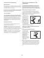
This drawing shows the location(s) of the
warning decal(s). If a decal is missing
or illegible, see the front cover of this
manual and request a free replacement
decal. Apply the decal in the location
shown. Note: The decal(s) may not be
shown at actual size.
WARNING DECAL PLACEMENT . . . . . . . . . . . . . . . . . . . . . . . . . . . . . . . . . . . . . . . . . . . . . . . . . . . . . . . . . . . . . . .2
IMPORTANT PRECAUTIONS ..................................................................3
BEFORE YOU BEGIN. . . . . . . . . . . . . . . . . . . . . . . . . . . . . . . . . . . . . . . . . . . . . . . . . . . . . . . . . . . . . . . . . . . . . . . .5
PART IDENTIFICATION CHART. . . . . . . . . . . . . . . . . . . . . . . . . . . . . . . . . . . . . . . . . . . . . . . . . . . . . . . . . . . . . . . .6
ASSEMBLY . . . . . . . . . . . . . . . . . . . . . . . . . . . . . . . . . . . . . . . . . . . . . . . . . . . . . . . . . . . . . . . . . . . . . . . . . . . . . . . .7
HOW TO USE THE TRAINING BIKE ...........................................................13
FCC INFORMATION . . . . . . . . . . . . . . . . . . . . . . . . . . . . . . . . . . . . . . . . . . . . . . . . . . . . . . . . . . . . . . . . . . . . . . . .25
MAINTENANCE AND TROUBLESHOOTING .....................................................26
EXERCISE GUIDELINES ....................................................................27
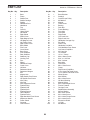
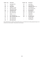
PART LIST. . . . . . . . . . . . . . . . . . . . . . . . . . . . . . . . . . . . . . . . . . . . . . . . . . . . . . . . . . . . . . . . . . . . . . . . . . . . . . . .29
EXPLODED DRAWING. . . . . . . . . . . . . . . . . . . . . . . . . . . . . . . . . . . . . . . . . . . . . . . . . . . . . . . . . . . . . . . . . . . . . .31
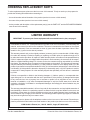
ORDERING REPLACEMENT PARTS. . . . . . . . . . . . . . . . . . . . . . . . . . . . . . . . . . . . . . . . . . . . . . . . . . . Back Cover
LIMITED WARRANTY. . . . . . . . . . . . . . . . . . . . . . . . . . . . . . . . . . . . . . . . . . . . . . . . . . . . . . . . . . . . . . . Back Cover
WARNING DECAL PLACEMENT
TABLE OF CONTENTS
PROFORM and IFIT are registered trademarks of ICON Health & Fitness, Inc. LE TOUR DE FRANCE is a regis-
tered trademark of Société du Tour de France. App Store is a trademark of Apple Inc., registered in the U.S. and
other countries. Android and Google Play are trademarks of Google Inc. The BLUETOOTH
®
word mark and logos
are registered trademarks of Bluetooth SIG, Inc. and are used under license. IOS is a trademark or registered
trademark of Cisco in the U.S. and other countries and is used under license.

3
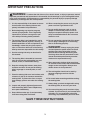
IMPORTANT PRECAUTIONS
WARNING: To reduce the risk of burns, fire, electric shock, or injury to persons, read all
important precautions and instructions in this manual and all warnings on your training bike before
using your training bike. ICON assumes no responsibility for personal injury or property damage
sustained by or through the use of this product.
1. It is the responsibility of the owner to ensure
that all users of the training bike are ade-
quately informed of all precautions.
2. Before beginning any exercise program,
consult your physician. This is especially
important for persons over age 35 or per-
sons with pre-existing health problems.
3. The training bike is not intended for use by
persons with reduced physical, sensory, or
mental capabilities or lack of experience and
knowledge, unless they are given supervi-
sion or instruction about use of the training
bike by someone responsible for their safety.
4. Use the training bike only as described in
this manual.
5. The training bike is intended for home use
only. Do not use the training bike in a com-
mercial, rental, or institutional setting.
6. Keep the training bike indoors, away from
moisture and dust. Do not put the training
bike in a garage or covered patio, or near
water.
7. Place the training bike on a level surface with
at least 2 ft. (0.6 m) of clearance around the
training bike. To protect the floor or carpet
from damage, place a mat under the training
bike.
8. Inspect and properly tighten all parts each
time the training bike is used. Replace any
worn parts immediately.
9. Keep children under age 13 and pets away
from the training bike at all times.
10. When connecting the power cord, plug the
power cord into a grounded circuit.
11. Do not modify the power cord or use an
adapter to connect the power cord to an
improper receptacle. Keep the power cord
away from heated surfaces. Do not use an
extension cord.
12. Do not operate the training bike if the power
cord or plug is damaged, or if the training
bike is not working properly.
13. DANGER: Always unplug the power
cord and press the power switch to the off
position when the training bike is not in
use and before cleaning the training bike.
Servicing other than the procedures in this
manual should be performed by an autho-
rized service representative only.
14. Wear appropriate clothes while exercising;
do not wear loose clothes that could become
caught on the training bike. Always wear
athletic shoes for foot protection.
15. The training bike should not be used by
persons weighing more than 350 lbs.
(159 kg).
16. Be careful when mounting and dismounting
the training bike.
17. Always keep your back straight while using
the training bike; do not arch your back.
18. Over exercising may result in serious injury
or death. If you feel faint, if you become short
of breath, or if you experience pain while
exercising, stop immediately and cool down.
SAVE THESE INSTRUCTIONS

4
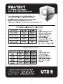
all
STANDARD SERVICE PLANS

5
Congratulations for selecting the revolutionary
PROFORM
®
LE TOUR DE FRANCE
®
training bike.
The LE TOUR DE FRANCE training bike is unlike any
ordinary exercise bike. With full adjustability, a Wi-Fi
®
cycling console, an incline system that simulates actual
road terrain, and an array of other innovative features,
the LE TOUR DE FRANCE training bike is designed to
let you enjoy the outdoor cycling experience indoors.
For your benefit, read this manual carefully before
you use the training bike. If you have questions after
reading this manual, please see the front cover of this
manual. To help us assist you, note the product model
number and serial number before contacting us. The
model number and the location of the serial number
decal are shown on the front cover of this manual.
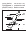
Before reading further, please familiarize yourself with
the parts that are labeled in the drawing below.
Saddle
Resistance
Control
Saddle Carriage
Incline Control
Adjustment Handle
Adjustment Handle
Handlebar
Water Bottle Holder*
Hand Weight
Tray
Adjustment Handle
Wheel
Pedal/Strap
Console
Leveling Foot
Power Switch
*Water bottle is not included
Length: 5 ft. 5 in. (165 cm)
Width: 2 ft. 1 in. (64 cm)
BEFORE YOU BEGIN

6
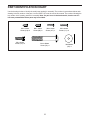
M10 x 58mm
Screw (74)–4
M4 Washer
(54)–1
M6 x 16mm
Screw (110)–4
M4 x 10mm
Screw (116)–4
M4 x 14mm
Screw (117)–1
M4 x 12mm
Screw (95)–2
M4 x 16mm
Screw (111)–4
PART IDENTIFICATION CHART
Use the drawings below to identify the small parts needed for assembly. The number in parentheses below each
drawing is the key number of the part, from the PART LIST near the end of this manual. The number following the
key number is the quantity needed for assembly. Note: If a part is not in the hardware kit, check to see if it
has been preassembled. Extra parts may be included.

7
2
22
74
A
1
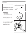
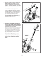
2. Remove and discard the indicated shipping
insert (A). If there are shipping screws in the
Front Stabilizer (22), remove and discard
them.
Attach the Front Stabilizer (22) to the Base (1)
with two M10 x 58mm Screws (74).
ASSEMBLY
• To hire an authorized service technician to
assemble the training bike, call 1-800-445-2480.
• Assembly requires two persons.
• Place all parts in a cleared area and remove the
packing materials. Do not dispose of the packing
materials until you nish all assembly steps.
• Left parts are marked “L” or “Left” and right parts
are marked “R” or “Right.”
• To identify small parts, see page 6.
• In addition to the included tool(s), assembly
requires the following tools:
one Phillips screwdriver
Assembly may be easier if you have your own set
of wrenches. To avoid damaging parts, do not use
power tools.
1. Go to my.proform.com on your computer and
register your product.
• activates your warranty
• saves you time if you ever need to contact
Customer Care
• allows us to notify you of upgrades and offers
Note: If you do not have internet access, call
Customer Care (see the front cover of this
manual) and register your product.
1

8
2
3
B
47
3
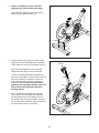
3. If there are shipping screws in the Rear
Stabilizer (23), remove and discard them.
Attach the Rear Stabilizer (23) to the Base (1)
with two M10 x 58mm Screws (74).
74
23
1
4. Using a plastic bag to keep your fingers clean,
apply some of the included grease to the sides
of the channel on the top of the Saddle Post (3).
Next, orient the Saddle Post (3) so that the
height indicators (B) are on the side shown.
Loosen the indicated Adjustment Handle (47),
and insert the Saddle Post (3) into the Frame (2).
Move the Saddle Post upward or downward
to the desired position, and then tighten the
Adjustment Handle. When you are finished
tightening the Adjustment Handle, make sure
that the end of the Adjustment Handle is
pointing upward.
Note: The Adjustment Handle (47) functions
like a ratchet. Turn the Adjustment Handle in
the desired direction, pull it outward, turn it in
the opposite direction, push it inward, and then
turn it in the desired direction again. Repeat this
process as many times as necessary.
4
Grease

9
5
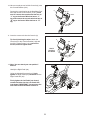
5. Note: You can attach your own saddle to the
Saddle Carriage (4) if desired. Loosen the
attachment hardware (not shown) beneath the
Saddle (5), and remove the Saddle. Then, attach
your own saddle and retighten the attachment
hardware.
Orient the Saddle Carriage (4) as shown.
Loosen the Adjustment Handle (47), and slide
the Saddle Carriage (4) into the Saddle Post (3).
Slide the Saddle Carriage to the desired posi-
tion, and tighten the Adjustment Handle.
Then, attach an M4 Washer (54) and the
Carriage Cover (91) to the Saddle Carriage (4)
with an M4 x 14mm Screw (117).
3
4
5
117
47
54
91
6
6
2
C
105
68
47
130
6. See step 8. If the Handlebar Clamp (28) and
four M6 x 16mm Screws (110) are preattached
to the Handlebar Carriage (105), remove them
and set them aside until step 8.
While a second person holds the Handlebar Post
(6) near the Frame (2), connect the Handlebar
Post Wire (68) to the Frame Wire (130). Then,
untie and discard the wire tie (C) on the Frame
Wire. Insert the excess wire into the Frame.
Tip: Avoid pinching the wires. Loosen the
indicated Adjustment Handle (47), and insert
the Handlebar Post (6) into the Frame (2). Move
the Handlebar Post upward or downward to the
desired position, and tighten the Adjustment
Handle.
Avoid pinching
the wires

10
9
131
132
95
81
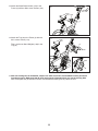
9. Identify the Right Control (131), which is marked
“Resistance.” Connect the wire on the Right
Control to the Right Control Wire (81). Insert the
excess wire into the Handlebar (7).
Tip: Avoid pinching the wires. Attach the Right
Control (131) with an M4 x 12mm Screw (95).
Repeat this step for the Left Control (132).
7. Have a second person hold the Handlebar (7)
near the Handlebar Carriage (105).
Locate the wire tie (D) in the right side of the
Handlebar (7). Tie the indicated end of the
wire tie to the Right Control Wire (81), which is
marked with a tag. Then, pull the other end of
the wire tie until the Right Control Wire is routed
through the Handlebar. Then, untie and discard
the wire tie.
Route the Left Control Wire (70) through the
Handlebar (7) in the same way.
8. Tip: Avoid pinching the wires. Hold the
Handlebar (7) on the Handlebar Carriage (105),
and rotate the Handlebar to the desired angle;
make sure that the Handlebar is centered on
the Handlebar Carriage.
Attach the Handlebar (7) with the Handlebar
Clamp (28) and four M6 x 16mm Screws (110);
start all the Screws, and then tighten them.
7
8
7
7
110
70
7
81
D
D
28
105
Avoid pinching
the wires
105
Avoid pinching
the wires
D
81
7

11
10
111
124
124
81
68
70
9
9
10. Have a second person hold the Console (9) near
the Console Bracket (124).
Connect the console wires to the Handlebar Post
Wire (68) and the Control Wires (70, 81); make
sure to connect the console wire that has an
“L” tag to the Control Wire that has an “L”
tag, and connect the console wire that has an
“R” tag to the Control Wire that has an “R”
tag.
11. Insert the excess wire into the Console (9).
Tip: Avoid pinching the wires. Attach the
Console (9) to the Console Bracket (124) with
four M4 x 16mm Screws (111); start all the
Screws, and then tighten them.
11
12
12. Note: You can attach your own pedals if
desired.
Identify the Right Pedal (62).
Using the included flat wrench tool, firmly
tighten the Right Pedal (62) clockwise into the
Right Crank Arm (64).
Firmly tighten the Left Pedal (not shown)
counterclockwise into the Left Crank Arm
(not shown). IMPORTANT: You must turn the
Left Pedal counterclockwise to attach it.
62
64
Avoid
pinching
the wires

12
129
13. Attach the Water Bottle Holder (129) to the
Frame (2) with two M4 x 10mm Screws (116).
13
8
8
116
128
15. After the training bike is assembled, inspect it to make sure that it is assembled correctly and that it
functions properly. Make sure that all parts are properly tightened before you use the training bike.
Note: Extra parts may be included. Place a mat beneath the training bike to protect the floor.
14. Attach the Tray (8) to the Frame (2) with two
M4 x 10mm Screws (116).
Then, set the two Hand Weights (128) in the
Tray (8).
14
2
2
116

13
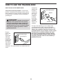
HOW TO PLUG IN THE POWER CORD
This product must be grounded. If it should mal-
function or break down, grounding provides a path of
least resistance for electric current to reduce the risk
of electric shock. The power cord has a plug with a
grounding pin.
Plug the
power cord
into an
appropriate
outlet that
is properly
installed and
grounded in
accordance
with all local
codes and
ordinances. The outlet must be on a nominal 120-volt
circuit.
A temporary
adapter may
be used to
connect the
power cord
to a 2-pole
receptacle
as shown
at the right
if a properly
grounded
outlet is not
available.
The lug or wire extending from the adapter must
be connected with a metal screw to a permanent
ground such as a properly grounded outlet box cover.
Some 2-pole receptacle outlet box covers are not
grounded. Before using an adapter, contact a quali-
fied electrician to determine whether the outlet
box cover is grounded before using an adapter.
The temporary adapter should be used only until
a properly grounded outlet can be installed by a
qualified electrician.
HOW TO USE THE TRAINING BIKE
DANGER: Improper connection of
the power cord increases the risk of electric
shock. Do not modify the plug; if it will not fit
an outlet, have a proper outlet installed by a
qualified electrician. If you are unsure whether
the product is properly grounded, contact a
qualified electrician.
Grounded Outlet
2-pole Receptacle
Grounding Pin
Adapter
Lug
Metal Screw

14
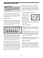
FEATURES OF THE TRAINING BIKE
Measuring Watts
Each training bike is individually calibrated to measure
your power output and allow you to monitor your watts
and RPMs directly on the console.
By monitoring your watts and RPMs, you can see how
hard you are training and make sure that you are chal-
lenging yourself and improving.
The Incline System
The training bike can incline and decline up to 15 per-
cent to realistically simulate outdoor terrain. When you
create maps of your actual training routes on iFit.com
(see the console instructions beginning on page 17
for more information), the training bike will automati-
cally incline and decline to match the terrain of your
training routes.
Pedaling Form Features
The training bike has multiple features to help you
develop correct pedaling form:
Freewheel—The training bike has a freewheel that
simulates a road bike rather than a fixed-drive spin
bike. This discourages you from letting your feet coast
through the top and bottom of your pedal stroke.
Flywheel—The flywheel on the training bike has the
correct inertia to allow you to pedal smoothly while
encouraging you to use good pedaling form.
HOW TO ADJUST THE GEOMETRY OF THE
TRAINING BIKE
The training bike can be adjusted to promote correct
form and to ensure proper training of the muscles.
Note: Make adjustments in small increments, and
then pedal the training bike to test the adjustments.
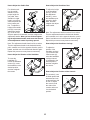
How to Adjust the Angle of the Saddle
You can adjust the angle of the saddle to the posi-
tion that is most comfortable. You can also adjust the
saddle forward or backward for increased comfort or to
adjust the distance to the handlebar.
To adjust the sad-
dle, first loosen the
attachment hard-
ware (A) beneath
the saddle a few
turns. Next, tilt the
saddle upward or
downward or slide
the saddle forward
or backward. Then,
retighten the attachment hardware.
Note: You can remove the saddle and attach your
own saddle if desired.
How to Adjust the Saddle Carriage
To adjust the posi-
tion of the saddle
carriage (B), loosen
the adjustment
handle (C), move
the saddle car-
riage forward or
backward, and then
retighten the adjust-
ment handle.
Note: The adjustment handle functions like a ratchet.
Turn the adjustment handle in the desired direction,
pull it outward, turn it in the opposite direction, push it
inward, and then turn it in the desired direction again.
Repeat this process as many times as necessary.
A
B
C

15
How to Adjust the Saddle Post
For effective train-
ing, the saddle
should be at the
proper height. As
you pedal, there
should be a slight
bend in your knees
when the pedals are
in the lowest posi-
tion. To adjust the
height of the saddle
post (D), loosen the
adjustment handle
(E), move the sad-
dle post upward or downward, and then retighten the
adjustment handle. When you are finished tighten-
ing the adjustment handle, make sure that the end
of the adjustment handle is pointing upward.
Note: The adjustment handle functions like a ratchet.
Turn the adjustment handle in the desired direction,
pull it outward, turn it in the opposite direction, push it
inward, and then turn it in the desired direction again.
Repeat this process as many times as necessary.
How to Adjust the Rotation of the Handlebar
To rotate the
handlebar (F),
loosen the indicated
screws (G), rotate
the handlebar to the
desired position,
and then retighten
the screws.
How to Adjust the Handlebar Post
To adjust the height
of the handlebar
post (H), loosen
the adjustment
handle (I), move
the handlebar post
upward or down-
ward, and then
retighten the adjust-
ment handle.
Note: The adjustment handle functions like a ratchet.
Turn the adjustment handle in the desired direction,
pull it outward, turn it in the opposite direction, push it
inward, and then turn it in the desired direction again.
Repeat this process as many times as necessary.
How to Adjust the Handlebar Carriage
To adjust the
position of the
handlebar carriage
(J), loosen the indi-
cated screws (K),
move the handlebar
carriage forward
or backward to the
desired position,
and then retighten
the screws.
How to Adjust the Position of the Console
The console (L) can
be tilted upward and
downward and can
be pivoted from side
to side. To adjust
the console, hold
the sides of the
console and move
it to the desired
position.
E
D
G
F
I
H
K
J
L

16
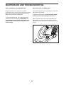
HOW TO LEVEL THE TRAINING BIKE
If the training bike
rocks slightly on
your floor during
use, turn one or
both of the leveling
feet (M) on the rear
stabilizer until the
rocking motion is
eliminated.
HOW TO USE THE PEDALS
To use the pedals
(O), insert your
shoes into the toe
cages and pull the
ends of the toe
straps. To adjust the
toe straps, press
and hold the tabs
on the buckles,
adjust the toe straps
to the desired
position, and then
release the tabs.
Note: You can attach your own pedals to the training
bike if desired.
HOW TO USE THE HAND WEIGHTS
To add strength-
training exercise to
your workouts, use
the hand weights
(O). You can alter-
nate performing
pedaling exercise
on the training bike
with performing
strength-training
exercise next to the training bike. You can also pivot
the console sideways so that you can view the screen
while you are performing strength-training exercises.
When you are not using the hand weights, store them
on the hand weight tray.
M
M
N
O

17
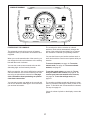
Iceman
EBPF01215V1
PFEX01215
CONSOLE DIAGRAM
FEATURES OF THE CONSOLE
The advanced console offers an array of features
designed to make your workouts more effective and
enjoyable.
When you use the manual mode of the console, you
can change the incline and resistance of the training
bike with the touch of a button.
You can also create custom manual workouts with
alternating high- and low-intensity intervals.
While you exercise, the console will display continuous
exercise feedback. You can also measure your heart
rate using an optional heart rate monitor. See page
22 for information about purchasing an optional
chest heart rate monitor.
You can even connect your tablet to the console and
use the iFit
®
Bluetooth Tablet app to record and track
your workout information.
The console also offers a selection of onboard
workouts. Each workout automatically changes the
incline of the training bike and allows you to change
the resistance to maintain your pedaling cadence.
You can also listen to your favorite workout music or
audio books with the console sound system while you
exercise.
To turn on the power, see page 18. To use the
manual mode, see page 18. To use an onboard
workout, see page 21.
To use the sound system, see page 22. To con-
nect your tablet to the console, see page 23. To
connect your heart rate monitor to the console,
see page 23. To use the settings mode, see
page 24.
The console can display speed and distance in either
miles or kilometers and weight in either pounds or kilo-
grams. To nd which unit of measurement is selected,
see step 3 on page 24.
If there is a sheet of plastic on the display, remove the
plastic.

18
HOW TO TURN ON THE POWER
IMPORTANT: If the training bike has been exposed
to cold temperatures, allow it to warm to room tem-
perature before you turn on the power. If you do
not do this, you may damage the console displays
or other electrical components.
Plug in the power cord (see
HOW TO PLUG IN THE
POWER CORD on page
13). Next, locate the
power switch on the frame
near the power cord. Press
the power switch to the
reset position.
The display will then turn on and the console will be
ready for use.
Note: When you turn on the power for the first time,
the incline system may calibrate automatically.
The training bike will move forward and backward as
it calibrates. When the training bike stops moving, the
incline system is calibrated.
IMPORTANT: If the incline system does not
calibrate automatically, see step 3 on page 24
and manually calibrate the incline system.
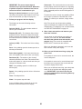
HOW TO USE THE MANUAL MODE
1. Begin pedaling or press any button on the
console to turn on the console.
See HOW TO TURN ON THE POWER on
page 18.
2. Select the manual mode.
When you turn on the console, the manual mode
will be selected automatically.
If you have selected a workout, reselect the manual
mode by pressing the Manual Control button.
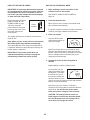
3. Enter your weight.
Press the Wt increase
and decrease buttons to
enter your weight.
Note: The console will use your weight to calcu-
late your approximate power output and calories
burned. If you do not enter your weight, the console
will use a default value to calculate your power
output and calories burned.
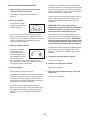
4. Change the incline of the training bike as
desired.
Begin pedaling to start the manual mode.
As you pedal, you can
change the incline of the
training bike. To change
the incline level, press
the Incline increase and
decrease buttons on the
console or press the Incline increase and decrease
buttons on the left handlebar.
Note: After you press a button, it will take a
moment for the training bike to reach the selected
incline level. You will hear the incline motor
while the incline is changing. This is normal.
CAUTION: The training bike can move to a
broad range of incline levels. Hold the handle-
bars and be prepared for the training bike to
move when you change the incline.
Reset
Position

19
5. Change the resistance of the training bike as
desired.
As you pedal, you can
change the resistance
to make pedaling easier
or harder. To change the
resistance level, press
the Resistance increase
and decrease buttons on the console or press the
Resistance increase and decrease buttons on the
right handlebar.
Note: After you press a button, it will take a
moment for the training bike to change to the
selected resistance level.
6. Do interval training, if desired.
As you exercise, you can alternate between
intervals of low-intensity (recovery) exercise
and intervals of high-intensity (work) exercise, if
desired.
To create a recovery interval, first adjust the incline
to the desired level. Then, press and hold the
Recovery button until two tones sound to save the
interval setting.
To create a work interval, first adjust the incline to
the desired level. Then, press and hold the Work
button until two tones sound to save the interval
setting.
As you exercise, press the Recovery and Work
buttons as desired to alternate between the saved
interval settings. After you press a button, the
incline level of the training bike will automatically
adjust to the level that you saved.
To change the interval settings at any time during
your workout, simply repeat this step.
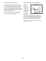
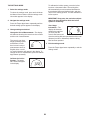
7. Follow your progress with the power ring, and
set a power output target, if desired.
The power ring
will provide a
visual representa-
tion of your power
output in watts
per kilogram of
body weight. As
your power out-
put increases or
decreases, a solid
bar will appear or
disappear in the
power ring.
To set a power output target, press the Watts/Kg
increase and decrease buttons until the desired
power output target appears in the display.
If you set a power output target during the
manual mode, a flashing indicator will appear in
the power ring to indicate your power output target.
As you exercise, adjust your pedaling speed, the
resistance level, and/or the incline level to keep
your power output near the power output target.
To change the power output target at any time
during your workout, simply repeat the actions
above.
Solid Bar
Power Output
Target
Actual Power
Output

20
IMPORTANT: The power output target is
intended only to provide motivation. Make sure
to pedal at a speed, a resistance level, and an
incline level that is comfortable for you.
During an onboard workout, the power ring will
show the preset power output target for each seg-
ment of the workout (see step 4 on page 21).
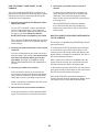
8. Follow your progress with the display.
The display can show the following workout
information:
Calories (CALS)—The approximate number of
calories you have burned.
Distance (MI or KI)—The distance that you have
pedaled in miles or kilometers. When the manual
mode is selected, the distance will count up. When
an onboard workout is selected, the distance will
count down.
Incline (% GRD)—The incline level of the training
bike.
Pace—Your pedaling speed in minutes per mile or
minutes per kilometer.
Pulse (heart symbol)—Your heart rate when you
wear a compatible heart rate monitor (see step 9).
Resistance (R)—The number of the currently
selected resistance level. Note: This workout infor-
mation will appear for a few seconds each time you
change the resistance level.
RPM—Your pedaling speed in revolutions per
minute (rpm).
Speed—Your pedaling speed in miles or kilometers
per hour.
Time—The elapsed time.
Watts—Your power output in watts.
Press the Display button repeatedly to view the
desired workout information in the display.
Scan mode—The console also has a scan mode
that will display workout information in a repeating
cycle. To select the scan mode, press the Display
button repeatedly until the word SCAN appears in
the display.
To pause the console, simply stop pedaling. When
the console is paused, the time will flash in the
display. To continue your workout, simply resume
pedaling.
Note: The console can show weight, pedaling
speed, and distance in standard or metric units of
measurement. To change the unit of measurement,
see THE SETTINGS MODE on page 24.
9. Wear a heart rate monitor and measure your
heart rate if desired.
You can wear an optional heart rate monitor to
measure your heart rate. For more informa-
tion about the optional heart rate monitor, see
page 22. Note: The console is compatible with
BLUETOOTH
®
Smart heart rate monitors.
When your heartbeat is detected, your heart rate
will be shown in the pulse display.
10. When you are nished exercising, unplug the
power cord.
If the pedals do not move for several seconds, the
console will pause.
If the pedals do not move for several minutes and
the buttons are not pressed, the console will turn
off and the display will be reset.
When you are nished exercising, press the power
switch to the off position and unplug the power
cord. IMPORTANT: If you do not do this, the
electrical components on the training bike may
wear prematurely.
Page is loading ...
Page is loading ...
Page is loading ...
Page is loading ...
Page is loading ...
Page is loading ...
Page is loading ...
Page is loading ...
Page is loading ...
Page is loading ...
Page is loading ...
Page is loading ...
-
 1
1
-
 2
2
-
 3
3
-
 4
4
-
 5
5
-
 6
6
-
 7
7
-
 8
8
-
 9
9
-
 10
10
-
 11
11
-
 12
12
-
 13
13
-
 14
14
-
 15
15
-
 16
16
-
 17
17
-
 18
18
-
 19
19
-
 20
20
-
 21
21
-
 22
22
-
 23
23
-
 24
24
-
 25
25
-
 26
26
-
 27
27
-
 28
28
-
 29
29
-
 30
30
-
 31
31
-
 32
32


Pro-Form LE TOUR DE FRANCE PFEX09916.1 User manual
- Type
- User manual
Ask a question and I''ll find the answer in the document
Finding information in a document is now easier with AI
Related papers
-
ProForm Le Tour De France PFEVEX71919.0 User manual
-
ProForm PFEVEX71516 User manual
-
-
-
Pro-Form 250 SPX User manual
-
-
-
-
-
Other documents
-
-
-
ProForm PFEVEX71916 Owner's manual
-
-
ProForm PFEVEX71413 Owner's manual
-
-
ProForm PFEX92220-INT Owner's manual
-
-
-