Page is loading ...

UHF Wireless Microphone System Kit
PDWM4350U - PDWM4360U
PDWM4350U
PDWM4360U

www.PyleUSA.com www.PyleUSA.com
CATALOG
1. FOREWORD --------------------------------------------------------------------------------------------- 2
2. INTRODUCTION
--------------------------------------------------------------------------------------- 2
3. SYSTEM FEATURES
----------------------------------------------------------------------------------- 2
4. SYSTEM TYPE
------------------------------------------------------------------------------------------- 2
5. FOUR CHANNEL RECEIVER FEATURES
-------------------------------------------------------- 3
6. TRANSMITTER FUNCTION & FEATURES
--------------------------------------------------- 4-5
7. TRANSMITTER BATTERY INSTALLATION
----------------------------------------------------- 6
8. BODYPACK TRANSMITTER CONNECTION
--------------------------------------------------- 7
9. SYSTEM CONNECTIONS
--------------------------------------------------------------------------- 8
10. TROUBLESHOOTING
----------------------------------------------------------------------------- 10
11. SPECIFICATIONS
----------------------------------------------------------------------------------- 11
SYSTEM COMPOSITION
1 2
Please read the instructions carefully to ensure proper use and operation
of the product. Also, keep the instructions for future reference.
This professional wireless microphone system operates on high-eciency,
low-consumption discharging techniques. Performance features include
independent developed mobile frequency compression, expander circuitry,
image frequency limiting circuits, a multiple checked silent and noise-free
circuit system, antenna diversity receiving circuit & switch impact noise defeat
circuits. Resis reverberation circuit and changed output control. Passes Q.C.
code standards.
SYSTEM FEATURES
1. Multiple System Use: Up to several UHF systems can be used in the same
performance space. Each system must be set at a dierent frequency.
(Frequency marked on the back of the receiver).
2. Simultaneous Output Use: Unbalanced 1/4" phone plug and balanced XLR
output connectors may be used simultaneously to dierent external devices.
3. Range: UHF Series transmitters will work at a distance of up to 50 meters
(about 164ft.) from the receiver.
4. Noise Squelch: Squelch circuit analyzes signal strength and quality so that it
can reduce the likelihood of noise burst due to environmental RF
(Radio Frequency) noise.
5. Low Battery Warning Light: A red light on the body-pack and hand-held
transmitters warns the user that there is less than one hour of battery life
remaining.
SYSTEM TYPE
The Vocal Artist-UHF is a hand-held system designed for singers who desire
the high quality of microphones and the freedom of wireless performance.
The Presenter-UHF is a body-pack system designed for public speakers who
prefer an inconspicuous, hands-free lavalier microphone.
The Headset-UHF is a body-pack system designed for users in physically
active applications, who desire the freedom of hand-free microphone.
The Guitarist-UHF is a body-pack system designed for use with electric
guilars, basses, and other electric instruments.
PDWM43SOU
PDWM4360U
Receiver
Receiver
(2)
Handheld Mics
(4)
Handheld Mics
(2)
Belt-Pack
Transmitters
DC Power
Adapter
(2)
Lavalier Mics
Rack Mount
Kit
(2)
Headset Mics
Batteries
DC Power
Adapter
Rack Mount
Kit
Batteries

www.PyleUSA.com www.PyleUSA.com
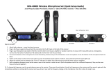
FOUR CHANNEL RECEIVER FEATURES
1. Power Button: Power ON/OFF the receiver.
2. Power Indicator: Indicate the power ON/OFF.
3. LCD Information Display: Show the receiver frequency channel ect.
4. Down Function Button: Sets channel data.
5. Up Function Button: Sets channel data.
6. "AF" Audio Level Indicator: Indicates the wireless system audio signal level.
7. "RF" Signal Indicator: It glows when the Receiver receive RF signal from
Transmitter.
8. Antenna.
9. XLR Balanced Output Jack: Connect the audio cable from this jack to
the input port of amplier, mixer.
10. Volume Knob: Adjust the volume output of receiver.
11. 1/4” Audio Output Jack: Connect the audio cable from this jack to the
Input port of amplier, mixer.
12. Power Jack: Connect the DC adapter to receiver.
3 4
MICROPHONE-TRANSMITTER FEATURES
1. Grille: Protects the cartridge and help reducing the breath sounds and wind
noise.
2. LCD Information Display: Show the transmitter frequency channel ect.
3. Down Function Button: Sets channel data.
4. Up Function Button: Sets channel data.
5. Power and Audio Mute Switch.
6. Battery Cover: Open it to install the battery.

www.PyleUSA.com www.PyleUSA.com
BODY-PACK TRANSMITTER FEATURES
1. Power and Audio Mute Switch.
2. Antenna: Transmit the RF signal of transmitter.
3. Belt Clip: Attach the transmitter to the belt.
4. Audio Input Jack: Suitable for lavalier system/headset system.
5. Low Battery Indicator: Red light glows when it is lack of power and should
renew the battery.
6. LCD Information Display: Show the transmitter frequency channelect.
7. Gain Adjusting Volume: Adjust the transmitter audio input gain.
8. State Setting Switch: Set the using state of lavalier system (L) / headset
system (H)
9. Up Function Button: Sets channel data.
10. Down Function Button: Sets channel data.
5 6
TRANSMITTER BATTERY INSTALLATION
1. Battery Installation of Handheld Microphone: Open the battery cover.
Insert the supplied batteries into battery jar in polarity and cover the battery.
2. Battery Installation of Bodypack Transmitter: Push open the battery
cover. Insert the supplied batteries into battery jar in polarity and close the
battery cover.

www.PyleUSA.com www.PyleUSA.com
BODYPACK TRANSMITTER CONNECTION
1. Lavalier Microphone Connection: Connect the connector of supplied
lavalier microphone to the connecting jack of transmitter (shown as below)
Set the transmitter work state in wireless lavalier system (L).
2. Headset Microphone Connection: Connect the connector of supplied
headset microphone to the connecting jack of transmitter (shown as below)
Set the transmitter work state in wireless headset system (H).
7 8
SYSTEM CONNECTION
1. Receiver Power Connection: Connect the DC connector of supplied AC/DC
adapter Into the DC power input of receiver. Plug the AC Input connecter
into an AC120/60Hz or AC220V/50Hz outlet. (Shown as below)
2. Antenna: Keep the position of antenna at a 45 angle from vertical.
(Shown as below)
3. Audio Connection: Connect the corresponding output of receiver by
supplied 1/4w phone jack audio cable or your XLR cable to the Input of
power amplier, mixer.

www.PyleUSA.com www.PyleUSA.com
TROUBLESHOOTING
9 10
SYSTEM SPECIFICATIONS
• RF Carrier Frequency Range:
Approximately 523 to 597.8 MHZ (Available frequencies depend on
applicable regulations in country where system is used).
• Operating Range: 50m (approximately 164ft) under typical conditions
• Audio Frequency Response: 100 to 18,000Hz, ±3dB
• THD: <1%
• Mobile state Range: > 100dB
Operating Temperature Range
-20.2°F to 165.2°F (-29°C to 74°C)
NOTE: Battery characteristics may limit this range.
OPTIONAL ACCESSORIES
1/4" to 1/4" Cable (The Guitarist -UHF only)
1/4" to Miniature Connector
1.8 Meter (6ft.) Receiver-Mixer Cable
RECEIVER SPECIFICATION
PROBLEM INDICATOR STATUS SOLUTION
No Sound
No Sound
No Sound
No Sound
No Sound
Sound level diers from
the level of a cabled
Instrument.
Sound level diers from
the level of dierent
guitars
Distortion level increases
gradually
Bursts of noise or other
audible radio signals
present
Momentary loss of
sound as transmitter is
moved around
performing area.
Receiver signal indicators
A/B lights glowing
Receiver signal indicators
A/E lights glowing
Signal indicators A/B
lights ON
Receiver signal
indicator A/B lights OFF
when sound is lost
Red transmitter
indicator is not
ashing
Red receiver POWER
light o
Receiver signal
indicators A/B lights
o. Transmitter and
receiver POWER lights
glowing
Receiver signal
indicators A/B lights
glowing
Red transmitter
indicator is ashing
Slide transmitter POWER ON/OFF switch
to ON position. Make sure battery is
inserted properly, observing battery (+/-).
If the battery is inserted properly, replace
with fresh battery.
Slide transmitter MUTE/ON switch to ON
position
Make sure AC adapter is securely
plugged into electrical outlet and into DC
input connector. Make sure AC electrical
outlet works and supplies proper voltage
Trun up receiver volume control. Conrm
that the output connections from the
receiver to the external equipment are
secure
Conrm transmitter and receiver~
frequency match. Move transmitter
closer to receiver.
Adjust transmitter gain level to
compensate.
Adjust receiver volume as necessary
Readjust transmittergain level to
compensate dierences in guitar outputs
Replace transmitter battery
Identify potential sources of interference
(other RF sources) and turn OFF, remove
or use a wireless system operating on a
dierent frequency
Reposition receiver and perform
walk-through again. If audio dropouts
persist, mark “dead” spot-and avoid them
during performance.
Receiver signal indicators
A/B lights and
transmitter LOW
BATTERY light glowing
Power Requirements
120
V
or
230
V
A
C
adaptor
with
2.
1
mm
femal
e
plug
Power Requirements
Signal/Noise
Ratio
MORE THAN
85dB
Border Upon Channel
Rejection
MORE
THAN
70dB
Image
& Spurious Rejection
MORE
THAN
70dB
Audio Output
Level
()
.±300mV
Receiving Sensitivity
-105dBm
Dimensions
12-15V DC nominal, 1000mA
394MM X 205MM X 52MM

www.PyleUSA.com www.PyleUSA.com
11 12
HAND-HELD TRANSMITTER SPECIFICATIONS
BODY-PACK TRANSMITTER SPECIFICATIONS
Power
Requirements
1.5VAA battery X
2
Nominal Current
Drain
LESS THAN 100mA
Modulation Type
FM
RF
Output
MORE THAN
1
0dBm
Max
Deviation
±70KHz
Spurious
Emission
MORE THAN
55dB
Dimensions
238MM X 50MM X 50MM
Power
Requirements
1.5VAA battery
X
2
Nominal Current
Drain
LESS THAN 100mA
Modulation
Type
FM
RF
Output
MORE THAN
1
0dBm
Max
Deviation
±70KHz
Spurious
Emission
MORE THAN
55dB
Dimensions
100MM X 65MM X 30MM
PDWM4350U
PDWM4360U
/