Page is loading ...

MODEL 8188 NETCLOCK/ETS
ETHERNET TIME SERVER
INSTRUCTION MANUAL
SPECTRACOM CORPORATION
95 Methodist Hill Drive
Suite 500
Rochester, NY 14623
PHONE 585-321-5800
FAX 585-321-5218
www.spectracomcorp.com
Copyright 2003 Spectracom Corporation. All rights
reserved. Contents of this publication may not be reproduced
in any form without the written permission of Spectracom
Corporation.
REVISIONS, IF ANY, ARE LOCATED AT THE END OF THE MANUAL
MANUAL REVISION 1.6
July 2003

5-Year Warranty
SPECTRACOM 95 Methodist Hill Drive Suite 500 Rochester, NY 14623 USA
+1.585.321.5800 FAX: +1.585.321.5218 www.spectracomcorp.com sa[email protected]
LIMITED WARRANTY________________________________
Spectracom warrants each new product manufactured and sold by
it to be free from defects in material, workmanship, and
construction, except for batteries, fuses, or other material normally
consumed in operation that may be contained therein, for five
years after shipment to the original purchaser (which period is
referred to as the "warranty period"). This warranty shall not
apply if the product is used contrary to the instructions in its
manual or is otherwise subjected to misuse, abnormal operations,
accident, lightning or transient surge, repairs or modifications not
performed by Spectracom.
The GPS receiver is warranted for one year from date of shipment
and subject to the exceptions listed above. The power adaptor, if
supplied, is warranted for one year from date of shipment and
subject to the exceptions listed above.
The Rubidium oscillator, if supplied, is warranted for two years
from date of shipment and subject to the exceptions listed above.
All other items and pieces of equipment not specified above,
including the antenna unit, antenna surge suppressor and antenna
pre-amplifier are warranted for 5 years, subject to the exceptions
listed above.
WARRANTY CLAIMS________________________________
Spectracom's obligation under this warranty is limited to in-factory
service and repair, at Spectracom's option, of the product or the
component thereof, which is found to be defective. If in
Spectracom's judgment the defective condition in a Spectracom
product is for a cause listed above for which Spectracom is not
responsible, Spectracom will make the repairs or replacement of
components and charge its then current price, which buyer agrees
to pay.
Spectracom shall not have any warranty obligations if the
procedure for warranty claims is not followed. Users must notify
Spectracom of the claim with full information as to the claimed
defect. Spectracom products shall not be returned unless a return
authorization number is issued by Spectracom. Spectracom
products must be returned with the description of the claimed
defect and identification of the individual to be contacted if
additional information is needed. Spectracom products must be
returned properly packed with transportation charges prepaid.
EXCEPT FOR THE LIMITED WARRANTY STATED ABOVE,
SPECTRACOM DISCLAIMS ALL WARRANTIES OF ANY KIND
WITH REGARD TO SPECTRACOM PRODUCTS OR OTHER
MATERIALS PROVIDED BY SPECTRACOM, INCLUDING
WITHOUT LIMITATION ANY IMPLIED WARRANTY OR
MERCHANTABILITY OR FITNESS FOR A PARTICULAR PURPOSE.
Spectracom shall have no liability or responsibility to the original
customer or any other party with respect to any liability, loss, or
damage caused directly or indirectly by an Spectracom product,
material, or software sold or provided by Spectracom,
replacement parts or units, or services provided, including but not
limited to any interruption of service, excess charges resulting from
malfunctions of hardware or software, loss of business or
anticipatory profits resulting from the use or operation of the
Spectracom product or software, whatsoever or howsoever
caused. In no event shall Spectracom be liable for any direct,
indirect, special or consequential damages whether the claims are
grounded in contract, tort (including negligence), or strict liability.
EXTENDED WARRANTY COVERAGE___________________
Extended warranties can be purchased for additional periods
beyond the standard five-year warranty. Contact Spectracom no
later than the last year of the standard five-year warranty for
extended coverage.

TABLE OF CONTENTS
1.0 INTRODUCTION.........................................................................................................................................................................1
2.0 WARRANTY INFORMATION AND PRODUCT SUPPORT ..................................................................................................2
3.0 UNPACKING................................................................................................................................................................................3
4.0 INSTALLATION OVERVIEW-------------------------------------------------------------------------------------------------------- … 3
5.0 NETWORK PARAMETERS ---------------------------------------------------------------------------------------------------------… 4
6.0 CONFIGURATION ------------------------------------------------------------------------------------------------------------------------ 7
6.1 RS-232 Connection 7
6.2 Telnet Connection 9
6.3 Configuration Menus 10
6.3.1 Basic Configuration 10
6.3.2 NetClock Configuration ........................................................................................................................... 11
6.3.3 Security Options 12
7.0 CONNECTING TO A NETCLOCK MASTER CLOCK -------------------------------------------------------------------------- . 14
7.1 Connecting to a GPS NetClock or TimeBridge 14
7.2 Connection to NetClock/GPS or TimeBridge 15
8.0 CONNECTING TO THE NETWORK------------------------------------------------------------------------------------------------- 16
9.0 NTP CLIENT SOFTWARE-------------------------------------------------------------------------------------------------------------- 17
10.0 SYNC STATUS LAMP .------------------------------------------------------------------------------------------------------------------ 18
11.0 REAR PANEL FUNCTIONS----------------------------------------------------------------------------------------------------------- . 19
11.1 RS-232 Setup 19
11.2 10 Base-T Port 20
11.3 RS-485 Input Port 21
11.3.1 Cable Selection 22
11.3.2 Connection Method 22
11.3.3 Termination 24
11.4 Input Power 25

ILLUSTRATIONS
FIGURE 1 MODEL 8188 NETCLOCK/ETS 1
FIGURE 2 ENTERING SETUP MODE 7
FIGURE 3 SETUP MENU SELECTIONS 8
FIGURE 4 INITIAL TELNET CONNECTION EXAMPLE 10
FIGURE 5 RS-485 INPUT CONNECTOR 14
FIGURE 6 CONNECTION TO A GPS NETCLOCK OR TIMEBRIDGE 15
FIGURE 7 NETCLOCK/2 REMOTE OUTPUT 15
FIGURE 8 CONNECTION TO A NETCLOCK/2 MASTER CLOCK 15
FIGURE 9 10 BASE-T CONNECTOR 16
FIGURE 10 NETCLOCK/ETS FRONT PANEL 18
FIGURE 11 NETCLOCK/ETS REAR PANEL 19
FIGURE 12 SETUP PORT PIN NUMBERING 19
FIGURE 13 ONE-WAY BUS INSTALLATION 23
FIGURE 14 SPLIT BUS CONFIGURATION 23
FIGURE 15 WIRE STRAIN RELIEF 24
FIGURE 16 TERMINATION RESISTOR 25
TABLES
TABLE 1 MODEL 8188 ANCILLARY KIT 3
TABLE 2 DEFAULT NET MASKS 5
TABLE 3 EQUIVALENT NET MASK TABLE 5
TABLE 4 PIN ASSIGNMENTS 20
TABLE 5 CABLE SOURCES FOR RS-485 LINES OVER 1500 FEET 22
TABLE 6 CABLE SOURCES FOR RS-485 LINES UNDER 1500 FEET

Model 8188 NetClock/ETS Instruction Manual - 1 -
Model 8188 ETHERNET TIME SERVER
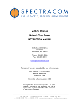
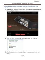
1.0 INTRODUCTION
The Spectracom
Model 8188 shown in Figure 1 is a Stratum 1 NTP Time Server when
connected to a Spectracom NetClock
Master clock. Spectracom Master Clocks receive
accurate and traceable time from WWVB or GPS. All NetClock Master Clocks have a
continuous RS-485 once-per-second time data output port. This output is typically used to
synchronize Spectracom accessory products such as TimeView
display clocks,
TimeTap
RS-485 to RS-232 converters and Model 8188 Ethernet Time Servers.
The Model 8188 supports the most popular time distribution protocols, NTP, SNTP and
UDP/Time. To make the Model 8188 operational the unit is first configured with network
parameters such as IP address, gateway IP address, net mask, etc. Configuration is
done using the RS-232 Setup port connection or over the network using Telnet. Upon
completing the configuration, the Model 8188 is then connected to a NetClock Master
Clock. The Model 8188 is now ready to provide time to hundreds of computers installed
throughout the network.
FIGURE 1 MODEL 8188 NETCLOCK/ETS
Spectracom
, NetClock
, TimeView
and TimeTap
are trade marks of Spectracom Corporation. All other
products are identified by trademarks of their respective companies or organizations.
NetClock/ETS Ethernet TimeServer
SYNC STATU
S

- 2 - Model 8188 NetClock/ETS Instruction Manual
2.0 WARRANTY INFORMATION AND PRODUCT SUPPORT
Warranty information is found on the leading pages of this manual. The Model 8188
contains a network interface card that is not manufactured by Spectracom Corporation,
and therefore shall carry a one-year warranty. In addition, the AC power adapter carries a
one-year warranty. Should it become necessary to exercise the warranty, contact
Spectracom Corporation to obtain a replacement or service.
Spectracom continuously strives to improve its products and therefore greatly appreciates
any and all customer feedback given. Please participate in Spectracom’s Customer
Satisfaction Survey found on our web site at:
http://www.spectracomcorp.com
The online survey is also used for warranty registration of your new Spectracom products.
All completed entries are automatically entered into a monthly prize give away drawing.
Technical support is available by telephone. Please direct any comments or questions
regarding application, operation, or service to Spectracom Customer Service Department.
Customer Service is available Monday through Friday from 8:30 A. M. to 5:00 P.M.
Eastern time.
Telephone Customer Service at: 585-321-5800.
In addition, please contact customer service to obtain a Return Material Authorization
Number (RMA#) before returning any instrument to Spectracom Corporation. Please
provide the serial number and failure symptoms. Transportation to the factory is to be
prepaid by the customer. After obtaining an RMA# ship the unit back using the following
address:
Spectracom Corporation
Repair Department, RMA# xxxxx
95 Methodist Hill Drive, Suite 500
Rochester, NY 14623
Product support is also available by e-mail. Questions on equipment operation and
applications may be e-mailed to Spectracom Sales Support at:
Repair or technical questions may be e-mailed to Spectracom Technicians at:
Visit our web page for product information, application notes and upgrade notices as they
become available at:
http://www.spectracomcorp.com

Model 8188 NetClock/ETS Instruction Manual - 3 -
3.0 UNPACKING
Upon receipt, carefully examine the carton and its contents. If there is damage to the
carton that results in damage to the unit, contact the carrier immediately. Retain the carton
and packing materials in the event the carrier wishes to witness the shipping damage.
Failing to report shipping damaging immediately may forfeit any claim against the carrier.
In addition, notify Spectracom Corporation of shipping damage or shortages, to obtain a
replacement or repair services.
Remove the packing list from the envelope on the outside of the carton. Check the
packing list against the contents to be sure all items have been received, including an
instruction manual and ancillary kit. Table 1 lists the items included in the Model 8188
ancillary kit.
Description Part Number Quantity
Terminal Block, 3-position P13003 1
AC Adapter, 12 VDC, 1 Amp T00058 1
Terminating Resistor, 120Ω
R02121 1
TABLE 1 MODEL 8188 ANCILLARY KIT
4.0 INSTALLATION OVERVIEW
The installation of the NetClock/ETS can be broken down into seven basic steps.
1) Select a location for the Model 8188 where access to an AC power receptacle,
connection to a network hub and connection to the NetClock Master Clock’s
RS-485 time broadcast are available. A 19-inch rack mount kit is available for
the Model 8188. Contact Spectracom for additional information on the Option
03 Rack Mount Kit.
2) Apply power to the Model 8188.
3) Configure the Model 8188 network parameters such as IP address, gateway IP
address, net mask, security features, etc. using an RS-232 or Telnet
connection. Review the network parameters as described in Section 5 with
your network administrator to avoid improper setup. Section 6 describes the
Model 8188 configuration procedure.

- 4 - Model 8188 NetClock/ETS Instruction Manual
4) Configure the NetClock Master Clock’s RS-485 port to provide either Data
Format 0 or Format 2 at 9600 baud. When using Data Format 0, be certain to
select the appropriate time difference and DST rule configurations to provide
“local time” to the Model 8188. Refer to Section 7 for information on NetClock
configuration.
5) Connect the Model 8188 to the NetClock Master Clock’s RS-485 output data
stream. This connection can be made directly at the NetClock Master Clock
rear panel or anywhere along the RS-485 bus by tapping into the cable. Refer
to Section 7 for information on connecting to the NetClock Master Clock.
6) Connect the Model 8188 to a 10 Base-T hub or switch on the network using a
straight through RJ-45 cable.
7) Install and configure the NTP or SNTP client software on the servers and
workstations where required. Refer to Section 9 for NTP application
information.
5.0 NETWORK PARAMETERS
When configuring the Model 8188, there are parameters that will be unique to each
network. Please review the following configuration parameters A through G with your
network administrator:
A. IP Address - This is the unique 32-bit address assigned to the Model 8188
by the network administrator. The default IP address is 192.168.000.039.
Note: The reserved Network and Broadcast addresses cannot be
assigned to the Model 8188 (host address). For example, the host
address of .000 is used to identify the entire network and .255 identifies
the broadcast address.
B. Gateway Address - The gateway/router address is needed if
communication to the Model 8188 is made outside the local network. By
default, the gateway is disabled.
C. Subnet Mask - A subnet mask allows routers and gateways to handle
packets quicker by eliminating the need to process the host bits contained in
the IP address. The subnet mask defines the number of bits taken from the
IP address that are used in the host portion.

Model 8188 NetClock/ETS Instruction Manual - 5 -
The default host bit value is 00. Setting the host bit value to 00 allows
automatic selection of the appropriate default net mask based on the IP
address used. The default subnet mask for each of the common network
classes is shown in Table 2.
Network
Class
IP Address Range Host
Bits
Default Subnet
Mask
A 1.x.x.x to 127.x.x.x 24 255.0.0.0
B 128.0.x.x to 191.255.x.x 16 255.255.0.0
C 192.0.0.x to 223.255.255.x 8 255.255.255.0
TABLE 2 DEFAULT NET MASKS
The number of host bits used in the net mask can range from 2 to 24 bits.
Table 3 provides the complete list of the number of host bits and the
corresponding subnet mask.
TABLE 3 EQUIVALENT NET MASK TABLE
D. SNMP Address - S
imple Network Management Protocol allows monitoring
of the NetClock/ETS status over the network. Up to two IP addresses for
SNMP managers can be specified. By default SNMP is disabled and the IP
addresses are set to 0.0.0.0. When the SNMP feature is enabled an SNMP
Community Name of up to 13 characters can be assigned. MIB II per RFC
1213 is supported. Refer to section 11.2 for additional information.
Host E
q
uivalent Net mask Host E
q
uivalent Net mask
2
255.255.255.252
14
255.255.192.0
3 255.255.255.248 15 255.255.128.0
4 255.255.255.240 16 255.255.0.0
5 255.255.255.224 17 255.254.0.0
6 255.255.255.192 18 255.252.0.0
7 255.255.255.128 19 255.248.0.0
8 255.255.255.0 20 255.240.0.0
9
255.255.254.0 21 255.224.0.0
10 255.255.252.0 22 255.192.0.0
11 255.255.248.0 23 255.128.0.0
12 255.255.240.0 24 255.0.0.0
13 255.255.224.0

- 6 - Model 8188 NetClock/ETS Instruction Manual
E. Reference Identifier- This feature when enabled, places up to four
characters in the NTP header to identify the Model 8188 as the time source.
For example, when the Model 8188 is connected to a Spectracom GPS
based master clock the Reference Identifier can be set to “GPS”. When the
Model 8188 is connected to a Spectracom WWVB based master clock the
Reference Identifier can be set to “WWVB”.
F. Encryption - When authentication is required, up to six MD5 or DES keys
can be set. All key inputs are in hexadecimal format. Each key number
(1...6) consists of up to eight 8-bit groups. Factory default disables
encryption.
NOTE: The Encryption feature does not mean that the
time packet will be encrypted. This feature is used to
authenticate that the received time packet came from the desired
time-server. To use this feature, both the 8188 and the NTP
client use the same MAC key. When the NTP client requests the
time, the Model 8188 appends the time packet with the
authentication key.
G. Security Settings- The Model 8188 offers the following security features:
Telnet Password - A Telnet password may be implemented to prevent
unauthorized access of the NetClock/ETS configuration over the network. A
password can be up to 16 characters long and may be any combination of
letters, numbers or keyboard symbols. The default is "No Telnet Password
Selected".
NOTE: The RS-232 setup port is not password protected.
Password protection is only applicable for Telnet connections.
Telnet Disable- This feature prevents any telnet configuration session.
Future configuration changes must be made using the RS-232 Setup port
when this feature is selected. By default, telnet configuration is enabled.
TFTP Disable- Firmware upgrades are made using a binary file from a
TFTP client. If the TFTP port is disabled no firmware downloads are
possible. By default TFTP operation is enabled.

Model 8188 NetClock/ETS Instruction Manual - 7 -
6.0 CONFIGURATION
The Model 8188 can be configured using its RS-232 Setup port or through a Telnet
connection. Refer to Section 6.1 for the RS-232 connection method and Section 6.2 for
Telnet connection instructions. Both communication methods access the same
configuration menus. Refer to Section 6.3 for a description of the configuration menus.
6.1 RS-232 Connection
Connect a terminal or computer running a terminal emulation program (HyperTerminal,
ProComm, etc.) to the RS-232 Setup port. Connect using a straight through (1 to 1
pinning) RS-232 serial cable. Configure the terminal for ANSI emulation, 9600 baud, 8
data, 1 stop, no parity and no flow control.
To enter the RS-232 configuration mode the Model 8188 must be power cycled off and
then back on. While powering the unit on, hold down the lowercase “x” key on the
terminal or computer. When a connection has been established, the unit responds as
shown in Figure 2 prompting the user to depress the enter key to begin the Setup Mode.
NOTE: To enter the RS-232 configuration mode the Model 8188
must first be turned off. Then depress and hold down the lowercase
“x” key while reapplying power. The unit will prompt you to press the
Enter key to begin the Setup Mode.
NOTE: The keyboard Caps Lock and Scroll Lock functions must
be turned off to access Setup Mode.
FIGURE 2 ENTERING SETUP MODE

- 8 - Model 8188 NetClock/ETS Instruction Manual
NOTE: The Enter key must be depressed within 5 seconds to
access the Setup Mode menus. After 5 seconds the Model 8188 times
out and responds with the characters “?!?”. The unit will have to be
power cycled and sent the “x” character again to access Setup Mode.
Upon pressing the Enter key, the unit responds with its current configuration and menu
change options as shown in Figure 3.
*** basic configuration
Hardware: Ethernet Autodetect
IP addr : 192.168.0.39, no gateway set
*** NetClock configuration
Antenna type : Spectracom Type 0 (present year 2002)
SNMP : disabled
SNMP Community Name :
SNMP manager IP's : --- not set --- --- not set ---
Syslog IP addr : --- not set --- --- not set ---
Syslog file : LOCAL0
Encryption : disabled
*** Security
Telnet Setup : enabled
TFTP Download : enabled
WEB Manager : disabled
Web Server : disabled
Password : disabled
Change Setup : 0 Basic configuration
1 NetClock configuration
6 Security
7 Factory defaults
8 Exit without save
9 Save and exit Your choice ?
FIGURE 3 SETUP MENU SELECTIONS

Model 8188 NetClock/ETS Instruction Manual - 9 -
6.2 Telnet Connection
This section describes how to set a static ARP using the hardware address and the
desired IP address. The hardware address is found on the label affixed to the bottom
cover. The ARP command is available with UNIX and Windows 2000, NT, 95 or 98 using
the DOS or Command prompt.
NOTE: There must be at least one entry in the ARP table, other
than the local machine, for the ARP command to work in Windows. To
view the current ARP table, type ARP -A at the DOS command prompt.
If only the local machine is listed, build the ARP table by pinging to
another IP address in your network.
In the following example, the desired IP address is 192.168.0.34 and the Model 8188
hardware address is 00 20 4A 72 34 02. The initial Telnet session is shown in Figure 4.
1. Issue the ARP -S command using the desired IP address and hardware
address. From the DOS or Command prompt enter the IP address in decimal
dot notation format and the hexadecimal hardware address separated by
hyphens (-).
c:\ >arp -s 192.168.0.34 00-20-4a-72-34-02 <ent>
In UNIX enter the desired IP address in decimal dot notation format and the
hexadecimal hardware address separated by colons (:).
arp -s 192.168.0.34 00:20:4a:72:34:02 <ent>
2. Open a Telnet connection of the desired IP address to Port Number 1. Note that
this connection will fail, but the Model 8188 IP address will be forced to the
desired value.
c:\>telnet 192.168.0.34 1 <ent>
3. Open a Telnet connect using the desired IP address and Port Number 9999.
This time, the connection will be successful, allowing access to Telnet
configuration menu.
c:\>telnet 192.168.0.34 9999
NOTE: If the Telnet connection is unsuccessful repeat the
connection to Port 9999 and the desired IP address. If the connection
continues to fail the Telnet feature may have been disabled or been
password protected. Use the RS-232 connection to configure the
NetClock/ETS.

- 10 - Model 8188 NetClock/ETS Instruction Manual
Once a successful connection is made, you will be prompted to press the enter key or
type in the Telnet password if previously set. Your response must occur within 5 seconds
or the Telnet connection will time out.
FIGURE 4 INITIAL TELNET CONNECTION EXAMPLE
6.3 Configuration Menus
Once a successful RS-232 or Telnet connection has been made the current configuration
and menu options are given as shown in Figure 3. The configuration menus are divided
into three categories; Basic Configuration, NetClock Configuration and Security options.
Upon completion of each menu an option is given to select another configuration menu or
to save and exit with or without saving the configuration. The following paragraphs
describe each of the menu selections.
6.3.1 Basic Configuration
Select 0 for Basic Configuration. After each parameter, the current configuration is shown
in parentheses. To accept the variable, press the Enter key. To change the variable
simply type in the new value then press the Enter key. The configuration menu will
advance to the next parameter. It is not necessary to depress the Enter key when a Yes
or No option is given, type y for yes and n for no.
Address variables are entered in a decimal dot notation format. It is not necessary to type
leading zeroes in the address. For example, an IP address of 192.000.023.007 can be
entered using 192.0.23.7.
Invalid or improperly formatted entries are rejected, requiring the parameter to be entered
again. Upon completion of the Setup, an option to load and save the changes is given
(option 9). After the configuration is loaded (or re-loaded), the current configuration of the
Model 8188 is echoed back.

Model 8188 NetClock/ETS Instruction Manual - 11 -
The Basic configuration setup includes the following setup parameters:
IP Address - This is the 32-bit address assigned to the Model 8188 by the network
administrator. The default IP address is 192.168.000.039. The IP address is divided into
four octets with the current value shown in parentheses. Enter each octet in decimal dot
notation as shown in the example below to change the IP address to 131.123.070.146:
IP Address: (192) 131. (168) 123. (000) 70 (039) 146 <ent>
Gateway Address - A Yes/No option is given to enable a gateway address. If the
application does not require a gateway, select N. To set a gateway, type Y and edit the
address prompts as described above.
Subnet Mask - The subnet mask defines the number of bits taken from the IP address
that are used in the host portion. The default host bit value is 00. Setting the host bit
value to 00 allows automatic selection of the appropriate net mask based on the IP
address used. Refer to Table 2 for the default subnet mask for the common network
classes and Table 3 for the complete listing of net mask values.
6.3.2 NetClock Configuration
Select 1 to enter the NetClock Configuration menu. This configuration menu includes the
following setup parameters:
Spectracom Format: This parameter selects the Spectracom Data Format provided to
the Model 8188. The Model 8188 accepts either Format 0 or Format 2.
NOTE: Verify the NetClock RS-485 port is configured to provide the
selected Data Format. Refer to Section 7 for additional information.
Enter Current Year: This parameter only appears if Data Format 0 is the selected in the
previous step. Since Format 0 does not contain year data, the current year must be set.
Disable SNMP: A Yes / No option is given to enable SNMP with MIB II support per RFC
1213. Select Y if SNMP is not utilized. To enable SNMP type N.
When the SNMP feature is enabled a prompt to enter the SNMP community name is
given. The community name can be up to 13 characters long. Access to the
NetClock/ETS database is limited to this name.
Change Reference Identifier: A Yes / No option is given to change the Reference
Identifier. The Reference Identifier can be up to 4 characters and appears in the NTP
header to identify the NetClock/ETS.

- 12 - Model 8188 NetClock/ETS Instruction Manual
SNMP Address: Up to two SNMP Manager IP addresses can be specified. Upon
completion of the first SNMP IP address a prompt is given to enable the second SNMP
manager. Each IP address is divided into four octets with the current value shown in
parentheses. Enter each octet in decimal dot notation as shown in the example below to
configure the IP address to 131.123.090.005:
IP Address: (000) 131. (000) 123. (000) 90 (000) 5 <ent>
NOTE: The SNMP feature must be Enabled in previous steps to
fully implement the function.
Syslog Address: A Yes / No option is given to enable up to two Syslog IP addresses.
NOTE: The Syslog feature is not supported in the Model 8188
NetClock/ETS. Select NO to disable this feature.
Encryption: A Yes / No option is given to enable MD5 DES authentication algorithms.
Type N to disable encryption or Y to enable. Up to six keys of 8 bytes can be configured
when prompted.
MAC Keys: If encryption was enabled in the previous step, up to six keys may be
configured. All key inputs are in hexadecimal format. The keys are divided into eight
bytes with the current byte value shown in parentheses. Enter each byte followed by a
space as shown in the example below:
Enter Mac Key #1 (00) A1 (00) 3F (00) 01 (00) 2D (00) 33 (00) ED (00) 60 (00) BF <ent>
Upon completion of the NetClock Configuration setup, the current configuration is echoed
back and the option to continue or exit is given. Select 6 to enter the Security Menu if
configuration changes are required. Select 9 to save the Basic and NetClock
configurations and exit from the setup mode.
6.3.3 Security Options
Select 6 to enter the Security Configuration menu. This configuration menu includes the
following parameters:
Disable Telnet: A Yes / No option is given to disable Telnet configuration sessions. Type
Y to disable Telnet or select N to permit Telnet sessions. If Telnet is disabled future
configuration changes must be made using the RS-232 Setup port. By default, Telnet
configuration is enabled.

Model 8188 NetClock/ETS Instruction Manual - 13 -
Disable TFTP: A Yes / No option is given to disable TFTP port operation. Firmware
upgrades are made using a binary file from a TFTP client. If the TFTP port is disabled no
firmware downloads are possible. Type Y to disable TFTP or N to enable firmware
downloads. By default TFTP operation is enabled.
Disable Web Manager and Disable Web Server: A Yes / No option is given to disable
Web Manager and Server functions. These functions are reserved for future
implementation and are currently unsupported. Select Y to disable these features.
Note: The Web Manager and Web Server functions are not
supported in the Model 8188 NetClock/ETS. To assure proper
operation select Y to disable these features.
Telnet Password: A Yes / No option is given to enable a Telnet password. The
password prevents unauthorized access of the NetClock/ETS configuration over the
network. By default the Telnet port is not password protected.
NOTE: The RS-232 setup port is not password protected.
Password protection is only applicable for Telnet connections.
To enable a password type Y and enter the desired password. A password can be up to
16 characters long and may be any combination of letters, numbers or keyboard symbols.
To change a password type Y in the Enable Password option. A Yes / No option is given
to Change the Password, type Y and enter the new password.
To remove password protection type N in the Enable Password option.
This completes the NetClock/ETS configuration, select option 9 to Save and Exit the
configuration. The Model 8188 will update and store the selected parameters into non-
volatile memory. The Model 8188 is now ready for connection to a NetClock Master
Clock.

- 14 - Model 8188 NetClock/ETS Instruction Manual
7.0 CONNECTING TO A NETCLOCK MASTER CLOCK
The Model 8188 only accepts Spectracom Data Formats 0 or 2 at a port speed of 9600
baud. Verify the NetClock Master Clock is configured to output the same Data Format
that was selected during the Model 8188 configuration.
NOTE: The Model 8188 can be configured to accept either Data
Format 0 or 2 from a Spectracom NetClock Master Clock. The
NetClock RS-485 port speed must be set to 9600 baud.
All Spectracom GPS synchronized NetClocks are configured using their RS-232 Serial
Setup port. Model 8182 NetClock/2 WWVB Master Clock and the Model 8186
TimeBridge utilize setup switches to select Data Format and baud rate configuration.
Refer to the appropriate instruction manual for a complete description on clock
configuration.
The Model 8188 connects to the NetClock Master Clock through the 3-position terminal
strip connector labeled RS-485. This connector, shown in Figure 5, is furnished in the
ancillary kit. Section 7.1 describes how to connect to a GPS NetClock or TimeBridge.
Section 7.2 describes the connection to a NetClock/2 Master Clock. For additional
information on RS-485 cabling, termination and interconnection to other Spectracom
products refer to Section 11.3.
FIGURE 5 RS-485 INPUT CONNECTOR
7.1 CONNECTING TO A GPS NETCLOCK OR TIMEBRIDGE
Model 8183 NetClock/GPS and Model 8186 TimeBridge provide the RS-485
synchronizing data stream on a 3-position terminal strip. Connect the Model 8188 to
these products as shown in Figure 6. The front panel Sync Status lamp on the Model
8188 will change to a steady green when the unit has acquired time synchronization to the
Master Clock.
To simplify installation Spectracom offers an interface cable with 3-position terminal strip
connectors on each end. Specify part number CA15003 for a three-foot long cable and
CA15006 for a six-foot cable.

Model 8188 NetClock/ETS Instruction Manual - 15 -
FIGURE 6 CONNECTION TO A GPS NETCLOCK OR TIMEBRIDGE
7.2 CONNECTING TO A NETCLOCK/2 MASTER CLOCK
The Model 8182 NetClock/2 provides the RS-485 time data stream on its Remote Output
connector. The Remote Output connector is a DB9 female. Refer to Figure 7 for
connector pin numbering.
FIGURE 7 NETCLOCK/2 REMOTE OUTPUT
Connect the Model 8188 to the NetClock/2 Remote Output as shown in Figure 8. The
front panel Sync Status lamp on the Model 8188 will change to a steady green when the
unit has acquired time synchronization to the NetClock/2.
FIGURE 8 CONNECTION TO A NETCLOCK/2 MASTER CLOCK

- 16 - Model 8188 NetClock/ETS Instruction Manual
8.0 CONNECTING TO THE NETWORK
Using a straight through RJ-45 cable connect the Model 8188 10 Base-T port to a hub on
the network. The upper left LED indicator on the 10 Base-T connector, shown if Figure 9,
will illuminate when a Good Link (GL) is detected.
NOTE: The upper left LED indicates Good Link when illuminated. The
LED on the right is not utilized and will never illuminate.
FIGURE 9 10 BASE-T CONNECTOR
Once the Model 8188 has been correctly configured to operate on your network, you can
verify its operation by using the DOS ping command. From a DOS session issue the ping
command as shown below except substitute the IP address used by the Model 8188.
Ping 194.168.37.41
If the connection is successful the unit shall reply as follows:
Reply from 194.168.37.41: bytes=32 time=1ms TTL=32
Reply from 194.168.37.41: bytes=32 time=2ms TTL=32
Reply from 194.168.37.41: bytes=32 time=1ms TTL=32
Reply from 194.168.37.41: bytes=32 time=1ms TTL=32
If the ping response indicates a failure verify the Model 8188 IP address and gateway
address (if used) is correct.
/