Pulsar PS401203 Operating instructions
- Category
- Power supply units
- Type
- Operating instructions
This manual is also suitable for

1
Enclosed switch mode power supplies
PS401203, PS601250,
PS1001207, PS15012100
EN
Edition: 3rd from 16.04.2011
Supercedes edition: 2nd z from 15.11.2010
1. Technical description.
1.1 General characteristics.
The power supply units are intended for the feeding of alarm system equipment, which requires uninterruptible
supply of 12VDC voltage, provided by 230VAC mains. Their design enables simple switching of the output voltage, within
the range of 12÷15VDC, using a potentiometer. The power supply units are protected against short-circuit, overload and
overvoltage.
1.2 Technical parameters.
PS401203 PS601250 PS1001207 PS15012100
Dimensions (L x W x H)
129 x 98 x 40mm 160 x 98 x 39mm 199 x 98 x 39mm 191 x 110 x 50mm
Net/Gross weight
0,375kg / 0,395kg 0,480kg / 0,510kg 0,640kg / 0,670kg 0,730kg/ 0,775kg
Input voltage
85 ÷ 264 V AC
120 ÷ 370 V DC
85 ÷ 264 V AC
120 ÷ 370 V DC
170 ÷ 264 V AC 176 ÷ 264 V AC
Leakage current
<0,7mA / 230 VAC <0,7mA / 230 VAC <0,7mA / 230 VAC <0,7mA / 230 VAC
Output voltage
12 V ÷ 15V DC (12V factory settings)
Output power
40W 60W 100W 150W
Output current
for t
AMB
< 30°C
3,0 A* 5,0 A* 7,0 A* 10,0 A*
Output current
for t
AMB
= 40°C
2,1 A* 3,5 A* 4,9 A* 7,0 A*
Output ripple
<100mV <100mV <100mV <100mV
Short circuit protection
YES YES YES YES
(shut off: reset requires
disconnecting load or
supply for about 5 s.)
Overload protection
110% - 150%
output power
105% - 150%
output power
110% - 130%
output power
105% - 150%
output power
(shut off: reset requires
disconnecting load or
supply for about 5 s.)
Overvoltage protection
YES YES YES YES
(shut off: reset requires
disconnecting supply for
about 20 s.)
Operation conditions
0
o
C ÷ 40
o
C , RH 20 ÷ 90 %, no condensation
REMARKS
1-st Protection Class
REMARKS:
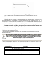
Output current (*):
Maximum continuous output current depends of the ambient temperature – refer to graph 1.

2
Graph 1. Relation between ambient temperature and maximum continuous output current of the PSU.
2. Installation.
2.1 Requirements.
The power supply shall be mounted by the qualified installer having appropriate (required and necessary for a
given country) permissions and qualifications for connecting (operating) low-voltage installations. The unit shall be
mounted in closed rooms, according to the environment class II, of the normal air humidity (RH=90% max. without
condensation) and the temperature within the range from 0°C to +40°C.
The power supply shall be mounted in a close casing (a cubicle, a terminal device) and in order to fulfill LVD and
EMC requirements the rules for power-supply, encasing and shielding shall be observed according to application.
Due to the power supply design, the PE wire has to be connected to the corresponding connector of the
supply unit. Operation without proper grounding of the power supply is not allowed!
2.2 Installation procedure.
1. Prior to installation of the power supply unit, make sure that power leads have been disconnected from the
230VAC mains.
2. Install the unit in the previously selected place.
3. Connect the 230VAC power leads. Connect the PE cable (yellow-green) to an appropriate terminal on the power
supply unit (marked with ).
The circuit of the shock protection shall be performed with a particular care, i.e. the yellow and green
protection wire of the power cable shall be connected from one side to the terminal marked by the
symbol of in the casing of the power-supply. Operation of the power-supply without the properly
made and fully operational circuit of the shock protection is
UNACCEPTABLE!
It can result in failure of devices and electric shock.
4. Connect load/loads to proper output junctions of the power supply unit (positive end is marked as V+, negative end as
V- or COM).
5. Upon the completion of tests and trial activation, close the housing, cabinet etc.
Connectors/elements description:
Elements/terminals Description
L, N, PE
L-N - input voltage conectors 230 V AC,
PE – protective conductor connector
V- (COM)
Output ground (0V)
V+
Power supply output (+12V)
LED D1 (LED1)
Diode signals the presence of voltage at the unit’s output
P1 (VR1)
Potentiometer - output voltage adjust

3
3. Maintenance.
All maintenance operations can be carried out only if the unit has been disconnected from the power network.
The unit does not require any particular maintenance. However, clean with compressed air, if heavily dusted.
WEEE designation
The waste electric and electronic equipment worn out may not be disposed of together
with standard household waste. According to the WEEE directive, applicable in the EU, the
separate neutralization methods should be used for electric and electronic equipment.
Pulsar K.Bogusz Sp.j.
Siedlec 150, 32-744 Łapczyca, Poland
Tel. (+48) 14-610-19-40, Fax. (+48) 14-610-19-50
e-mail: [email protected], sa[email protected]l
http://
www.pulsar.pl
THE GENERAL WARRANTY CONDITIONS
1. Pulsar K. Bogusz, Particular Partnership (the manufacturer) provides a one-year quality warranty for devices, as from the
purchase date placed on a purchase proof.
2. The warranty includes free repair or replace for a functional equivalent (the selection is performed by the manufacturer) of a
non-operational device due to reasons dependent on the manufacturer, including production and material defects, as far as
defects are notified within the warranty period (item 1 and 2).
3. The equipment subject to warranty shall be provided to the point, where it has been purchased or directly to the place of
business.
4. The complete devices are subject to warranty, and the sort of defect shall be described in written in a correctly fulfilled claim
notification.
5. If a claim is accepted, the manufacturer is obliged to perform warranty repairs as soon as possible, but no later than 14 working
days since the device is provided to the service of the manufacturer.
6. The repair period specified in item 5 can be extended, if there are no technical opportunities to perform the repair or the
equipment is conditionally accepted by the service due to non-compliance of the warranty conditions by the person lodging a
claim.
7. All service actions related to warranty are performed exclusively at the service of the manufacturer.
8. The warranty does not include the following defects of the device due to:
- manufacturer-independent reasons,
- mechanical defects,
- improper storage and transport,
- operation contrary to the instruction manual or purpose of the device,
- emergencies, including atmospheric discharges, failures of the power network, fire, flood, effect of high temperature and
chemical agents,
- improper installation and configuration (contrary to the instruction manual)
9. The loss of rights resulting from the warranty always occurs, if it is confirmed that construction changes have been performed or
repairs have not been performed at the service of the manufacturer, or if serial numbers or warranty labels of the device are
somehow replaced or damaged.
10. The responsibility of the manufacturer towards the purchaser is limited to the value of the device determined according to the
wholesale price from the purchase day suggested by the manufacturer.
11. The manufacturer does not bear any responsibility for damages resulting from failure, faulty operation or inability to use the
device, particularly if it results from non-compliance with advices and requirements included in the instruction manual or contrary to
purpose of the device.
-
 1
1
-
 2
2
-
 3
3


Pulsar PS401203 Operating instructions
- Category
- Power supply units
- Type
- Operating instructions
- This manual is also suitable for
Ask a question and I''ll find the answer in the document
Finding information in a document is now easier with AI
Related papers
-
Pulsar PS1501210 Operating instructions
-
-
-
-
-
-
-