High Speed Impact-Release Transom Mount Transducer
8
531565-1_F
Returning Your Unit for Service
Before sending your unit in for repair, please contact the factory, either by
p
hone or by email, to obtain a Repair Authorization Number for your unit.
NOTE: Please do not return your Humminbird® to the store for service.
Please have your product model name and serial number available before
calling the factory. If you contact the factory by e-mail, please include your
product model name and serial number in the e-mail, and use Request for
Repair Authorization Number for your e-mail subject header. You should
include your Repair Authorization Number in all subsequent
communications about your unit.
For IN-WARRANTY service, complete the following steps:
• Obtain a Repair Authorization Number from the Humminbird®
Customer Resource Center.
• Tag product with your name, street address, phone number and your
assigned Repair Authorization Number.
• Include a brief written description of the problem.
• Include a copy of your receipt (to show proof and date of purchase).
• Return product freight prepaid to Humminbird®, using an insured
carrier with delivery confirmation.
For OUT-OF-WARRANTY service, complete the following steps:
• Obtain a Repair Authorization Number from the Humminbird®
Customer Resource Center.
• Include payment in the form of credit card number and expiration
date, money order or personal check. Please do not send cash.
• Tag product with your name, street address, phone number and your
assigned Repair Authorization Number.
• Include a brief written description of the problem.
• Return product freight prepaid to Humminbird®, using an insured
carrier with delivery confirmation.
Contact Humminbird®
Contact the Humminbird® Customer Resource Center
i
n any of the following ways:
By Telephone
(Monday - Friday 8:00 a.m. to 4:30 p.m. Central Standard Time):
1-800-633-1468
By e-mail
(typically we respond to your e-mail within three business days):
cservice@johnsonoutdoors.com
For direct shipping, our address is:
Humminbird
Service Department
678 Humminbird Lane
Eufaula, AL 36027 USA
WARNING! Do not touch an active transducer during operation, as this may cause
physical discomfort and may result in personal injury in the form of tissue damage.
Handle the transducer only when the power to the fishfinder is off.
WARNING! This device should not be used as a navigational aid to prevent collision,
grounding, boat damage, or personal injury. When the boat is moving, water depth may
change too quickly to allow time for you to react. Always operate the boat at very slow
speeds if you suspect shallow water or submerged objects.
WARNING! Disassembly and repair of this electronic unit should only be performed by
authorized service personnel. Any modification of the serial number or attempt to repair
the original equipment or accessories by unauthorized individuals will void the warranty.
WARNING! This product contains chemicals known to the State of California to cause
cancer and/or reproductive harm.
ENVIRONMENTAL COMPLIANCE STATEMENT: It is the intention of Humminbird® to
be a responsible corporate citizen, operating in compliance with known and applicable
environmental regulations, and a good neighbor in the communities where we make or
sell our products.
WEEE DIRECTIVE: EU Directive 2002/96/EC “Waste of Electrical and Electronic
Equipment Directive (WEEE)” impacts most distributors, sellers, and manufacturers of
consumer electronics in the European Union. The WEEE Directive requires the producer
of consumer electronics to take responsibility for the management of waste from their
products to achieve environmentally responsible disposal during the product life cycle.
WEEE compliance may not be required in your location for electrical & electronic
equipment (EEE), nor may it be required for EEE designed and intended as fixed or
temporary installation in transportation vehicles such as automobiles, aircraft, and
boats. In some European Union member states, these vehicles are considered outside of
the scope of the Directive, and EEE for those applications can be considered excluded
from the WEEE Directive requirement.
This symbol (WEEE wheelie bin) on product indicates the product must not be
disposed of with other household refuse. It must be disposed of and collected
for recycling and recovery of waste EEE. Humminbird® will mark all EEE
products in accordance with the WEEE Directive. It is our goal to comply in the
collection, treatment, recovery, and environmentally sound disposal of those products;
however, these requirement do vary within European Union member states. For more
information about where you should dispose of your waste equipment for recycling and
recovery and/or your European Union member state requirements, please contact your
dealer or distributor from which your product was purchased.
© 2008 Humminbird®, Eufaula AL, USA.
All rights reserved.
High Speed Impact-Release Transom Mount Transducer
7
531565-1_F
Maintenance
If your boat remains in the water for long periods of time, algae and other
m
arine growth can reduce the effectiveness of the transducer. Periodically
clean the face of the transducer with hot water.
If your boat remains out of the water for a long period of time, it may take
some time to wet the transducer after it is returned to the water. Small air
bubbles can cling to the surface of the transducer and interfere with proper
operation. These bubbles will dissipate with time, or you may wipe the face
of the transducer with your fingers after the transducer is in the water.
1-Year limited Warranty
We warrant the original retail purchaser that products made by
Humminbird® have been manufactured free from defects in materials and
workmanship. This warranty is effective for one year from the date of
original retail purchase. Humminbird® products found to be defective and
covered by this warranty will be replaced or repaired free of charge at
Humminbird® option and returned to the customer freight prepaid.
Humminbird® sole responsibility under this warranty is limited to the repair
or replacement of a product that has been deemed defective by
Humminbird®. Humminbird® is not responsible for charges connected with
the removal of such product or reinstallation of replaced or repaired parts.
This warranty does not apply to a product that has been:
• Improperly installed;
• Used in an installation other than that recommended in the product
installation and operation instructions;
• Damaged or has failed because of an accident or abnormal operation;
• Repaired or modified by entities other than Humminbird®.
Please retain your original receipt as a proof of the purchase date. This will
be required for in-warranty service.
THIS WARRANTY IS EXPRESSLY IN LIEU OF ANY OTHER WARRANTIES,
OBLIGATIONS OR LIABILITIES ON THE PART OF HUMMINBIRD® AND WILL
BE THE CUSTOMER'S EXCLUSIVE REMEDY, EXCEPT FOR ANY APPLICABLE
IMPLIED WARRANTIES UNDER STATE LAW WHICH ARE HEREBY LIMITED
IN DURATION TO ONE YEAR FROM THE DATE OF ORIGINAL PURCHASE. IN
NO EVENT WILL HUMMINBIRD® BE LIABLE FOR ANY INCIDENTAL OR
CONSEQUENTIAL DAMAGES FOR BREACH OF ANY EXPRESS OR IMPLIED
WARRANTY RELATING TO THE PRODUCTS.
Some states do not allow limitations on an implied warranty, or the
exclusion of incidental or consequential damages, so the above exclusions
may not apply to you. You may also have other rights, which vary from state
to state.
Humminbird® Service Policy
Even though you'll probably never need to take advantage of our incredible
s
ervice policy, it's good to know that we back our products this confidently.
We do it because you deserve the best. We will make every effort to repair
your unit within three business days from the receipt of your unit at our
factory. This does not include shipping time to and from our factory. Units
received on Friday are typically shipped by the following Wednesday, units
received Monday are typically shipped by Thursday, etc.
All repair work is performed by factory-trained technicians to meet exacting
factory specifications. Factory-serviced units go through the same rigorous
testing and quality control inspections as new production units.
After the original warranty period, a standard flat rate service charge will be
assessed for each repair (physical damage and missing parts are not
included). Any repairs made after the original warranty will be warranted
for an additional 90 days after service has been performed by our factory
technicians. You can contact our Customer Resource Center or visit our
website to verify the flat rate repair fee for your product (visit the Product
Support section):
http://www.humminbird.com
We reserve the right to deem any product unserviceable when replacement
parts are no longer available or impossible to obtain. This Service Policy is
valid in the United States only. This applies only to Humminbird® products
returned to our factory in Eufaula, Alabama. This Service Policy is subject to
change without notice.
DOMESTIC (USA) CUSTOMERS:
PLEASE DO NOT RETURN THIS PRODUCT TO STORE FOR SERVICE
For all technical issues please call 1-800-633-1468
Or visit www.humminbird.com, click SUPPORT
Please reference product serial number and
model number when contacting Humminbird®.
© 2008 Humminbird®, Eufaula AL, USA.
All rights reserved.
High Speed Impact-Release Transom Mount Transducer
6
531565-1_F
3. If the bottom is visible on-screen with a digital depth readout, the unit is working properly. Make sure that
the boat is in water greater than 2' but less than the depth capability of the unit, and that the transducer is
fully submerged, since the sonar signal cannot pass through air.
NOTE: The transducer must be submerged in water for reliable transducer detection.
4. If the unit is working properly, gradually increase the boat speed to test high-speed performance. If the unit
functions well at low speeds, but begins to skip or miss the bottom at higher speeds, the transducer requires
adjustment.
5. If you have the correct angle set on the transducer, yet lose a bottom reading at high speed, adjust the height
and the running angle in small increments to give you the ideal transducer position for your boat. First, adjust
the height in small increments (see the illustration Adjusting the Transducer Mounting Position).
NOTE: The deeper the transducer is in the water, the more likely that a rooster tail of spray will be generated at
high speeds, so make sure that the transducer is as high as it can be and still be submerged in the water.
If you are still not getting good high speed readings, you may need to disassemble the transducer mounting
assembly and re-position the ratchets, using the illustrations showing the transducer knuckle positions in
procedure 3, Assembling the Transducer and Inital Mounting. If you do change the transducer position,
re-trace the position of the mounting bracket before proceeding.
NOTE: It is often necessary to make several incremental transducer adjustments before optimum high speed
performance is achieved. Due to the wide variety of boat hulls, however, it is not always possible to obtain high
speed depth readings.
6. Once you have reached a consistently good sonar signal at the desired speeds, you are ready to lock down
the transducer settings. Force the pivot to the Up position to gain access to the mounting screws, then re-
align the mounting bracket against the transom of the boat to match the traced silhouette. Check the bracket
position with the level again to make sure it is still level, then mark the third mounting hole using a pencil or
marker. Unscrew and remove the mounting screws and the transducer assembly and set aside.
7. Drill the third mounting hole, using a 5/32” drill bit. Use a marine-grade silicone sealant to fill all three drilled
mounting holes, especially if the holes penetrated the transom wall.
NOTE: On fiberglass hulls, it is best to use progressively larger drill bits to reduce the chance of chipping or
flaking the outer coating.
8. Re-position the transducer assembly against the transom of the boat, then hand-install all three screws.
Make sure that the transducer location and the pivot angle have not changed, then fully tighten all three
mounting screws. Hand tighten only! Snap the pivot back down. If you have performed the preceding
procedures correctly, the transducer should be level and at the right height for optimal operation.
7.Locking Down the Transducer (Optional)
NOTE: You have the option to lock down the Two Piece Kick Up bracket if you do not want the transducer to kick up.
Please be aware, however, that the transducer can be damaged if it is locked down and it strikes debris in the water.
1. To lock down the transducer, trace the position of the mounting bracket. Force the pivot to the Up position
to gain access to the mounting screws, then re-align the mounting bracket against the transom of the boat
to match the traced silhouette. Check the bracket position with the level again to make sure it is still level,
then mark the fourth mounting hole using a pencil or marker. Unscrew and remove the mounting screws and
the transducer assembly and set aside.
2. Drill the fourth mounting hole, using a 9/64" drill bit. Use a marine grade silicone sealant to fill all four drilled
mounting holes, especially if the holes penetrate the transom wall.
3. Re-position the transducer assembly against the transom of the boat, then hand install the first three screws
(two on the outside edges and one in the 3rd mounting hole). Make sure that the transducer location and
the pivot angle have not changed, then fully tighten all three mounting screws. Snap the pivot back down.
Install #8 x 1" wood screw.
© 2008 Humminbird®, Eufaula AL, USA.
All rights reserved.
Fully Tightening All Three Mounting Screws
Using the Mounting Bracket to
Mark the Initial Drill Holes
Mark Initial
Drill Holes
4th hole
3rd hole
Locking Down the Transducer (optional)
High Speed Impact-Release Transom Mount Transducer
5
531565-1_F
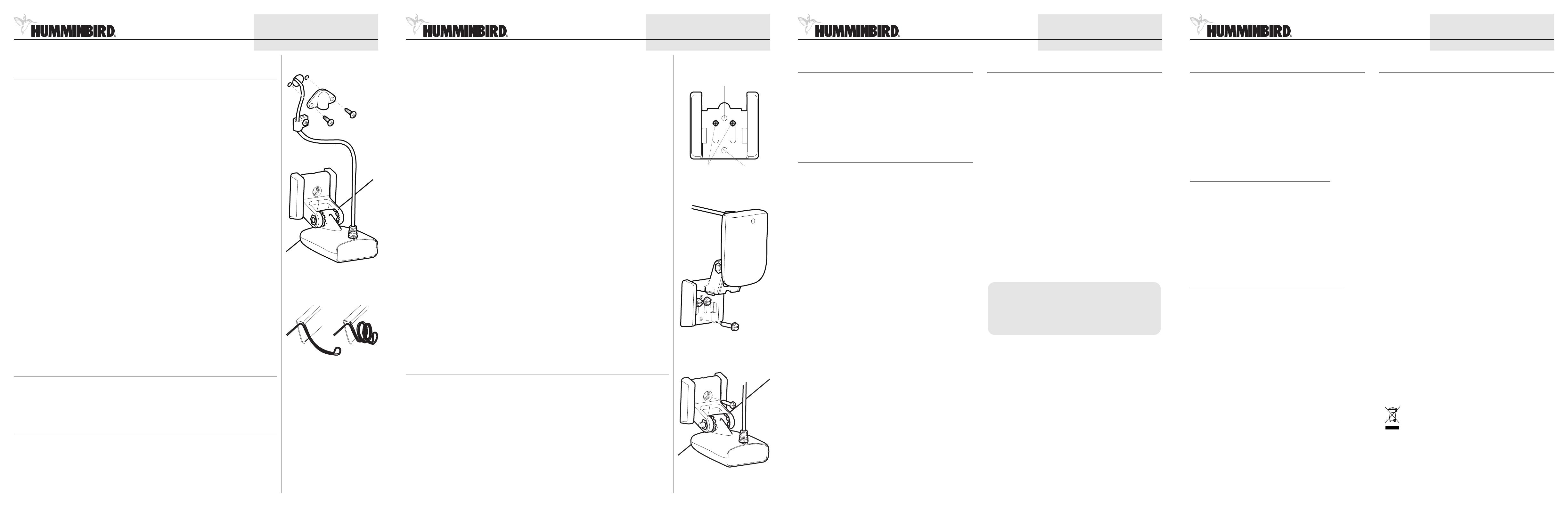
4.Routing the Cable
The transducer cable has a low profile connector, which must be routed to the point where the control head is
m
ounted. There are several ways to route the transducer cable to the area where the control head is installed. The
most common procedure routes the cable through the transom into the boat.
NOTE: Your boat may have a pre-existing wiring channel or conduit that you can use for the transducer cable.
1. Unplug the other end of the transducer cable from the control head. Make sure that the cable is long enough
to accommodate the planned route by running the cable over the transom.
CAUTION! Do not cut or shorten the transducer cable, and try not to damage the cable insulation. Route the
cable as far as possible from any VHF radio antenna cables or tachometer cables to reduce the possibility of
interference. If the cable is too short, extension cables are available to extend the transducer cable up to a total
of 50'. For assistance, contact the Customer Resource Center at www.humminbird.com or call 1-800-633-1468
for more information.
NOTE: The transducer can pivot up to 90 degrees in the bracket. Allow enough slack in the cable for this movement. It
is best to route the cable to the side of the transducer so the transducer will not damage the cable during movement.
2a. If you are routing the cable over the transom of the boat, secure the cable by attaching the cable clamp to
the transom, drilling 9/64" diameter holes for #8 x 5/8" wood screws, then skip directly to procedure 5,
Connecting the Cable.
or...
2b. If you will be routing the cable through a hole in the transom, drill a 5/8" diameter hole above the waterline.
Route the cable through this hole, then fill the hole with marine-grade silicone sealant and proceed to the
next step immediately.
3. Place the escutcheon plate over the cable hole and use it as a guide to mark the two escutcheon plate
mounting holes. Remove the plate, drill two 9/64" diameter x 5/8" deep holes, and then fill both holes with
marine-grade silicone sealant. Place the escutcheon plate over the cable hole and attach with two #8 x 5/8"
wood screws. Hand tighten only!
4. Route and secure the cable by attaching the cable clamp to the transom; drill one 9/64" diameter x 5/8" deep
hole, then fill hole with marine-grade silicone sealant, then attach the cable clamp using a #8 x 5/8" screw.
Hand tighten only!
NOTE: If there is excess cable that needs to be gathered at one location, dress the cable routed from both directions
so that a single loop is left extending from the storage location. Doubling the cable up from this point, form the cable
into a coil. Storing excess cable using this method can reduce electronic interference.
5.Connecting the Cable
Insert the transducer cable into the appropriate terminal slot. The cable connectors are labeled, and there are
corresponding labels on the cable holder on the rear of the control head. The slots are keyed to prevent reversed
installation, so be careful not to force the connector into the holder. Refer to your manual and/or control head
installation guide for the correct procedure for installing the cable connectors to the control head.
6.Test and Finish the Installation
Once you have installed both the control head and the transom transducer, and have routed all the cables, you
must perform a final test before locking the transducer in place. Testing should be performed with the boat in the
water, although you can initially confirm basic operation with the boat out of the water.
1. Press POWER once to turn the control head on. If the unit does not power up, make sure that the connector
holder is fully seated in the receptacle and that power is available.
2. If all connections are correct and power is available, the Humminbird® control head will enter Normal operation.
© 2008 Humminbird®, Eufaula AL, USA.
All rights reserved.
Storing Excess Cable
Routing the Cable


