Page is loading ...

INSTALLATION INSTRUCTIONS
FOR 4 POSITION CONDENSING SINGLE STAGE
GAS FURNACES WITH CONSTANT-TORQUE AIR
CIRCULATING BLOWER
(-)95T SERIES
U.L. and/or C.S.A. recognized fuel gas and CO (carbon monoxide) detectors are rec-
ommended in all applications, and their installation should be in accordance with the
manufacturer’s recommendations and/or local laws, rules, regulations, or customs.
92-24161-120-02
SUPERSEDES 92-24161-120-01
Factory Use Only
ISO 9001:2008

2
Contents
TABLE OF CONTENTS
1 TABLE OF CONTENTS. . . . . . . . . . . . . . . . . . . . . . . 2
2 GENERAL INFORMATION . . . . . . . . . . . . . . . . . . . . 3
Receiving . . . . . . . . . . . . . . . . . . . . . . . . . . . . . . . . . . 4
California Proposition 65 Note . . . . . . . . . . . . . . . . . . 4
Checklist . . . . . . . . . . . . . . . . . . . . . . . . . . . . . . . . . . . 5
3 SAFETY INFORMATION. . . . . . . . . . . . . . . . . . . . . . 6
Warnings. . . . . . . . . . . . . . . . . . . . . . . . . . . . . . . . . . . 6
Important Information About Efficiency and Quality. . 7
Commonwealth of Massachusetts Note . . . . . . . . . . 8
4 LOCATION REQUIREMENTS . . . . . . . . . . . . . . . . . 9
Freeze Protection . . . . . . . . . . . . . . . . . . . . . . . . . . . . 9
Site Selection . . . . . . . . . . . . . . . . . . . . . . . . . . . . . . 10
Clearance Accessibility. . . . . . . . . . . . . . . . . . . . . . . 10
Clearance Table . . . . . . . . . . . . . . . . . . . . . . . . . . . . 11
5 FIELD CONVERSION . . . . . . . . . . . . . . . . . . . . . . . 12
General Conversion Instructions and Tips. . . . . . . . 12
Lists of Materials for Parts Bag and
Conversion Kits. . . . . . . . . . . . . . . . . . . . . . . . . . . . 13
Conversion Table of Contents . . . . . . . . . . . . . . . . . 14
Upflow with Vertical Vent. . . . . . . . . . . . . . . . . . . 15-16
Upflow with Left Side Vent . . . . . . . . . . . . . . . . . 17-18
Downflow with Right Vent (Non Zero Clearance)
19-22
Downflow Zero-Clearance . . . . . . . . . . . . . . . . . 23-27
Horizontal Right with Right Vent . . . . . . . . . . . . . 29-30
Horizontal Right with Vertical Vent . . . . . . . . . . . 31-33
Horizontal Left with Right Vent . . . . . . . . . . . . . . 34-38
Horizontal Left with Left Vent . . . . . . . . . . . . . . . 39-41
6 DUCTING . . . . . . . . . . . . . . . . . . . . . . . . . . . . . . . . . 42
7 VENTING . . . . . . . . . . . . . . . . . . . . . . . . . . . . . . . . . 45
General Venting Requirements and Guidelines
(All Instructions) . . . . . . . . . . . . . . . . . . . . . . . . . . . . 45
Venting and Combustion Air Piping
Requirements . . . . . . . . . . . . . . . . . . . . . . . . . . . 45
Piping Requirements . . . . . . . . . . . . . . . . . . . . . . 46
Vent Pipe Sizing and Maximum Lengths . . . . . . . 48
Equivalent Vent Length. . . . . . . . . . . . . . . . . . . . . 49
Polypropylene Vent Products . . . . . . . . . . . . . . . . 50
Termination Requirements . . . . . . . . . . . . . . . . . . 51
Non-Direct Venting . . . . . . . . . . . . . . . . . . . . . . . . . 52
Non-Direct Venting in an Unconfined Space . . . . 52
Non-Direct Venting in a Confined Space . . . . . . . 52
Non-Direct Venting Termination . . . . . . . . . . . . . . 55
Non-Direct Venting Termination Clearances . . . . 57
Direct Venting . . . . . . . . . . . . . . . . . . . . . . . . . . . . . 58
Option 1: Standard Vertical Direct Vent
Termination . . . . . . . . . . . . . . . . . . . . . . . . . . . . 58
Option 2: Standard Horizontal Direct Vent
Termination . . . . . . . . . . . . . . . . . . . . . . . . . . . . 60
Option 3: Variant of Standard Horizontal
Direct Vent Termination . . . . . . . . . . . . . . . . . . . 60
Option 4: Alternate Horizontal Direct Vent
Termination . . . . . . . . . . . . . . . . . . . . . . . . . . . . 61
Option 5: Variant of Alternate Horizontal
Direct Vent Termination . . . . . . . . . . . . . . . . . . . 61
Optional Termination Angles for Alt.
Horizontal and Variant of Alt. Horizontal
Direct-Vent Terminations (Options 4 and 5) . . . 62
Option 6 & 7: Vertical and Horizontal
Concentric Vent Termination (RXGY-E02A and
RXGY-E03A) . . . . . . . . . . . . . . . . . . . . . . . . . . . 63
Option 8: Sidewall Vent Kit for Direct Vent
Termination (RXGY-G02) . . . . . . . . . . . . . . . . . 64
Direct Venting Termination Clearances . . . . . . . . 65
Multiventing of Direct Vent Furnaces . . . . . . . . . . 66
8 CONDENSATE DRAIN AND DRAIN
NEUTRALIZER . . . . . . . . . . . . . . . . . . . . . . . . . . 67
9 GAS SUPPLY AND PIPING . . . . . . . . . . . . . . . . . . 69
Gas Supply . . . . . . . . . . . . . . . . . . . . . . . . . . . . . . . . 69
Gas Piping . . . . . . . . . . . . . . . . . . . . . . . . . . . . . . . . 70
Gas Pressure . . . . . . . . . . . . . . . . . . . . . . . . . . . . . . 73
Gas Valve . . . . . . . . . . . . . . . . . . . . . . . . . . . . . . . . . 73
10 LP CONVERSION . . . . . . . . . . . . . . . . . . . . . . . . . . 74
Setting the Gas Pressure . . . . . . . . . . . . . . . . . . . . . 75
11 ELECTRICAL WIRING . . . . . . . . . . . . . . . . . . . . . . 76
Reversing the Electrical Connection . . . . . . . . . . . . 76
Thermostat . . . . . . . . . . . . . . . . . . . . . . . . . . . . . . . . 77
12 ACCESSORIES . . . . . . . . . . . . . . . . . . . . . . . . . . . . 78
Electronic Air Cleaner . . . . . . . . . . . . . . . . . . . . . . . . 78
Humidifier . . . . . . . . . . . . . . . . . . . . . . . . . . . . . . . . . 78
Filter . . . . . . . . . . . . . . . . . . . . . . . . . . . . . . . . . . . . . 78
13 TWINNING . . . . . . . . . . . . . . . . . . . . . . . . . . . . . . . . 80
14 HIGH ALTITUDE . . . . . . . . . . . . . . . . . . . . . . . . . . . 83
Natural Gas at High Altitudes . . . . . . . . . . . . . . . . . . 83
LP Gas at High Altitudes. . . . . . . . . . . . . . . . . . . . . . 85
15 STARTUP PROCEDURE . . . . . . . . . . . . . . . . . . . . 86
Sequence of Operations. . . . . . . . . . . . . . . . . . . . . . 86
16 DIAGNOSTICS AND FAULT CODES . . . . . . . . . . . 87
17 LOCKOUT . . . . . . . . . . . . . . . . . . . . . . . . . . . . . . . . 88
18 FIELD SELECTIONS – DIPSWITCHES. . . . . . . . . 89
19 FAULT CLEAR . . . . . . . . . . . . . . . . . . . . . . . . . . . . . 90
20 FAULT RECALL. . . . . . . . . . . . . . . . . . . . . . . . . . . . 90
21 FLAME STATUS L.E.D. . . . . . . . . . . . . . . . . . . . . . . 90
22 TIMING DIAGRAM. . . . . . . . . . . . . . . . . . . . . . . . . . 90
23 ADJUSTING OR CHECKING FURNACE INPUT . 91
24 SETTING INPUT RATE . . . . . . . . . . . . . . . . . . . . . . 91
25 AIRFLOW . . . . . . . . . . . . . . . . . . . . . . . . . . . . . . . . . 92
Blower Speed Selection . . . . . . . . . . . . . . . . . . . . . . 94
26 MAINTENANCE. . . . . . . . . . . . . . . . . . . . . . . . . . . . 95
27 SYSTEM OPERATION INFO . . . . . . . . . . . . . . . . . 96
28 ANNUAL INSPECTION . . . . . . . . . . . . . . . . . . . . . . 96
29 REPLACEMENT PARTS. . . . . . . . . . . . . . . . . . . . . 96
30 TROUBLESHOOTING. . . . . . . . . . . . . . . . . . . . . . . 96
Troubleshooting Guide . . . . . . . . . . . . . . . . . . . . . . . 97
31 WIRING DIAGRAM . . . . . . . . . . . . . . . . . . . . . . . . . 98

3
General Information
GENERAL INFORMATION
21
23
20
22
4
3
13
16
15
17
5
18
19
2
1
5
6
9
8
7
11
10
12
14
24
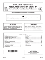
ITEM
NO. DESCRIPTION
1 CONDENSATE TRAP
2 DOOR SWITCH
3 JUNCTION BOX
4 TRANSFORMER
5 WATER SENSOR (2)
6 MAIN PRESSURE SWITCH
7 EXHAUST TRANSITION
8 COUPLING (ELBOW TO TRANSITION)
9 EXHAUST
10 SHIPPING PLUG
11 FLAME SENSOR
12 OVER TEMPERATURE SWITCH
13 TOP PLATE
14 BURNER
15 IGNITER
16 COMBUSTION AIR INLET
17 GAS VALVE
18 INDUCED DRAFT BLOWER (IDB)
19 CAPACITOR
20 CONTROL MOUNTING PLATE
21 BLOWER
22 LOW VOLTAGE TERMINAL
23 COUPLING (IDB TO ELBOW)
24 FURNACE CONTROL
ST-A1194-02-XO
FIGURE 1
FURNACE COMPONENTS
NOTE: A heat loss calculation must be performed to prop-
erly determine the required furnace BTU size for the struc-
ture. Also, the duct must be properly designed and
installed for proper airflow. Existing ductwork must be in-
spected for proper size and to make sure that it is properly
sealed. Proper airflow is necessary for both user comfort
and equipment performance.
Before opening the furnace carton, verify that the data
tags on the carton specify the furnace model number
that was ordered from the distributor and are correct for
the installation. If not, return the unit without opening the
carton. If the model number is correct, open the carton
and verify that the furnace rating label specifies the
same furnace model number that is specified on the car-
ton label. If the model numbers do not match, return the
furnace to the distributor.
IMPORTANT: Proper application, installation and mainte-
nance of this furnace and system is a must if consumers are
to receive the full benefits for which they have paid.
The (-)95T series furnaces are design-certified by CSA for
use with natural and propane gases as follows:
1. As non-direct vent central forced air furnaces taking
combustion air from the installation area or using air
ducted from the outside.
2. As direct vent central forced air furnaces with all com-
bustion air supplied directly to the furnace burners
through a special air intake system outlined in these in-
structions.Install this furnace in accordance with the
American National Standard Z223.1 – latest edition enti-
tled “National Fuel Gas Code” (NFPA54) and require-
ments or codes of the local utilities or other authorities
having jurisdiction. This is available from the following:
National Fire Protection Association, Inc.
Batterymarch Park
Quincy, MA 02269
CSA-INTERNATIONAL
8501 East Pleasant Valley Road
Cleveland, Ohio 44131-5575

4
In Canada installations must comply with CSA B149.1.
Install units in Canada in accordance with CSA-B149, local
installation codes and authorities having jurisdiction. CSA-
B149.1 is available from:
CSA INTERNATIONAL
5060 Spectrum Way
Mississauga, Ontario
Canada L4W 5N6
or www.csa.ca
NOTICE: Any equipment immersed in water (including by
flooding) must be replaced. Equipment and products im-
mersed in water will have operation adversely affected
thereby voiding the warranty.
RECEIVING
Immediately upon receipt, all cartons and contents should
be inspected for transit damage. Units with damaged car-
tons should be opened immediately. If damage is found, it
should be noted on the delivery papers, and a damage
claim filed with the last carrier.
• After unit has been delivered to job site, remove carton
taking care not to damage unit.
• Check the unit rating plate to be sure equipment
matches job specifications.
• Read the entire instructions before starting the installa-
tion.
• Install the unit in such a way as to allow necessary ac-
cess for service.
• Always remove the solid metal base pan from the top of
the furnace. The base pan is installed in this location for
shipping purposes only and should never remain in the
as-shipped location after installation.
• Install the unit with a 1/4” to 1/2” forward slope (toward
front) to ensure proper drainage.
• Install the unit in accordance with any local code which
may apply and the national codes. Latest editions are
available from: “National Fire Protection Association,
Inc., Batterymarch Park, Quincy, MA 02269.” These pub-
lications are:
• ANSI/NFPA No. 70-(Latest Edition) National Electrical
Code.
• NFPA90A Installation of Air Conditioning and Ventilating
Systems.
• NFPA90B Installation of warm air heating and air condi-
tioning systems.
• In Canada CSA 22.2 Canadian Electrical Code.
CALIFORNIA RESIDENTS ONLY
IMPORTANT: All manufacturer products meet current Fed-
eral OSHA Guidelines for safety. California Proposition 65
warnings are required for certain products, which are not
covered by the OSHA standards.
California's Proposition 65 requires warnings for products
sold in California that contain, or produce, any of over 600
listed chemicals known to the State of California to cause
cancer or birth defects such as fiberglass insulation, lead in
brass, and combustion products from natural gas.
All “new equipment” shipped for sale in California will have
labels stating that the product contains and/or produces
Proposition 65 chemicals. Although we have not changed
our processes, having the same label on all our products
facilitates manufacturing and shipping. We cannot always
know “when, or if” products will be sold in the California
market.
You may receive inquiries from customers about chemicals
found in, or produced by, some of our heating and air-con-
ditioning equipment, or found in natural gas used with some
of our products. Listed below are those chemicals and sub-
stances commonly associated with similar equipment in our
industry and other manufacturers.
• Glass Wool (Fiberglass) Insulation
• Carbon Monoxide (CO)
• Formaldehyde
• Benzene
More details are available at the Websites for OSHA (Occu-
pational Safety and Health Administration), at
www.osha.gov and the State of California's OEHHA (Office
of Environmental Health Hazard Assessment), at
www.oehha.org. Consumer education is important since the
chemicals and substances on the list are found in our daily
lives. Most consumers are aware that products present
safety and health risks, when improperly used, handled and
maintained.
General Information
GENERAL INFORMATION (cont.)

5
Installation Checklist
REFER TO INSTALLATION INSTRUCTIONS
GAS SUPPLY
______ Correct pipe size (record size)
______ Correct supply pressure (during furnace operation)
______ (record pressure)
______ Manifold pressure (record upstream pressure)
______ No gas leaks
______ L.P. Kit Number (if applicable) (record kit number)
ELECTRICAL
______ 115 V.A.C. supply (Dedicated Circuit)
(record voltage)
______ Polarity observed
______ Furnace properly grounded
______ Correct wire size (record type and gauge)
FURNACE INSTALLATION
______ Correct clearance to combustibles (record
______ clearance)
______ Correct clearance for service (at front) (record
______ clearance)
DUCT STATIC PRESSURE
______ in. w.c. on heating speed (record static pressure)
______ in. w.c. on cooling speed (record static pressure)
______ Air temperature rise in heat (record air temperature
______ rise)
______ Air temperature rise in cool (record air temperature
______ rise)
CONDENSATE LINE
______ Trap filled with water
______ Vented
______ Sloped toward drain
______ Condensate drain line hoses connected and
______ clamped
______ Freeze protection (if necessary)
VENTING – DIRECT VENT
______ in. diameter – intake pipe (record diameter)
______ in. diameter – exhaust pipe (record diameter)
______ ft. of pipe – intake air (record length)
______ no. of elbows – intake air (record number of
______ elbows)
______ ft. of pipe – exhaust pipe (record length)
______ no. of elbows – exhaust pipe (record number of
______ elbows)
______ Exhaust Vent Temperature (record temperature)
TERMINATIONS – DIRECT VENT
VERTICAL
______ Intake – 12" [305mm] min. above roof/snow level
(18" [457mm] in Canada) (record height above
anticipated snow level)
______ Correct relationship – exhaust to intake
HORIZONTAL/VERTICAL – CONCENTRIC (RXGY-E03A)
______ Intake – 12" [305mm] min. above roof/snow level
(18" [457mm] in Canada) (record height above
anticipated snow level)
______ Exhaust sloped down toward furnace
______ Correct distances (horizontal and vertical) –
exhaust to intake
______ 12" [305mm] min. above grade/snow level (18"
[457mm] in Canada) (record height above
anticipated snow level)
______ Above anticipated snow level (record maximum
______ anticipated snow level)
VENTING – NON-DIRECT VENT
______ in. diameter – exhaust pipe (record diameter)
______ ft. of pipe – exhaust (record length)
______ no. of elbows (record number of elbows)
TERMINATION – NON-DIRECT VENT
VERTICAL
______ 12" [305mm] min. above roof/snow level (18"
[457mm] in Canada) (record height above
anticipated snow level)
HORIZONTAL – STANDARD
______ 12" [305mm] min. above grade/snow level (18"
[457mm] in Canada) (record height above
anticipated snow level)
General Information
Installation Instructions remain with the furnace as a reference guide to the servicing contractor. We recommend
that performance and installation data be recorded for future reference on this sheet to meet service and warranty
obligations so that job site information is available when required.

6
Safety Information
!
WARNING
DO NOT INSTALL THIS FURNACE IN A MOBILE HOME!!
THIS FURNACE IS NOT APPROVED FOR INSTALLATION
IN A MOBILE HOME. DOING SO COULD CAUSE FIRE,
PROPERTY DAMAGE, PERSONAL INJURY OR DEATH.
!
WARNING
INSTALL THIS FURNACE ONLY IN A LOCATION AND PO-
SITION AS SPECIFIED IN THE LOCATION REQUIRE-
MENTS AND CONSIDERATIONS SECTION OF THESE
INSTRUCTIONS.
!
WARNING
IMPROPER INSTALLATION, OR INSTALLATION NOT
MADE IN ACCORDANCE WITH THE CSA INTERNATIONAL
(CSA) CERTIFICATION OR THESE INSTRUCTIONS, CAN
RESULT IN UNSATISFACTORY OPERATION AND/OR DAN-
GEROUS CONDITIONS AND ARE NOT COVERED BY THE
MANUFACTURER’S WARRANTY.
SAFETY INFORMATION
!
WARNING
DO NOT BYPASS, JUMPER, OR REMOVE ANY SAFETY
SWITCH FROM THE FURNACE CONTROL CIRCUIT. IF A
SAFETY SWITCH CAUSES THE FURNACE TO SHUT
DOWN OR OPERATE INTERMITTENTLY, IT IS AN INDICA-
TION OF A POTENTIAL SAFETY HAZARD THAT MUST BE
ADDRESSED BY A QUALIFIED TECHNICIAN, SERVICE
AGENCY OR THE GAS SUPPLIER. DO NOT RESET
SAFETY CONTROLS WITHOUT CORRECTIVE ACTION
AND/OR VERIFICATION OF PROPER SAFE OPERATION
BY A QUALIFIED INSTALLER, SERVICE AGENCY OR THE
GAS SUPPLIER.
REPLACE ANY SAFETY CONTROL COMPONENT ONLY
WITH IDENTICAL OEM REPLACEMENT PARTS. WHEN A
NEW SAFETY SWITCH IS INSTALLED, IT MUST BE
TESTED FOR A MINIMUM OF 15 MINUTES WITH THE
FURNACE OPERATING AT MAXIMUM INPUT RATE AND
WITH BOTH BLOWER AND BURNER DOOR INSTALLED.
IF THE FURNACE IS INSTALLED IN A CLOSET, THE
CLOSET DOOR MUST ALSO BE CLOSED FOR THIS
TEST. REPEAT THE TEST AT THE MINIMUM INPUT RATE
IF THE FURNACE IS A MULTI-STAGE FURNACE.
!
WARNING
USE ONLY WITH THE TYPE OF GAS APPROVED FOR
THIS FURNACE. REFER TO THE FURNACE RATING
PLATE.
!
WARNING
NEVER TEST FOR GAS LEAKS WITH AN OPEN FLAME.
USE A COMMERCIALLY AVAILABLE SOAP SOLUTION
MADE SPECIFICALLY FOR THE DETECTION OF LEAKS
TO CHECK ALL CONNECTIONS, AS SPECIFIED IN GAS
SUPPLY AND PIPING SECTION OF THESE INSTRUC-
TIONS.
!
WARNING
COMBUSTION AND VENTILATION AIR MUST BE PRO-
VIDED TO THE FURNACE AS REQUIRED BY THE NA-
TIONAL FUEL-GAS CODE (U.S.) AND CSA B149.1
(CANADA) AND THE COMBUSTION AND VENTILATION
AIR SECTION OF THESE INSTRUCTIONS.
!
WARNING
COMBUSTION PRODUCTS MUST BE DISCHARGED OUT-
DOORS. CONNECT THIS FURNACE TO AN APPROVED
VENT SYSTEM ONLY, AS SPECIFIED IN THE VENT PIPE
INSTALLATION SECTION OF THESE INSTRUCTIONS.
!
WARNING
WHEN A FURNACE IS INSTALLED SO THAT SUPPLY
DUCTS CARRY AIR CIRCULATED BY THE FURNACE TO
AREAS OUTSIDE THE SPACE CONTAINING THE FUR-
NACE, THE RETURN AIR SHALL ALSO BE HANDLED BY
DUCT(S) SEALED TO THE FURNACE CASING AND TERMI-
NATING OUTSIDE THE SPACE CONTAINING THE FUR-
NACE.
!
WARNING
WHENEVER THE FACTORY RETURN-AIR CONNECTION
IS NOT USED IT MUST BE SEALED. A SOLID METAL
BASE PLATE MUST BE INSTALLED AND SEALED. FAC-
TORY BASE PLATES ARE AVAILABLE AS ACCESSORY
ITEMS. (PART NUMBERS ARE LISTED IN THE SPEC
SHEET FOR THE FURNACE.) FAILURE TO INSTALL AND
SEAL THE BASE PLATE AND RETURN AIR DUCT CON-
NECTIONS MAY ALLOW CARBON MONOXIDE AND
OTHER CONTAMINANTS TO BE DRAWN INTO THE CON-
DITIONED AIR SPACE AND DISTRIBUTED THROUGHOUT
THE HEATED SPACE.
!
WARNING
DO NOT OPERATE THE SYSTEM WITHOUT FILTERS. A
PORTION OF THE DUST ENTRAINED IN THE AIR MAY
TEMPORARILY LODGE IN THE AIR DUCT RUNS AND AT
THE SUPPLY REGISTERS. ANY CIRCULATED DUST PAR-
TICLES WILL BE HEATED AND CHARRED BY CONTACT
WITH THE FURNACE HEAT EXCHANGER. THIS SOOTY
RESIDUE WILL SOIL CEILINGS, WALLS, DRAPES, CAR-
PETS AND OTHER HOUSEHOLD ARTICLES. SOOT DAM-
AGE MAY ALSO RESULT WITH, OR WITHOUT, FILTERS IN
PLACE, WHEN CERTAIN TYPES OF CANDLES ARE
BURNED, OR CANDLEWICKS ARE LEFT UNTRIMMED.
!
WARNING
IN COMPLIANCE WITH RECOGNIZED CODES, IT IS REC-
OMMENDED THAT AN AUXILIARY DRAIN PAN BE IN-
STALLED UNDER THIS FURNACE AND ANY INSTALLED
EVAPORATOR COIL THAT IS LOCATED IN ANY AREA OF
A STRUCTURE WHERE DAMAGE TO THE BUILDING OR
BUILDING CONTENTS MAY OCCUR AS A RESULT OF AN
OVERFLOW OF THE FURNACE CONDENSATE DISPOSAL
SYSTEM OR THE COIL DRAIN PAN OR A STOPPAGE IN
THE PRIMARY CONDENSATE DRAIN PIPING.

7
IMPORTANT INFORMATION
ABOUT EFFICIENCY AND
INDOOR AIR QUALITY
Central cooling and heating equipment is only as efficient
as the duct system that carries the cooled or heated air. To
maintain efficiency, comfort and good indoor air quality, it
is important to have the proper balance between the air
supplied to each room and the air returning to the cooling
and heating equipment.
Proper balance and sealing of the duct system improves
the efficiency of the heating and air conditioning system
and improves the indoor air quality of the home by reduc-
ing the amount of airborne pollutants that enter homes
from spaces where the ductwork and / or equipment is lo-
cated. The manufacturer and the U.S. Environmental Pro-
tection Agency’s Energy Star Program recommend that
central duct systems be checked by a qualified contractor
for proper balance and sealing.
Safety Information
SAFETY
!
WARNING
ALWAYS INSTALL THE FURNACE TO OPERATE WITHIN
THE FURNACE’S INTENDED TEMPERATURE-RISE
RANGE WITH A DUCT SYSTEM WHICH HAS AN EXTER-
NAL STATIC PRESSURE WITHIN THE ALLOWABLE
RANGE, AS SPECIFIED IN THE DUCTING SECTION OF
THESE INSTRUCTIONS. SEE ALSO FURNACE RATING
PLATE.
THE FURNACE MAY BE USED FOR HEATING OF BUILD-
INGS OR STRUCTURES UNDER CONSTRUCTION.
INSTALLATION MUST COMPLY WITH ALL INSTALLATION
INSTRUCTIONS INCLUDING:
PROPER VENT INSTALLATION;
-
FURNACE OPERATING UNDER THERMOSTAT-
CONTROL;
RETURN AIR DUCT SEALED TO THE FURNACE;
-
AIR FILTERS IN PLACE;-
SET FURNACE INPUT RATE AND TEMPERATURE-
RISE PER RATING PLATE MARKINGS;
MEANS FOR PROVIDING OUTDOOR AIR RE-
-
QUIRED FOR COMBUSTION;
RETURN AIR TEMPERATURE MAINTAINED BE-
-
TWEEN 55°F (13°C) AND 80°F (27°C); AND
CLEAN FURNACE, DUCT WORK AND COMPO-
-
NENTS UPON SUBSTANTIAL COMPLETION OF
THE CONSTRUCTION PROCESS, AND VERIFY
THAT THE FURNACE OPERATING CONDITIONS
INCLUDING IGNITION, INPUT RATE, TEMPERA-
TURE RISE AND VENTING, ACCORDING TO THE
INSTRUCTIONS AND CODES.
!
WARNING
DUCT LEAKS CAN CREATE AN UNBALANCED SYSTEM
AND DRAW POLLUTANTS SUCH AS DIRT, DUST, FUMES
AND ODORS INTO THE HOME CAUSING PROPERTY
DAMAGE. FUMES AND ODORS FROM TOXIC, VOLATILE
OR FLAMMABLE CHEMICALS, AS WELL AS AUTOMO-
BILE EXHAUST AND CARBON MONOXIDE (CO), CAN BE
DRAWN INTO THE LIVING SPACE THROUGH LEAKING
DUCTS AND UNBALANCED DUCT SYSTEMS CAUSING
PERSONAL INJURY OR DEATH (SEE FIGURE 2).
• IF AIR-MOVING EQUIPMENT OR DUCTWORK IS LO-
CATED IN GARAGES OR OFF-GARAGE STORAGE
AREAS - ALL JOINTS, SEAMS, AND OPENINGS IN THE
EQUIPMENT AND DUCT MUST BE SEALED TO LIMIT
THE MIGRATION OF TOXIC FUMES AND ODORS IN-
CLUDING CARBON MONOXIDE FROM MIGRATING
INTO THE LIVING SPACE.
• IF AIR-MOVING EQUIPMENT OR DUCTWORK IS LO-
CATED IN SPACES CONTAINING FUEL BURNING AP-
PLIANCES SUCH AS WATER HEATERS OR BOILERS -
ALL JOINTS, SEAMS, AND OPENINGS IN THE EQUIP-
MENT AND DUCT MUST ALSO BE SEALED TO PRE-
VENT DEPRESSURIZATION OF THE SPACE AND
POSSIBLE MIGRATION OF COMBUSTION BYPROD-
UCTS INCLUDING CARBON MONOXIDE INTO THE LIV-
ING SPACE.
FIGURE 2
MIGRATION OF DANGEROUS SUBSTANCES, FUMES, AND ODORS INTO
LIVING SPACES
Adapted from Residential Duct Diagnostics and Repair, with permission of Air Conditioning
Contractors of America (ACCA).

8
COMMONWEALTH OF MASSACHUSETTS NOTE
IMPORTANT! THE COMMONWEALTH OF MASSACHU-
SETTS REQUIRES COMPLIANCE WITH REGULATION
248 CMR 4.00 AND 5.00 FOR INSTALLATION OF
THROUGH-THE-WALL VENTED GAS APPLIANCES AS
FOLLOWS:
(a) For all side wall horizontally vented gas fueled equip-
ment installed in every dwelling, building or structure used
in whole or in part for residential purposes, including those
owned or operated by the Commonwealth and where the
side wall exhaust vent termination is less than seven (7)
feet above finished grade in the area of the venting, includ-
ing but not limited to decks and porches, the following re-
quirements shall be satisfied:
1. INSTALLATION OF CARBON MONOXIDE DETEC-
TORS. At the time of installation of the side wall horizontal
vented gas fueled equipment, the installing plumber or
gasfitter shall observe that a hard wired carbon monoxide
detector with an alarm and battery back-up is installed on
the floor level where the gas equipment is to be installed.
In addition, the installing plumber or gasfitter shall observe
that a battery operated or hard wired carbon monoxide de-
tector with an alarm is installed on each additional level of
the dwelling, building or structure served by the side wall
horizontal vented gas fueled equipment. It shall be the re-
sponsibility of the property owner to secure the services of
qualified licensed professionals for the installation of hard
wired carbon monoxide detectors.
a. In the event that the side wall horizontally vented gas fu-
eled equipment is installed in a crawl space or an attic, the
hard wired carbon monoxide detector with alarm and bat-
tery back-up may be installed on the next adjacent floor
level.
b. In the event that the requirements of this subdivision can
not be met at the time of completion of installation, the
owner shall have a period of thirty (30) days to comply with
the above requirements; provided, however, that during
said thirty (30) day period, a battery operated carbon
monoxide detector with an alarm shall be installed.
2. APPROVED CARBON MONOXIDE DETECTORS.
Each carbon monoxide detector as required in accordance
with the above provisions shall comply with NFPA 720 and
be ANSI/UL 2034 listed and IAS certified.
3. SIGNAGE. A metal or plastic identification plate shall be
permanently mounted to the exterior of the building at a
minimum height of eight (8) feet above grade directly in
line with the exhaust vent terminal for the horizontally
vented gas fueled heating appliance or equipment. The
sign shall read, in print size no less than one-half (1/2) inch
in size, “GAS VENT DIRECTLY BELOW. KEEP CLEAR
OF ALL OBSTRUCTIONS”.
4. INSPECTION. The state or local gas inspector of the
side wall horizontally vented gas fueled equipment shall
not approve the installation unless, upon inspection, the in-
spector observes carbon monoxide detectors and signage
installed in accordance with the provisions of 248 CMR
5.08(2)(a) 1 through 4.
(b) EXEMPTIONS: The following equipment is exempt
from 248 CMR 5.08(2)(a)1 through 4:
1. The equipment listed in Chapter 10 entitled “Equipment
Not Required To Be Vented” in the most current edition of
NFPA 54 as adopted by the Board; and
2. Product Approved side wall horizontally vented gas fu-
eled equipment installed in a room or structure separate
from the dwelling, building or structure used in whole or in
part for residential purposes.
(c) MANUFACTURER REQUIREMENTS – GAS EQUIP-
MENT VENTING SYSTEM PROVIDED. When the manu-
facturer of Product Approved side wall horizontally vented
gas equipment provides a venting system design or vent-
ing system components with the equipment, the instruc-
tions provided by the manufacturer for installation of the
equipment and the venting system shall include:
1. Detailed instructions for the installation of the venting
system design or the venting system components; and
2. A complete parts list for the venting system design or
venting system.
(d) MANUFACTURER REQUIREMENTS – GAS EQUIP-
MENT VENTING SYSTEM NOT PROVIDED. When the
manufacturer of a Product Approved side wall horizontally
vented gas fueled equipment does not provide the parts for
venting the flue gases, but identifies “special venting sys-
tems”, the following requirements shall be satisfied by the
manufacturer:
1. The referenced “special venting system” instructions
shall be included with the appliance or equipment installa-
tion instructions; and
2. The “special venting systems” shall be Product Ap-
proved by the Board, and the instructions for that system
shall include a parts list and detailed installation instruc-
tions.
(e) A copy of all installation instructions for all Product Ap-
proved side wall horizontally vented gas fueled equipment,
all venting instructions, all parts lists for venting instruc-
tions, and/or all venting design instructions shall remain
with the appliance or equipment at the completion of the
installation.
Safety Information

9
1. IMPORTANT: If installing the unit over a finished ceiling
or living area, be certain to install an auxiliary conden-
sate drain pan under the entire unit. This auxiliary drain
pan should extend under any evaporator coil installed
with the furnace and the open portion of the conden-
sate drain assembly. See “Condensate Drain/Neutral-
izer” section for more details.
2. IMPORTANT: If using a cooling evaporator coil with this
furnace, be sure the air passes over the heat ex-
changer before passing over the cooling coil. The
cooled air passing over the warm ambient air inside the
heat exchanger tubes can cause condensation inside
the tubes resulting in corrosion and eventual failure.
If these are manual dampers, they must be equipped to
prevent heating or cooling operation unless the damper is
in the full heat or cool position.
3. IMPORTANT: When the furnace is installed, there must
be 1/4” (minimum) to 1/2” (maximum) tilt at the back of
the unit as shown in Figure 3.
NOTE: These furnaces are approved for installation in at-
tics, as well as alcoves, utility rooms, closets and crawl-
spaces. Provisions must be made to prevent freezing of
condensate.
FREEZE PROTECTION
For installations where the furnace may reach temperatures
below 32°F (0°C) (such as an alcove or attic installation),
the installer must take precautions to ensure that the drain
trap and connected drain pipe do not freeze. Local codes
and practices should be followed in order to prevent freez-
ing.
If the drain trap is installed within the furnace cabinet, no
freeze protection is required. When the trap is mounted out-
side or partially outside the cabinet, it must be protected
from freezing. Regardless of the location of the drain trap,
any exposed drain piping must be protected from freezing
as required by local practices or codes. A UL or CSA listed
heat tape or UL or CSA approved heating cable with a rat-
ing of 3-6 watts per foot is acceptable protection when in-
stalled and maintained in accordance with the
manufacturer’s instructions. Good installation practices ne-
cessitate that the installer verify heat tape operation in ac-
cordance with the manufacturer’s instructions at the time of
installation.
IMPORTANT: Support this unit when installed. Since this
furnace is suitable for attic or crawl space installation, it
may be installed on combustible wood flooring or by using
support brackets.
FIGURE 3
1/4" MIN. TO 1/2" MAX. TILT
TOWARD THE FRONT
OF THE CABINET IN ALL
INSTALLATIONS AND
ORIENTATIONS
1/4" MIN. TO 1/2" MAX. TILT
TOWARD THE FRONT
OF THE CABINET IN ALL
INSTALLATIONS AND
ORIENTATIONS
UPFLOW / DOWNFLOW
HORIZONTAL (LEFT OR RIGHT)
ST-A1194-13-X0
LOCATION REQUIREMENTS
GENERAL INFORMATION
Location
!
WARNING
WHEN THIS FURNACE IS INSTALLED IN A RESI-
DENTIAL GARAGE, IT MUST BE INSTALLED SO THE
BURNERS AND IGNITION SOURCE ARE LOCATED
NO LESS THAN 18 INCHES [450MM] ABOVE THE
FLOOR. THIS IS TO PREVENT THE RISK OF IGNIT-
ING FLAMMABLE VAPORS WHICH MAY BE PRES-
ENT IN A GARAGE. ALSO, THE FURNACE MUST BE
LOCATED OR PROTECTED TO AVOID PHYSICAL
DAMAGE BY VEHICLES. FAILURE TO FOLLOW
THESE WARNINGS CAN CAUSE A FIRE OR EXPLO-
SION, RESULTING IN PROPERTY DAMAGE, PER-
SONAL INJURY OR DEATH.
LEVEL TO 1/2” MAX. TILT
TOWARD THE FRONT
OF THE CABINET IN ALL
INSTALLATIONS AND
ORIENTATIONS
LEVEL TO 1/2” MAX. TILT
TOWARD THE FRONT
OF THE CABINET IN ALL
INSTALLATIONS AND
ORIENTATIONS

10
Location
SITE SELECTION
1. Select a site in the building near the center of the pro-
posed, or existing, duct system.
2. Give consideration to the vent system piping when se-
lecting the furnace location. Be sure the venting system
can get from the furnace to the termination with minimal
length and elbows.
3. Locate the furnace near the existing gas piping. Or, if
running a new gas line, locate the furnace to minimize
the length and elbows in the gas piping. See Figure 5.
4. Locate the furnace to maintain proper clearance to
combustibles as shown in following Figure 6.
CLEARANCE – ACCESSIBILITY
The design of forced air furnaces with input ratings as
listed in the tables under Figure 6 are certified by CSA-In-
ternational for the clearances to combustible materials
shown in inches.
See name/rating plate and clearance label for specific
model number and clearance information.
Service clearance of at least 24 inches (30 cm) is recom-
mended in front of all furnaces.
NOTE: Use recommended 24” (30 cm) clearance if accessi-
bility clearances are greater than fire protection clearances.
For downflow non-zero clearance furnace installations, the
minimum clearance required on the right side of the fur-
nace is shown in Figure 4. If this clearance cannot be
maintained, a downflow zero-clearance kit; RXGY-ZK will
need to be installed.
GENERAL INFORMATION (cont.)
FIGURE 5
AIR FLOW
NOTE:
HORIZONTAL LEFT ORIENTATION DEPICTED IN ILLUSTRATION.
HORIZONTAL RIGHT ORIENTATION IS SIMILAR IN INSTALLATION.
ST-A1194-05-X0
FIGURE 4
OPTION - B
2” - 3” PIPE
OPTION - A
2” PIPE
8”
6”
ST-A1194-40-X0
CLEARANCE FLUE VENT TO WALL
!
WARNING
THIS FURNACE IS NOT APPROVED OR RECOM-
MENDED FOR INSTALLATION ON ITS BACK, WITH
ACCESS DOORS FACING UPWARDS.
!
WARNING
DO NOT LIFT THE UNIT BY THE HEAT EXCHANGER
TUBES. DOING SO CAN DAMAGE THE HEAT EX-
CHANGER ASSEMBLY.
!
WARNING
COMBUSTIBLE MATERIAL MUST NOT BE PLACED
ON OR AGAINST THE FURNACE JACKET. THE
AREA AROUND THE FURNACE MUST BE KEPT
CLEAR AND FREE OF ALL COMBUSTIBLE MATERI-
ALS INCLUDING GASOLINE AND OTHER FLAMMA-
BLE VAPORS AND LIQUIDS. PLACEMENT OF
COMBUSTIBLE MATERIALS ON, AGAINST OR
AROUND THE FURNACE JACKET CAN CAUSE AN
EXPLOSION OR FIRE RESULTING IN PROPERTY
DAMAGE, PERSONAL INJURY OR DEATH. THE
HOMEOWNER SHOULD BE CAUTIONED THAT THE
FURNACE AREA MUST NOT BE USED AS A
BROOM CLOSET OR FOR ANY OTHER STORAGE
PURPOSES.
!
WARNING
UPFLOW FURNACES ARE DESIGN-
CERTIFIED FOR
INSTALLATION ON COMBUSTIBLE FLOORS. NOTE,
HOWEVER, THAT FURNACES MUST NOT BE IN-
STALLED DIRECTLY ON CARPETING, TILE OR
OTHER COMBUSTIBLE MATERIAL OTHER THAN
WOOD FLOORING. INSTALLATION ON A COM-
BUSTIBLE MATERIAL CAN RESULT IN FIRE, CAUS-
ING PROPERTY DAMAGE, PERSONAL INJURY OR
DEATH.
LOCATION REQUIREMENTS
6” 8”
NOTE: These
dimensions refer
to furnace
clearance only.
For required
vent clearances
and supports,
refer to vent
manufacturer’s
instructions.

11
FIGURE 6
UNIT DIMENSIONS (CLEARANCE TO COMBUSTIBLES)
TOPBOTTOM
FRONTLEFT SIDE RIGHT SIDE
RIGHT BACK TOP FRONT VENT
(-)95TA-040
(-)95TA-060
(-)95TA-070
(-)95TA-085
(-)95TA-100
(-)95TA-115
0 0 0 1 2 0
0 0 0 1 2 0
0 0 0 1 2 0
0 0 0 1 2 0
0 0 0 1 2 0
0 0 0 1 2 0
SHIPPING
WEIGHTS
MINIMUM CLEARANCE (IN.)
MODEL
LEFT
SIDE
UNIT DIMENSIONS
(CLEARANCE TO COMBUSTIBLES)
A
I
R
F
L
O
W
A
B
.62
.62
34.00
23.33
25.44
26.19
22.63
25.81
26.31
8.00
11.03
17.50
18.13
26.11
29.05
32.65
24.19
22.31
OPTIONAL TRAP
LOCATION
(HORIZONTAL)
OPTIONAL CONDENSATE
DRAIN (DOWNFLOW)
GAS
CONNECTION
OPTIONAL COMBUSTION
VENT LOCATION
OPTIONAL TRAP
LOCATION
(HORIZONTAL)
OPTIONAL VENT
AIR INLET
CONDENSATE DRAIN
(UPFLOW)
ELECTRICAL CONNECTION
LINE VOLTAGE
ELECTRICAL CONNECTION
LOW VOLTAGE
22.96
23.80
8.00
11.00
17.44
29.05
26.17
32.88
23.00
14.00
28.06
1.12
29.62
.62
19.83
OPTIONAL LINE VOLTAGE
WIRING
OPTIONAL LOW VOLTAGE
WIRING
OPTIONAL CONDENSATE
DRAIN (UPFLOW)
TRAP LOCATION
(HORIZONTAL)
OPTIONAL
GAS CONNECTION
OPTIONAL
CONDENSATE DRAIN
(DOWNFLOW)
1.76
1.66
24.86
26.26
B
19.83
SUPPLY
AIR
23.21
1.62
1.67
24.91
.30
C
19.77
A
.65
RETURN
AIR
OPTIONAL
VENT OUTLET
KNOCKOUT
OPTIONAL COMBUSTION
AIR INLET KNOCKOUT
SSUUPPPPLLYY AANNDD RREETTUURRNN DDEEPPIICCTTEEDD AASS UUPPFFLLOOWW CCOONNFFIIGGUURRAATTIIOONN..
FFLLAANNGGEE CCOONNFFIIGGUURRAATTIIOONN WWIILLLL VVAARRYY DDEEPPEENNDDIINNGG OONN IINNSSTTAALLLLAATTIIOONN OORRIIEENNTTAATTIIOONN..
A
B C
17 1/2
16 17/64
16 13/64
21
19 49/64
19 45/64
24 1/2
23 17/64
23 13/64
FLANGE DIMENSIONS
125
*A SERVICE CLEARANCE OF AT LEAST 24” IS RECOMMENDED IN FRONT OF ALL FURNACES
ST-A1194-01-X0
Location

12
Field Conversions
FIELD CONVERSIONS
CONDENSATE PVC/HOSE OPTIONS
BULKHEAD COUPLING
CONDENSATE DRAINAGE HAS OPTIONS FOR 3/4" OR 1/2"
PVC CONNECTIONS. THE BULKHEAD COUPLING CONNECTS THE
RUBBER HOSES FROM INSIDE THE UNIT TO THE PVC PIPE
EXTERIOR OF THE UNIT. PVC PIPE CAN BE CEMENTED
DIRECTLY TO THE COUPLING AND THE TRAP WITH PROPER
PVC CEMENT AND PRIMER.
1/2" PVC
PIPE
3/4" PVC
TEE
RUBBER HOSE
CONNECTION
PVC FITTING/PIPE
3/4" PVC
COUPLING
IN ADDITION TO PVC CONNECTIONS, THE CONDENSATE
TRAP CAN ACCOMODATE A 5/8" RUBBER HOSE WITH A
HOSE CLAMP WHEN LOCATED INSIDE THE UNIT.
NOTE: IMPROPER HOSE CONNECTIONS WILL PREVENT
CONDENSATE FROM DRAINING AND MAY DAMAGE FURNACE.
CONDENSATE TRAP
THE CONDENSATE TRAP HAS 2 SIDES PLEASE NOTE THEIR
LOCATIONS FOR DRAIN CONNECTIONS DURING CONVERSION.
OUT TO DRAIN
COLLECTOR BOX
IN FROM
IN FROM FLUE
ELBOW OR COUPLING
1/4" VENT IN
FROM COLLECTOR BOX
GENERAL CONVERSION INSTRUCTIONS
ST-A1194-37-X0
-2010°
CONVERSION AND INSTALLATION
CONSIDERATIONS
ALL CONVERSIONS REQUIRE THE CONDENSATE PLUMBING TO
HAVE DECLINE IN THE DIRECTION OF THE WATER FLOW.
WHEN INSTALLING AND MOVING CONDENSATE PLUMBING THE
HOSES SHOULD BE FREE OF KINKS FOR PROPER WATER FLOW.
WHEN DRAIN HOSE OR CONDENSATE TRAP HOSE
ROUTING CHANGES ARE NECESSARY BE SURE TO PLUG OR CAP
ANY UNUSED HOSE TAPS.
THE INDUCER COUPLING COMES FROM THE FACTORY WITH
A 10
TILT FOR UP FLOW INSTALLATIONS. WHEN
CONVERTED TO DOWN FLOW THE COUPLING REQUIRES A
ROTATION A MINIMUM OF 10
FROM HORIZONTAL AS SHOWN.
HORIZONTAL INSTALLATIONS REQUIRE CONDENSATE TRAP TO BE
MOUNTED EXTERNALLY BELOW THE UNIT:
-USE CAUTION: MOUNT THE TRAP AFTER THE UNIT IS AT
THE POINT OF INSTALLATION TO PREVENT DAMAGE TO THE
TRAP DURING TRANSPORT.
-HAND TIGHTEN SCREWS WHEN MOUNTING THE TRAP OR THE
BULKHEAD COUPLING TO THE CABINET TO PREVENT DAMAGE
TO THE MOUNTING FLANGE.
-USE PROPER FREEZE PROTECTION IF REQUIRED.
-ALLOW MINIMUM OF 6" BELOW THE FURNACE FOR CLEARANCE.
10-20°
TILT ON INDUCER COUPLING
GROUND
GROUND
LEVEL
MIDLINE
WORM
DRIVE
CLAMP
COUPLING
THE WORM DRIVE FOR THE HOSE CLAMPS
USED ON THE FLUE TRANSITION COUPLING
OR THE IDB COUPLING MUST BE ABOVE THE
LEVEL MIDLINE WHEN IN THE HORIZONTAL
POSITION AS DETAILED HERE.
IF THE IDB COUPLING IS REMOVED, IT MUST BE REPLACED IN THE
PROPER ORIENTATION. AN ARROW IS PRESENT ON THE COUPLING
TO INDICATE THE DIRECTION OF EXHAUST FLOW. MAKE SURE THE
ARROW POINTS IN THE CORRECT DIRECTION.
NOTE:
HORIZONTAL INSTALLATIONS REQUIRE CONDENSATE TRAP
TO BE MOUNTED EXTERNALLY BELOW THE UNIT:

13
FIELD CONVERSIONS
Field Conversions
PARTS BAG(PROVIDED WITH UNIT)
CONVERSION KIT RXGY-CK
CONVERSION KIT RXGY-ZK
(X2)
2-5/8" FLUSH
MOUNT PLUG
1/2" DRAIN
HOSE E
INTAKE
COUPLING
.559" CONDENSATE
TRAP DRAIN PLUG
#8 X 1/2"
SCREW
(X2)
INTAKE
PIPE
1/4" BLACK
VENT TUBE
BULKHEAD
COUPLING
ALTERNATE DRAIN ASSEMBLY
TUBE C
HOSE CLAMP
INTAKE AIR
DIFFUSER
#8 X 1/2"
SCREW
(X4)
#8 X 1/2"
SCREW
(X10)
5/8" DRAIN
HOSE B
CONDENSATE TRAP
BRACKET (DOWN FLOW)
2" PVC VANE
1/4" HOLE
PLUG
1/2" DRAIN
HOSE F
1/2" DRAIN
HOSE G
CONDENSATE
TRAP GASKET
2" PIPE GROMMET
(
3.375)
1/2" VINYL
CAP (YELLOW)
PIPE COLLAR
GASKET ASSEMBLY
(X2)
ST-A1194-38-01
GENERAL PARTS REQUIRED FOR CONVERSIONS
(X2)
FLUE PIPE
ASSEMBLY
W/ O-RING
O-RING
SEE NEXT PAGE FOR APPLICABLE CONFIGURATIONS

14
Field Conversions
FIELD CONVERSIONS
LISTS OF MATERIALS FOR PARTS BAGS AND CONVERSION KITS. . . . . . . . . . . . . . . . . . . . . . . . . . . . . . . . . . . . . . . . Pg 12
GENERAL CONVERSION INSTRUCTIONS AND TIPS . . . . . . . . . . . . . . . . . . . . . . . . . . . . . . . . . . . . . . . . . . . . . . . . . . Pg 13
UPFLOW WITH VERTICAL VENT . . . . . . . . . . . . . . . . . . . . . . . . . . . . . . . . . . . . . . . . . . . . . . . . . . . . . . . . . . . . . . . Pg 15-16
UPFLOW WITH LEFT SIDE VENT. . . . . . . . . . . . . . . . . . . . . . . . . . . . . . . . . . . . . . . . . . . . . . . . . . . . . . . . . . . . . . . Pg 17-18
DOWNFLOW WITH RIGHT VENT (NON-ZERO CLEARANCE). . . . . . . . . . . . . . . . . . . . . . . . . . . . . . . . . . . . . . . . . Pg 19-22
DOWNFLOW ZERO-CLEARANCE . . . . . . . . . . . . . . . . . . . . . . . . . . . . . . . . . . . . . . . . . . . . . . . . . . . . . . . . . . . . . . Pg 23-27
HORIZONTAL RIGHT WITH RIGHT VENT . . . . . . . . . . . . . . . . . . . . . . . . . . . . . . . . . . . . . . . . . . . . . . . . . . . . . . . . Pg 28-30
HORIZONTAL RIGHT WITH VERTICAL VENT . . . . . . . . . . . . . . . . . . . . . . . . . . . . . . . . . . . . . . . . . . . . . . . . . . . . . Pg 31-33
HORIZONTAL LEFT WITH RIGHT VENT. . . . . . . . . . . . . . . . . . . . . . . . . . . . . . . . . . . . . . . . . . . . . . . . . . . . . . . . . . Pg 34-38
HORIZONTAL LEFT WITH LEFT VENT . . . . . . . . . . . . . . . . . . . . . . . . . . . . . . . . . . . . . . . . . . . . . . . . . . . . . . . . . . . Pg 39-41
FIELD CONVERSION TO VARIOUS CONFIGURATIONS
Furnaces can be converted in the field from upflow (as-shipped) to downflow, horizontal left or horizontal right as necessary.
In addition, there are different venting options, including a zero-clearance option, to give the installer flexibility in locating the
venting for this furnace.
AIRFLOW
AIRFLOW
AIRFLOW
AIRFLOW
(REQUIRES CONVERSION
KIT RXGY-CK)
(REQUIRES CONVERSION
KIT RXGY-CK)
(REQUIRES CONVERSION
KIT RXGY-CK AND ZERO-
CLEARANCE KIT RXGY-ZK)
(REQUIRES CONVERSION
KIT RXGY-CK)
(REQUIRES CONVERSION
KIT RXGY-CK)
(REQUIRES CONVERSION
KIT RXGY-CK AND ZERO-
CLEARANCE KIT RXGY-ZK)
(REQUIRES CONVERSION
KIT RXGY-CK)
AIRFLOW
AIRFLOW
AIRFLOW
AIRFLOW

15
Field Conversions
TUBE C
CUT TO FIT
CABINET WIDTH
4b2
4b3
4b1
NOTE:
USE SOAPY WATER TO FACILITATE EASY
HOSE AND TUBE ASSEMBLY
4B
4b - RIGHT SIDE DRAIN OPTION
4b1 - CUT TUBE C TO FIT CORRESPONDING CABINET WIDTH.
4b2 - INSTALL TUBE C WITH HOSE CLAMP AS SHOWN TO HOSE A (PRE-INSTALLED).
4b3 - ATTACH TUBE C ASSEMBLY TO BULKHEAD COUPLING AS SHOWN.
4b4 - INSTALL HOSE CLAMP OVER HOSE ON BULKHEAD COUPLING.
HOSE A
TUBE C
NOTE:
USE SOAPY WATER TO FACILITATE EASY
HOSE AND TUBE ASSEMBLY
4A
HOSE A
4a - LEFT SIDE DRAIN OPTION
ATTACH HOSE A (PRE-INSTALLED) TO BULKHEAD COUPLING.
INSTALL HOSE CLAMP ON HOSE OVER BULK HEAD COUPLING.
3
INSTALL BULKHEAD COUPLING USING (2) SCREWS.
INSTALL IN JACKET WITH THE BARBED FITTING
POINTED INTO THE VESTIBULE.
INSTALL
2
OPTION DRAIN RIGHT
DETERMINE RIGHT OR LEFT DRAIN OPTION.
LOCATE 7/8" HOLE IN JACKET SIDE.
REMOVE PLUG - DISCARD.
DRILL (2) Ø 1/8" HOLES FOR THE BULKHEAD COUPLING.
DRILL 1/8”
DRILL 1/8”
7/8” PLUG
DISCARD
OPTION DRAIN LEFT
7/8” PLUG
DISCARD
1
INSTALL INTAKE COUPLING IN TOP PLATE.
INSTALL
UPFLOW VERTICAL VENT
NOTE: THESE CONVERSION INSTRUCTIONS ARE INTENTIONALLY GENERIC, SOME PARTS MAY BE DIFFERENT IN YOUR FURNACE
ST-A1194-28-01
PARTS NEEDED:
PARTS NEEDED FOR THIS CONVERSION REQUIRE ITEMS
FROM THE PARTS BAG ONLY. NO OTHER CONVERSION
KITS ARE NEEDED.
!
TUBE C
BULKHEAD
COUPLING
FROM PARTS BAG (PROVIDED WITH UNIT)
(X2)
#8 X 1/2"
SCREW
HOSE
CLAMP
INTAKE
COUPLING
W/ NUT
ELECTRIC DRILL
1/8" DRILL BIT
PLIERS
1/4" HEX HEAD DRIVER
TUBING CUTTER
TOOLS/MATERIALS NEEDED:
(X2)
(X2)
4b4

16
Field Conversions
ST-A1194-28-01
Notes:
Checklist:
__ ALL DRAIN PORTS ARE PLUGGED
__ UNIT HAS FORWARD PITCH
__ HEAT TAPE INSTALLED(IF REQUIRED)
__ VERIFY ALL HOSES ARE SECURE AND FULLY SEATED.
__ CONFIRM THAT ALL HOSES ARE FREE OF KINKS
__ CONFIRM ALL HOSES AND OTHER DRAIN PARTS HAVE A
SLOPE IN DIRECTION OF WATER FLOW
__ ALL CLAMPS AND COUPLINGS ARE TIGHTENED

17
Field Conversions
ELECTRIC DRILL
1/8" DRILL BIT
PLIERS
FLAT HEAD SCREWDRIVER
5/16 HEX HEAD DRIVER
1/4" HEX HEAD DRIVER
TUBING CUTTER
TOOLS/MATERIALS NEEDED:
UPFLOW LEFT VENT
NOTE: THESE CONVERSION INSTRUCTIONS ARE INTENTIONALLY GENERIC, SOME PARTS MAY BE DIFFERENT IN YOUR FURNACE
ST-A1194-29-01
PARTS NEEDED:
(X2)
FROM PARTS BAG (PROVIDED W/UNIT)
INTAKE
COUPLING
W/ NUT
BULKHEAD
COUPLING
#8 X 1/2"
SCREW
TUBE C
HOSE
CLAMP
4
INSTALL BULKHEAD COUPLING USING (2) SCREWS.
INSTALL IN JACKET WITH THE BARBED FITTING
POINTED INTO THE VESTIBULE.
3
DETERMINE RIGHT OR LEFT DRAIN OPTION.
LOCATE 7/8" HOLE IN JACKET SIDE.
REMOVE PLUG - DISCARD.
DRILL (2)
ø1/8" HOLES FOR THE BULKHEAD COUPLING.
DRILL 1/8”
DISCARD
OPTION DRAIN RIGHT
DRILL 1/8”
DISCARD
OPTION DRAIN LEFT
2
2a - INSTALL 2-5/8" FLUSH MOUNT PLUG IN TOP PLATE.
2b - INSTALL 2" PIPE GROMMET AS SHOWN.
2c - INSTALL INTAKE COUPLING AS SHOWN.
2b
2c
2a
2-5/8”
1a
1b
1c
1
1a - REMOVE FLUE TRANSITION, TRANSITION COUPLING, AND ELBOW.
(NOTE: REMOVE INDUCER COUPLING W/ELBOW FOR EASIER REMOVAL).
1b - REMOVE 3-3/8" FLUSH MOUNT PLUG FROM JACKET - DISCARD.
1c - RELOCATE 2-3/8" FLUSH MOUNT PLUG FROM JACKET TO TOP PLATE.
RE-LOCATE
DISCARD
IDB COUPLING
(RETAIN)
FLUE TRANSITION
(DISCARD)
TRANSITION
COUPLING
(DISCARD)
ELBOW
(DISCARD)
FROM CONVERSION KIT RXGY-CK
2-3/8" PIPE
GROMMET
2-5/8" FLUSH
MOUNT PLUG
PARTS NEEDED FOR THIS
CONVERSION REQUIRE THE
OUTLINED ITEMS FROM THE PARTS BAG
AND CONVERSION KIT RXGY-CK. YOU
MUST HAVE THESE PARTS BEFORE
PROCEEDING.
!
IF THE IDB
COUPLING IS
REMOVED, IT
MUST BE
REPLACED IN
THE PROPER
ORIENTATION.
AN ARROW IS
PRESENT ON
THE COUPLING
TO INDICATE
THE DIRECTION
OF EXHAUST
FLOW. MAKE
SURE THE
ARROW POINTS
IN THE
CORRECT
DIRECTION.
NOTE:
(X2)
SEE CRITICAL HOSE CLAMP LOCATION NOTE
IN THE GENERAL COVERSION INSTRUCTIONS.

18
Field Conversions
(X2)
5B
5b - RIGHT SIDE DRAIN OPTION
5b1 - CUT TUBE C TO FIT CORRESPONDING CABINET WIDTH.
5b2 - INSTALL TUBE C WITH HOSE CLAMP AS SHOWN TO HOSE A (PRE-INSTALLED).
5b3 - ATTACH TUBE C ASSEMBLY TO BULKHEAD COUPLING AS SHOWN.
5b4 - INSTALL HOSE CLAMP OVER HOSE ON BULKHEAD COUPLING.
HOSE A
TUBE C
TUBE C
CUT TO FIT
CABINET WIDTH
5b2
5b3
5b1
NOTE:
USE SOAPY WATER TO FACILITATE EASY
HOSE AND TUBE ASSEMBLY
5A
HOSE A
5a - LEFT SIDE DRAIN OPTION
ATTACH HOSE A (PRE-INSTALLED) TO BULKHEAD COUPLING.
PLACE CLAMP OVER HOSE ON BULKHEAD COUPLING.
NOTE:
USE SOAPY WATER TO FACILITATE EASY
HOSE AND TUBE ASSEMBLY
Checklist:
ST-A1194-29-01
Notes:
__ VERIFY ALL HOSES ARE SECURE AND FULLY SEATED.
__ CONFIRM THAT ALL HOSES ARE FREE OF KINKS.
__ CONFIRM ALL HOSES AND OTHER DRAIN PARTS HAVE A
SLOPE IN DIRECTION OF WATER FLOW
__ BOTH WORM DRIVES ON THE HOSE CLAMPS OF THE IDB COUPLING
MUST BE LOCATED ON THE TOP OF THE COUPLING. SEE LOCATION
DETAIL IN THE GENERAL CONVERSION INSTRUCTIONS AT THE
BEGINNING OF THIS SECTION.
__ ALL CLAMPS AND COUPLINGS ARE TIGHTENED
__ ALL DRAIN PORTS ARE PLUGGED
__ UNIT HAS FORWARD PITCH
__ HEAT TAPE INSTALLED(IF REQUIRED)

19
Field Conversions
DOWNFLOW W/ RIGHT VENT (NON-ZERO CLEARANCE)
DOWNFLOW W/ RIGHT VENT (NON-ZERO CLEARANCE)
PARTS NEEDED FOR THIS CONVERSION REQUIRE ITEMS
DOWNFLOW W/ RIGHT VENT (NON-ZERO CLEARANCE)
PARTS NEEDED FOR THIS CONVERSION REQUIRE ITEMS
DOWNFLOW W/ RIGHT VENT (NON-ZERO CLEARANCE)
PARTS NEEDED FOR THIS CONVERSION REQUIRE ITEMS
DOWNFLOW W/ RIGHT VENT (NON-ZERO CLEARANCE)
PARTS NEEDED:
(X2)
FROM PARTS BAG (PROVIDED WITH UNIT)
(X2)
FROM THE
YOU MUST HAVE THE PARTS OUTLINED BELOW BEFORE
PROCEEDING.
!
PARTS NEEDED:
FROM PARTS BAG (PROVIDED WITH UNIT)
FROM THE PARTS BAG AND CONVERSION KIT
YOU MUST HAVE THE PARTS OUTLINED BELOW BEFORE
PROCEEDING.
AND CONVERSION KIT RXGY-CK.
YOU MUST HAVE THE PARTS OUTLINED BELOW BEFORE
FROM CONVERSION KIT RXGY-CK
2-5/8" FLUSH
2" PIPE GROMMET
#8 X 1/2"
SCREW
HOSE
CLAMP
FROM CONVERSION KIT RXGY-CK
2-5/8" FLUSH
#8 X 1/2"
SCREW
(X4)
ALTERNATE DRAIN ASSEMBLY
TUBE C
CONDENSATE
TRAP DRAIN
PLUG .559”
COUPLING
ALTERNATE DRAIN ASSEMBLY
INTAKE AIR
DIFFUSER
CONDENSATE
TRAP BRACKET
INTAKE
COUPLING
W/ NUT
BULKHEAD
COUPLING
1/4" BLACK
CONDENSATE
TRAP BRACKET
NOTE: STEPS 1- 5 SHOWN WITH FURNACE IN “AS SHIPPED CONFIGURATION”
NOTE: THESE CONVERSION INSTRUCTIONS ARE INTENTIONALLY GENERIC, SOME PARTS MAY BE DIFFERENT IN YOUR FURNACE
ELECTRIC DRILL
(1) 1/8" DRILL BIT
TOOLS/MATERIALS NEEDED:
2-5/8" FLUSH
MOUNT PLUG
(
3.375)
NOTE: STEPS 1- 5 SHOWN WITH FURNACE IN “AS SHIPPED CONFIGURATION”
NOTE: THESE CONVERSION INSTRUCTIONS ARE INTENTIONALLY GENERIC, SOME PARTS MAY BE DIFFERENT IN YOUR FURNACE
(1) 3/16" DRILL BIT
PLIERS
TOOLS/MATERIALS NEEDED:
2-5/8" FLUSH
MOUNT PLUG
NOTE: STEPS 1- 5 SHOWN WITH FURNACE IN “AS SHIPPED CONFIGURATION”
NOTE: THESE CONVERSION INSTRUCTIONS ARE INTENTIONALLY GENERIC, SOME PARTS MAY BE DIFFERENT IN YOUR FURNACE
(1) 1/4" HEX HEAD DRIVER
(1) 5/16 HEX HEAD DRIVER
TOOLS/MATERIALS NEEDED:
5/8" DRAIN
HOSE B
NOTE: THESE CONVERSION INSTRUCTIONS ARE INTENTIONALLY GENERIC, SOME PARTS MAY BE DIFFERENT IN YOUR FURNACE
FLAT HEAD SCREWDRIVER
TUBE CUTTER
TRAP BRACKET
(DOWN FLOW)
1/2" DRAIN
HOSE E
NOTE: THESE CONVERSION INSTRUCTIONS ARE INTENTIONALLY GENERIC, SOME PARTS MAY BE DIFFERENT IN YOUR FURNACE
FLAT HEAD SCREWDRIVER
1/4" BLACK
VENT TUBE
TRAP BRACKET
(DOWN FLOW)
1
1a
TRANSITION
COUPLING
(DISCARD)
FLUE TRANSITION (DISCARD)
ELBOW (DISCARD)
IDB COUPLING
(RETAIN)
2
2-5/8"
TRANSITION
COUPLING
(DISCARD)
FLUE TRANSITION (DISCARD)
ELBOW (DISCARD)
IDB COUPLING
(RETAIN)
2d
2-5/8"
INSTALL
1b
VENT HOSE
(DISCARD)
HOSE “D”
(RETAIN)
DISCARD
2a
VENT HOSE
(DISCARD)
HOSE “D”
(RETAIN)
IF THE IDB COUPLING IS
REMOVED, IT MUST BE
REPLACED IN THE PROPER
ORIENTATION. AN ARROW IS
PRESENT ON THE COUPLING
TO INDICATE THE DIREC-
NOTE:
M
O
O
V
M
V
E
O
E
V
2c
IF THE IDB COUPLING IS
REMOVED, IT MUST BE
REPLACED IN THE PROPER
ORIENTATION. AN ARROW IS
PRESENT ON THE COUPLING
TO INDICATE THE DIREC-
M
O
V
E
2b
1a - REMOVE FLUE TRANSITION, TRANSITION COUPLING, AND ELBOW.
(NOTE: REMOVE COUPLING ON INDUCER WITH ELBOW FOR EASIER REMOVAL)
1b - REMOVE TRAP AND HOSES. RETAIN HOSE D FOR LATER USE.
(NOTE:TO REMOVE TRAP REMOVE (2) SCREWS AND PULL STRAIGHT OUT).
1a - REMOVE FLUE TRANSITION, TRANSITION COUPLING, AND ELBOW.
(NOTE: REMOVE COUPLING ON INDUCER WITH ELBOW FOR EASIER REMOVAL)
1b - REMOVE TRAP AND HOSES. RETAIN HOSE D FOR LATER USE.
(NOTE:TO REMOVE TRAP REMOVE (2) SCREWS AND PULL STRAIGHT OUT).
2a-REMOVE 3-3/8" FLUSH MOUNT PLUG FROM JACKET - DISCARD.
2b-RELOCATE 2-3/8" FLUSH MOUNT PLUG FROM JACKET TO TOP PLATE.
2c-RELOCATE 1/2" VINYL CAP (YELLOW) IN INDUCER COUPLING.
2d-INSTALL 2-5/8" FLUSH PLUG IN TOP PLATE.
1a - REMOVE FLUE TRANSITION, TRANSITION COUPLING, AND ELBOW.
(NOTE: REMOVE COUPLING ON INDUCER WITH ELBOW FOR EASIER REMOVAL).
1b - REMOVE TRAP AND HOSES. RETAIN HOSE D FOR LATER USE.
(NOTE:TO REMOVE TRAP REMOVE (2) SCREWS AND PULL STRAIGHT OUT).
TION OF EXHAUST FLOW.
MAKE SURE THE ARROW
POINTS IN THE CORRECT
DIRECTION.
2a-REMOVE 3-3/8" FLUSH MOUNT PLUG FROM JACKET - DISCARD.
2b-RELOCATE 2-3/8" FLUSH MOUNT PLUG FROM JACKET TO TOP PLATE.
2c-RELOCATE 1/2" VINYL CAP (YELLOW) IN INDUCER COUPLING.
2d-INSTALL 2-5/8" FLUSH PLUG IN TOP PLATE.
TION OF EXHAUST FLOW.
MAKE SURE THE ARROW
POINTS IN THE CORRECT
ST-A1194-30-X0
2a-REMOVE 3-3/8" FLUSH MOUNT PLUG FROM JACKET - DISCARD.
2b-RELOCATE 2-3/8" FLUSH MOUNT PLUG FROM JACKET TO TOP PLATE.
2c-RELOCATE 1/2" VINYL CAP (YELLOW) IN INDUCER COUPLING.

20
Field Conversions
ST-A1194-30-X0
ROTATE
UNIT
5b
5a
5a - PRE-DRILL (2) Ø 3/16" HOLES IN JACKET AS SHOWN FOR CONDENSATE TRAP BRACKET.
5b - ROTATE UNIT 180°
DRILL (2)
Ø3/16" HOLES
5
.559
DRAIN PLUG
4c
4a
4b
DISCARD
4a - REMOVE THE SMALL MOUNTING BRACKET AND THE .403"
DRAIN PLUG - DISCARD.
4b - INSTALL THE DOWN FLOW CONDENSATE TRAP BRACKET WITH
(2) SCREWS AS SHOWN.
4c - INSTALL .559" DRAIN PLUG IN THE CONDENSATE TRAP.
4
3d
3c
3a
3b
3a - RELOCATE .403" DRAIN PLUG IN THE COLLECTOR BOX.
3b - INSTALL 2" PIPE GROMMET
3c - INTAKE COUPLING IN JACKET AS SHOWN.
3d - INSERT AIR DIFFUSER INTO COUPLING UNTIL TABS ARE SEATED.
3
INSERT AIR
DIFFUSER UNTIL
TABS ARE FULLY
SEATED
INSTALL
M
O
V
E
NOTE:
DIFFUSER MAY HAVE A TENDENCEY TO FALL
OUT OF THE COUPLING AT THIS STEP. THE
INSTALLER MAY ELECT TO INSTALL THE
DIFFUSER AFTER ROTATING THE FURNACE
TO THE HORIZONTAL POSITION.
/