Grizzly T21972 Owner's manual

Type
Owner's manual

Grizzly T21972 is a set of blade guides designed to replace the original blade guides on G0513/G0514 series bandsaws. It consists of upper and lower blade guides, support bearings, and various screws and washers. The guides are adjustable, allowing you to align them precisely with the blade and achieve optimal blade tracking. The support bearings help to reduce friction and wear on the blade, extending its lifespan. With the Grizzly T21972, you can expect improved cutting accuracy, reduced blade vibration, and extended blade life.

Grizzly T21972 is a set of blade guides designed to replace the original blade guides on G0513/G0514 series bandsaws. It consists of upper and lower blade guides, support bearings, and various screws and washers. The guides are adjustable, allowing you to align them precisely with the blade and achieve optimal blade tracking. The support bearings help to reduce friction and wear on the blade, extending its lifespan. With the Grizzly T21972, you can expect improved cutting accuracy, reduced blade vibration, and extended blade life.

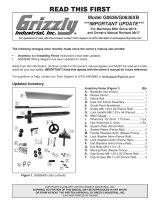
Introduction (Figure 1)


MODEL T21972
METAL
BLADE GUIDE SET
INSTRUCTIONS

WARNING: NO PORTION OF THIS MANUAL MAY BE REPRODUCED IN ANY SHAPE
OR FORM WITHOUT THE WRITTEN APPROVAL OF GRIZZLY INDUSTRIAL, INC.

Figure 1
Installing T21972 Upper Guides
1. 
2. 
3.       
      
      
Figure 2
4. 

5. 

6. 
      

Figure 2.


Figure 3.













7.      Figure 4
      
       



Figure 4.


Adjusting Support Bearings
1. 
2. 
Figure 5 

Figure 5. 
3.        
Figure 5 

 
     
Figure 6










Figure 6. 


4. 


       

      
     Figure 7 




Figure 7 






5. 
        

Figure 8


Figure 8. 




Figure 10. 




7. Figure 10

6. 
Figure 9 
       

Figure 9. 








8. 
  Figure 10    

9.       
 Figure 9     
       


   Figure 11   

Figure 11. 








10. 


       
         

Figure 7
      

11. Figure 9
      
        



12. 
Parts
3
1
2
4
5
6
7
8
8
9
10
11
12
13
14
15
15
16
17
18
19
7-1
7-1
REF PART # DESCRIPTION REF PART # DESCRIPTION
1 PLW03M LOCK WASHER 6MM 10 PR05M EXT RETAINING RING 15MM
2 PW03M FLAT WASHER 6MM 11 P6202ZZ BALL BEARING 6202ZZ
3 PB81M HEX BOLT M8-1.25 X 20 (LH) 12 PT21972012 UPPER BLADE GUIDE SUPPORT
4 PT21972004 LEFT COVER 13 PT21972013 UPPER GUIDE RING
5 PTS001M THUMB SCREW M6-1 X 16 14 PTS001M THUMB SCREW M6-1 X 16
6 PT21972006 LOWER BLADE GUIDE SUPPORT 15 PB18M HEX BOLT M6-1 X 15
7 PT21972007 LOWER GUIDE RING 16 PT21972016 ADJUST BAR
7-1 PSTB004M STEEL BALL 5MM 17 PT21972017 UPPER SPACING SLEEVE
8 PT21972008 LOWER ADJUST SHAFT 18 PT21972018 UPPER GUIDE SUPPORT BLOCK
9 PT21972009 RIGHT COVER 19 PSS11M SET SCREW M6-1 X 16
  • Page 1 1
  • Page 2 2
  • Page 3 3
  • Page 4 4

Grizzly T21972 Owner's manual

Type
Owner's manual

Grizzly T21972 is a set of blade guides designed to replace the original blade guides on G0513/G0514 series bandsaws. It consists of upper and lower blade guides, support bearings, and various screws and washers. The guides are adjustable, allowing you to align them precisely with the blade and achieve optimal blade tracking. The support bearings help to reduce friction and wear on the blade, extending its lifespan. With the Grizzly T21972, you can expect improved cutting accuracy, reduced blade vibration, and extended blade life.

Ask a question and I''ll find the answer in the document

Finding information in a document is now easier with AI