Page is loading ...

M
M
M
R
R
R
M
M
M
-
-
-
6
6
6
0
0
0
2
2
2
P
P
P
0
User Manual
“Modular” Seamless Multi-Format
Switch Scaler
with VGA, YPbPr, DVI and HDMI solutions
6x2
MRM-602P
V.2014MRM-602P.01

M
M
M
R
R
R
M
M
M
-
-
-
6
6
6
0
0
0
2
2
2
P
P
P
1
COPYRIGHT AND TRADEMARKS
All rights reserved by C&C TECHNIC TAIWAN CO., LTD. No part of this document may
be reproduced in any form or by any means without written permission from the product
manufacturer. Changes are periodically made to the information in this document.
They will be incorporated in subsequent editions. The product manufacturer may make
improvements and /or changes in the product described in this document at any time.
All the registered trademarks referred to this manual are belonging to their respective
companies.

M
M
M
R
R
R
M
M
M
-
-
-
6
6
6
0
0
0
2
2
2
P
P
P
2
BEFORE YOU BEGIN
Follow all instructions marked on the device during using.
Provide proper ventilation and air circulation and do not use near water.
It is better to keep it in a dry environment.
Place the device on a stable surface (example cart, stand, table, etc.).
The system should be installed indoor only. Install either on a sturdy rack or desk in a
well-ventilated place.
Make sure the rack is level and stable before extending a device from the rack.
Make sure all equipments installed on the rack including power strips and other
electrical connectors are properly grounded.
Only use the power cord supported with the device.
Do not use liquid or aerosol cleaners to clean the device.
Always unplug the power to the device before cleaning.
Unplug the power cord during lightning or after a prolonged period of non-use to avoid
damage to the equipment.
Do not stand on any device while installing the device to the rack.
Do not attempt to maintain the device by yourself, any faults, please contact your
vendor.
Save this manual properly for future reference.

M
M
M
R
R
R
M
M
M
-
-
-
6
6
6
0
0
0
2
2
2
P
P
P
3
TABLE OF CONTENTS
Copyright and Trademarks...................................................................................................... 1
Before You Begin ..................................................................................................................... 2
Table of Contents ..................................................................................................................... 3
Chapter 1 Switcher System Overview ................................................................................... 5
1.1 Introduction ................................................................................................................. 5
1.2 Packing ....................................................................................................................... 6
Chapter 2 Features .................................................................................................................. 7
Chapter 3 Specifications ......................................................................................................... 8
Chapter 4 Device Installation .................................................................................................. 9
Chapter 5 Front/Rear Panels .................................................................................................. 9
5.1 Front Panel ................................................................................................................. 9
5.2 IR Remote Controller ............................................................................................... 12
5.3 Rear Panel................................................................................................................ 13
Chapter 6 Connections.......................................................................................................... 16
6.1 Input/Output Connections ....................................................................................... 16
6.2 Switcher System Remote Control .......................................................................... 18
6.3 IR Connection .......................................................................................................... 19
6.4 Power Connection ................................................................................................... 19
6.5 Ports and Switchers ................................................................................................. 20
6.5.1 RS-232 ........................................................................................................... 20
6.5.2 RS-485 ........................................................................................................... 22
6.5.3 LAN Port ........................................................................................................ 23
6.5.4 DIP Switcher for 8 Pins ................................................................................ 23
6.5.5 Device ID Settings ........................................................................................ 24
6.5.6 DIP Switcher for 2 Pins ................................................................................ 25
Chapter 7 Switcher Application Software ............................................................................ 26
7.1 Software Introduction .............................................................................................. 26
7.1.1 Software Description .................................................................................... 26
7.1.2 Software Activation ....................................................................................... 26
7.1.3 Connect MRM-602P and PC ....................................................................... 27
7.2 Switcher Configuration ............................................................................................ 27
7.2.1 Main Operation Interface.............................................................................. 28
7.2.2 Disconnect Function Key ............................................................................. 30
7.2.3 Options Function ........................................................................................... 31
7.2.4 Communication Protocol/Control Command Code ................................... 31
7.3 LAN Web Configuration .......................................................................................... 32

M
M
M
R
R
R
M
M
M
-
-
-
6
6
6
0
0
0
2
2
2
P
P
P
4
7.3.1 Video Configuration ...................................................................................... 34
7.3.2 Device Status Information ............................................................................ 34
7.3.3 LAN IP Function ............................................................................................ 35
7.3.4 Other Application........................................................................................... 36
Chapter 8 Troubleshooting.................................................................................................... 37
Appendix A IR Controller ....................................................................................................... 39
Appendix B Firmware Upgrade ............................................................................................ 40
Appendix C RS-232 Communication Protocol .................................................................... 43
D-1 Host Request ........................................................................................................... 43
D-1.1 Device Byte .................................................................................................. 43
D-1.2 Request Byte ................................................................................................ 44
D-1.3 Index Byte ..................................................................................................... 46
D-1.4 Value Byte ..................................................................................................... 47
D-1.5 CRC Byte ...................................................................................................... 48
D-2 Device ACK Packet................................................................................................. 49
D-2.1 ACK Type A................................................................................................... 49
D-2.2 ACK Type B .................................................................................................. 50
D-2.3 ACK Type C .................................................................................................. 51
D-2.4 ACK Type D .................................................................................................. 52
D-2.5 ACK Type E .................................................................................................. 53

M
M
M
R
R
R
M
M
M
-
-
-
6
6
6
0
0
0
2
2
2
P
P
P
5
CHAPTER 1 SWITCHER SYSTEM OVERVIEW
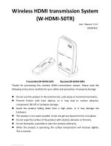
1.1 Introduction
The MRM-602P Switcher is a high performance, zero-second latency switching
equipment with 6x2 transmission interfaces. Through flexible and multiple video format
modular designs - VGA, YPbPr, DVI or HDMI modular card, each of them is independent
of all other cards in the system and quite easily swap through 2 screws only, the
multimedia signals come from these interfaces sources that you can transmit them
simultaneously to the VGA and HDMI output display, thereby minimizing signals
attenuation and ensuring high definition, integrating high fidelity graphics and multimedia
signal output. It features advanced video signal processing with up to 1080P
de-interlacing and true seamless switching for 1:1 or Full-screen processional-quality
aspect.
The MRM-602P Switcher is used mainly in TV broadcasting projects, multimedia
conference halls, and large display performances, TV teaching and command control
centers. It boasts features of power interruption protection during power surge, LCD
display and synchronous and integrate audio/visual switching functions. Beside it also
supports a RS-232 or LAN communication port enables convenient communication with
remote control equipment to switch the multimedia signals. Through a standard TCP/IP
connection with seamless integration in any existing network for easy remote access.
With easy operation, the MRM-602P Switcher allows you to use both pushbuttons and IR
remote control to operate the device.
Figure 1-1 MRM-602P Switcher

M
M
M
R
R
R
M
M
M
-
-
-
6
6
6
0
0
0
2
2
2
P
P
P
6
1.2 Packing
MRM-602P Switcher *1
RS-232 Communication Connected Cable *1
Power Cord *1
HDMI Cable *1
IR BOX*1
Female 1x5 Pole Captive Screw Socket * 1
Rack-Mount Bracket *2
Screws (for Brackets) *6
IR Remote Controller *1
Software CD *1 (Includes “AV Matrix Control Software”
and “User Manual”)

M
M
M
R
R
R
M
M
M
-
-
-
6
6
6
0
0
0
2
2
2
P
P
P
7
CHAPTER 2 FEATURES
Supports seamless switching with zero second latency upon different resolutions.
Flexible for having any combination of the preferred video (VGA, YPbPr, DVI or
HDMI) modular cards and very easy to swap via 2 screws only.
Up/down/cross converter equipped with VGA, YPbPr, DVI and HDMI inputs/
HDMI, VGA and Audio outputs.
- Supports interlaced video to progressive video. (like 1080i => 1080P)
- Supports up convert. (like VGA => 1080P@60)
- Supports down convert. (like 1080P@60 => 720P@60)
- Supports cross convert. (like 576i@50 => 1080P@60)
Resolution up to 1080P.
Supports 2 * aspect ratio modes.
- “1:1” Aspect ratio mode: This mode keeps the output image have the horizontal
and vertical ratio as same as the input image comes from the video. That makes
the output image has no distortion.
- “Full” Aspect ratio mode: This mode modifies the original input image comes
from the video to fit the aspect ratio of your output display. Sometimes the
image will be distorted so that it can fit in with the screen of your output display.
Centralized control upon series connections via RS-485
Supports both HDMI and VGA output.
Supports RS-232 serial control.
Supports RS-485 serial control
Supports Ethernet control.
Supports Audio input/output
Remote controller for up to 12 meters wireless operation.
Hot pluggable and 1U rack design.
EDID management (Copy from OUT port to 3*HDMI input).
HDCP Compliant

M
M
M
R
R
R
M
M
M
-
-
-
6
6
6
0
0
0
2
2
2
P
P
P
8
CHAPTER 3 SPECIFICATIONS
Hardware
Flexible Input Modular Card 1 x VGA, 1 x YPbPr, 1 x DVI, 3 x HDMI Females
Output Connector 1 x HDMI Type A Female, 1 x VGA HD15 Female
RS-232 Connector 1 x DB9 Female
RS-485 Connector 2
LAN Connector 1 x RJ-45
Audio Port 1 x Audio Out Port, 4 x Audio In Ports
2 pins Dip Switcher
1
8 pins Dip Switcher
1
Power 100VAC~240VAC, 50/60Hz, internal, switching
LED Indicators
10 x LED indicators specified for the connection is
“Selected”.
Housing Metal
Mounting Rack mountable (1U-rack-mount kit)
Weight 3077g
Dimensions (LxWxH) 440x240x43 mm
Multimedia
Max. Resolution 1080P
Max Pixel Clocks 225MHz
Control Information
HDMI Cable Distance
At least 10 meters
Ethernet Protocol
HTTP, DHCP, TCP/IP, ICMP (ping)
Program Control
Web Server, AVM Application
Serial Control Port
RS-232: 9 Pin Female D Type Connector
RS-485: 1x5 Pole Captive Screw
Remote Control
Remote Controller, IR Receiver
Web Server
LAN (RJ-45)

M
M
M
R
R
R
M
M
M
-
-
-
6
6
6
0
0
0
2
2
2
P
P
P
9
CHAPTER 4 DEVICE INSTALLATION
The Switcher has a black metallic housing. It can be placed on a sturdy desk directly or
installed on a bracket. See Figure 4-1 below:
Figure 4-1 Mount the Device on a Standard Bracket with 1U Rack-mount
CHAPTER 5 FRONT/REAR PANELS
5.1 Front Panel
Figure 5-1 MRM-602P Switcher Front Panel
The MRM-602P Switcher supports up to 6 switching keys on the Front Panel for
indicating the connection status that allows you to switch connected sources quickly.
Key1~6: Specifies the one of input channels that comes from VGA, YPbPr, DVI or
HDMI1~4 interface to the HDMI or VGA output. These keys configure the signal
sources of channel1~6. You can also use these keys to switch input channels.
Only one of input channels can be configured as output source.

M
M
M
R
R
R
M
M
M
-
-
-
6
6
6
0
0
0
2
2
2
P
P
P
10
Aspect: The MRM-602P Switcher allows you to configure the Aspect ratio of the output
image including Full and 1:1 Aspect.
Figure 5-2 Full Aspect
When the Full aspect for the output image is configured, the FULL LED indicator on
the front panel will become solid green.
Figure 5-3 1:1 Aspect
When the 1:1 aspect for the output image is configured, the 1:1 LED indicator will
become solid green.
Resolution: The MRM-602P Switcher supports you 720P and 1080P output
resolutions. It can transform the input source to available output resolution.
MRM-602P supports you the seamless switching between video signals on different
channels are provided. .

M
M
M
R
R
R
M
M
M
-
-
-
6
6
6
0
0
0
2
2
2
P
P
P
11
IR: Infrared receiver for the MRM-602P Switcher. The longest distance of your IR
remote controller to receive the signals is about 12 meters.
Figure 5-4 IR Receiving Distance

M
M
M
R
R
R
M
M
M
-
-
-
6
6
6
0
0
0
2
2
2
P
P
P
12
5.2 IR Remote Controller
Figure 5-5 IR Remote Controller
Main Channel Port selection:
Press the Number#1~6 button to select the key channel on the front panel.
Example: Press the “5” button on the Remote controller specified the input signal of the
key on the front panel comes from the channel#5 (HDMI INPUT 5 interface on the rear
panel).

M
M
M
R
R
R
M
M
M
-
-
-
6
6
6
0
0
0
2
2
2
P
P
P
13
5.3 Rear Panel
Figure 5-6 MRM-602P Switcher Rear Panel
The MRM-602P Switcher supports up to 6 input and 2 output jacks on the rear panel,
each female terminal separately form the signal input and output jacks. The flexible
modules cards specified as “INPUT1” (VGA+AUDIO), “INPUT2” (YPbPr+AUDIO),
“INPUT3” (DVI+AUDIO) and “INPUT4~6” (HDMI interfaces) are for signals input. The
input terminals supply you to connect to different equipments including CD/DVD players,
Blue Ray player, PS3, Video Camera, STB and so on. The output terminal with “HDMI
OUT” and “VGA OUT” interfaces can be connected to projectors, video recorders,
multiplexers and other displayers.
Power port: The Power Port is applicable for 100~240VAC, 50~60Hz connected to the
outlet of power source. Refer to 6.4 Power Connection
.
Power Switch: To switch power ON or OFF the Switcher.
IR port: This is used for connecting the IR Receiver. Refer to 6.3 IR Connection.
Figure 5-7 IR Receiver Pin Definition
LAN Port: Use the RJ-45 connection cable to connect the Internet and the MRM-602P
Switcher. The entire PC at the same network can control the MRM-602P Switcher
through the LAN port. Refer to 6.5.3 LAN Port.
RS-232 connector: Use a 9-pin RS-232 cable to connect both computer serial port
(COM1 or COM2) and the MRM-602P’s RS-232 communication connector, refer to
6.5.1 RS-232. The computer can then be deployed to control the MRM-602P after
installing of application software. Refer to 7.1 Software Introduction for a software
control or Appendix C RS-232 Communication Protocol for an individual configuration.
RS-485: Connection ports allow you to connect/control more than one Switcher
product.

M
M
M
R
R
R
M
M
M
-
-
-
6
6
6
0
0
0
2
2
2
P
P
P
14
DIP Switcher: 8 pins DIP and 2 pins DIP switchers for connected configurations. For
more information, refer to 6.5 Ports and Switchers.
8 pins DIP switchers:
- Pin 1~Pin5: ID
- Pin 6: Master/Slave
- Pin 7: RS-232/LAN
- Pin 8: IP RESET
-
2 pins DIP switchers (DIP Switch RS-485 Terminator): RS-485 Terminator for
ON/OFF
VGA OUT connector: The VGA OUT connector is connected to the Monitor, HDTVs or
other output devices through a VGA cable.
AUDIO OUT port: This port is connected to the speaker or other audio output devices
HDMI OUT connector: The MRM-602P Switcher Output connector is connected to the
A/V, HDTVs or other output devices.
INPUT 1~6 modular cards: The MRM-602P Switcher Input modular cards are
connected to the DVDs, CD players, PS3 or other input sources.
- INPUT1 (VGA + AUDIO)
- INPUT2 (YPbPr + AUDIO)
- INPUT3 (DVI + AUDIO)
- INPUT4~6 (HDMI)
VGA E-DDC host assignment:
Pin #
Signal
Pin #
Signal
1 Red
9 DDC 5V supply
2 Green
10 Sync return
3 Blue
11 Monitor ID bit 0
4 Monitor ID bit
12
Bi-directional data
(SDA)
5 Return (GND)
13 Horizontal sync
6 Red return
14 Vertical sync
7 Green return
15 Data clock (SCL)
8 Blue return

M
M
M
R
R
R
M
M
M
-
-
-
6
6
6
0
0
0
2
2
2
P
P
P
15
DVI connector host assignment:
Pin #
Signal
Pin #
Signal
1 TMSD data 2-
13 TMDS data 3+
2 TMDS data 2+
14 +5V
3 TMDS data 2/4 shield
15 Ground
4 TMDS data 4-
16 Hot plug detect
5 TMDS data 4+
17 TMDS data 0-
6 DDC clock
18 TMDS data 0+
7 DDC data
19 TMDS data 0/5 shield
8 Analog vertical sync
20 TMDS data 5-
9 TMDS data 1-
21 TMDS data 5+
10 TMDS data 1+
22 TMDS clock shield
11 TMDS data 1/3 shield
23 TMDS clock+
12 TMDS data 3-
24 TMDS clock-
HDMI Type A Connector host assignment:
Pin #
Signal
Pin #
Signal
1 TMDS Data2+
11 TMDS Clock Shield
2 TMDS Data2 Shield
12 TMDS Clock-
3 TMDS Data2-
13 NC
4 TMDS Data1+
14 NC
5 TMDS Data1 Shield
15 DDC-SCL
6 TMDS Data1-
16 DDC-SDA
7 TMDS Data0+
17 DDC-Ground
8 TMDS Data0 Shield
18 +5V Power
9 TMDS Data0- 19 Hot Plug Detect
10 TMDS Clock+
AUDIO IN ports: These ports are complied with VGA, YPbPr and DVI connecters that
are connected to the audio signal sources.
INPUT1~3 are customize modular cards with flexible combination of VGA+AUDIO,
YPbPr+AUDIO and DVI+AUDIO interfaces.

M
M
M
R
R
R
M
M
M
-
-
-
6
6
6
0
0
0
2
2
2
P
P
P
16
CHAPTER 6 CONNECTIONS
Figure 6-1 MRM-602P Connections
6.1 Input/Output Connections
Use the VGA/YPbPr/DVI/HDMI connecting cable to connect the Input modular card
(INPUT1 ~ INPUT 6) on the rear panel to the output connector of the sources (CD/DVD
player/Camera/ PS3/STB/PC). And use the HDMI or VGA connecting cable to connect
the output connector (HDMI OUT/VGA OUT) on the rear panel to the input connector of
the HDMI TV, displays, multiplexers and so on.
Figure 6-2 Input Connections

M
M
M
R
R
R
M
M
M
-
-
-
6
6
6
0
0
0
2
2
2
P
P
P
17
Figure 6-3 Output Connection

M
M
M
R
R
R
M
M
M
-
-
-
6
6
6
0
0
0
2
2
2
P
P
P
18
6.2 Switcher System Remote Control
Use the RS-232 connecting cable to connect the computer serial communication port
(COM1 or COM2) to the RS-232 communication port of the MRM-602P Switcher. The
computer can then be used to control the MRM-602P Switcher after installing of
application software. Aside from using the front panel keys for switching operation, you
are also permitted to use the RS-232 connection port for a remote operation.
Figure 6-4 RS-232 and Control PC connection
The MRM-602P Switcher also supports a LAN port allows you to control all the series
connection devices through PC Browser.
Figure 6-5 LAN port and Control PC Connection
The MRM-602P Switcher supports RS-232 and LAN port on the rear panel for a
remote control and allows you to operate settings via the keys located on the front
panel.

M
M
M
R
R
R
M
M
M
-
-
-
6
6
6
0
0
0
2
2
2
P
P
P
19
6.3 IR Connection
The MRM-602P Switcher provides you an IR receiver for more convenient to react to the
controller. If it is difficult for you to aim at IR receiver on the front panel due to the location
of Switcher, please connect it to the IR port located on the rear panel for optional
position.
Figure 6-6 IR Extended Aiming
6.4 Power Connection
Use the included power cord to connect from the power port on the rear panel of the
MRM-602P Switcher to the outlet.
Figure 6-7 Power Connection
/