Page is loading ...

1604-VLZ PRO
16-CHANNEL
MIC
/
LINE MIXER
OWNER’S MANUAL
16151413121110987654321
PAN
AUX
3
1
2
1
2
1
2
1
2
1
2
1
2
1
2
1
2
1
2
1
2
1
2
1
2
1
2
1
2
1
2
1
2
EQ
5
4
6
5/6
SHIFT
PRE
PRE PRE
PRE PRE PRE PRE PRE PRE PRE PRE PRE PRE PRE
PRE
PRE
TRIM
12
3
4 5 6 7 8 9 10 11 12 13
14
15 16
SOLO
L - R
3
–
4
1
–
2
SOLO
L - R
3
–
4
1
–
2
SOLO
L - R
3
–
4
1
–
2
SOLO
L - R
3
–
4
1
–
2
SOLO
L - R
3
–
4
1
–
2
SOLO
L - R
3
–
4
1
–
2
SOLO
L - R
3
–
4
1
–
2
SOLO
L - R
3
–
4
1
–
2
SOLO
L - R
3
–
4
1
–
2
SOLO
L - R
3
–
4
1
–
2
SOLO
L - R
3
–
4
1
–
2
SOLO
L - R
3
–
4
1
–
2
SOLO
L - R
3
–
4
1
–
2
SOLO
L - R
3
–
4
1
–
2
SOLO
L - R
3
–
4
1
–
2
SOLO
L - R
3
–
4
1
–
2
OL
-
20
OL
-
20
OL
-
20
OL
-
20
OL
-
20
OL
-
20
OL
-
20
OL
-
20
OL
-
20
OL
-
20
OL
-
20
OL
-
20
OL
-
20
OL
-
20
OL
-
20
OL
-
20
PAN
AUX
3
EQ
5
4
6
5/6
SHIFT
PAN
AUX
3
EQ
5
4
6
5/6
SHIFT
PAN
AUX
3
EQ
5
4
6
5/6
SHIFT
PAN
AUX
3
EQ
5
4
6
5/6
SHIFT
PAN
AUX
3
EQ
5
4
6
5/6
SHIFT
PAN
AUX
3
EQ
5
4
6
5/6
SHIFT
PAN
AUX
3
EQ
5
4
6
5/6
SHIFT
PAN
AUX
3
EQ
5
4
6
5/6
SHIFT
PAN
AUX
3
EQ
5
4
6
5/6
SHIFT
PAN
AUX
3
EQ
5
4
6
5/6
SHIFT
PAN
AUX
3
EQ EQ
5
4
6
5/6
SHIFT
PAN
AUX
3
5
4
6
5/6
SHIFT
PAN
AUX
3
EQ
5
4
6
5/6
SHIFT
PAN
AUX
3
EQ
5
4
6
5/6
SHIFT
PAN
AUX
3
EQ
5
4
6
5/6
SHIFT
TRIM TRIM TRIM TRIM TRIM TRIM TRIM TRIM TRIM TRIM TRIM TRIM TRIM TRIM TRIM
TRACK
8
TRACK
7
TRACK
6
TRACK
5
TRACK
4
TRACK
3
TRACK
2
TRACK
1
U
OO
+15
U
OO
+15
U
OO
+15
U
+15-15
U
+15-15
800
2k200
8k
U
+15-15
12k
HI
MID
80Hz
LOW CUT
75 Hz
18dB/OCT
LOW
100
+15-15
800
2k200
8k100
+15-15
800
2k200
8k100
+15-15
800
2k200
8k100
+15-15
800
2k200
8k100
+15-15
800
2k200
8k100
+15-15
800
2k200
8k100
+15-15
800
2k200
8k100
+15-15
800
2k200
8k100
+15-15
800
2k200
8k
100
+15-15
800
2k200
8k100
+15-15
800
2k200
8k
100
+15-15
800
2k200
8k
100
+15-15
800
2k200
8k
100
+15-15
800
2k200
8k
100
+15-15
800
2k200
8k100
U
OO
+15
U
OO
+15
U
OO
+15
U
OO
+15
U
OO
+15
U
OO
+15
U
OO
+15
U
OO
+15
U
OO
+15
U
OO
+15
U
OO
+15
U
OO
+15
U
OO
+15
U
OO
+15
U
OO
+15
U
OO
+15
U
OO
+15
U
OO
+15
U
OO
+15
U
OO
+15
U
OO
+15
U
OO
+15
U
OO
+15
U
OO
+15
U
OO
+15
U
OO
+15
U
OO
+15
U
OO
+15
U
OO
+15
U
OO
+15
U
OO
+15
1
MUTE
U
OO
+15
U
+15-15
U
U
+15-15
12k
HI
MID
80Hz
LOW CUT
75 Hz
18dB/OCT
LOW
U
OO
+15
2
MUTE
U
OO
+15
U
+15-15
U
U
+15-15
12k
HI
MID
80Hz
LOW CUT
75 Hz
18dB/OCT
LOW
U
OO
+15
3
MUTE
U
OO
+15
U
+15-15
U
U
+15-15
12k
HI
MID
80Hz
LOW CUT
75 Hz
18dB/OCT
LOW
U
OO
+15
4
MUTE
U
OO
+15
U
+15-15
U
U
+15-15
12k
HI
MID
80Hz
LOW CUT
75 Hz
18dB/OCT
LOW
U
OO
+15
5
MUTE
U
OO
+15
U
+15-15
U
U
+15-15
12k
HI
MID
80Hz
LOW CUT
75 Hz
18dB/OCT
LOW
U
OO
+15
6
MUTE
U
OO
+15
U
+15-15
U
U
+15-15
12k
HI
MID
80Hz
LOW CUT
75 Hz
18dB/OCT
LOW
U
OO
+15
7
MUTE
U
OO
+15
U
+15-15
U
U
+15-15
12k
HI
MID
80Hz
LOW CUT
75 Hz
18dB/OCT
LOW
U
OO
+15
8
MUTE
U
OO
+15
U
+15-15
U
U
+15-15
12k
HI
MID
80Hz
LOW CUT
75 Hz
18dB/OCT
LOW
U
OO
+15
9
MUTE
U
OO
+15
U
+15-15
U
U
+15-15
12k
HI
MID
80Hz
LOW CUT
75 Hz
18dB/OCT
LOW
U
OO
+15
10
MUTE
U
OO
+15
U
+15-15
U
U
+15-15
12k
HI
MID
80Hz
LOW CUT
75 Hz
18dB/OCT
LOW
U
OO
+15
11
MUTE
U
OO
+15
U
+15-15
U
U
+15-15
12k
HI
MID
80Hz
LOW CUT
75 Hz
18dB/OCT
LOW
U
OO
+15
12
MUTE
U
OO
+15
U
+15-15
U
U
+15-15
12k
HI
MID MID MID MID
80Hz
LOW CUT
75 Hz
18dB/OCT
LOW
U
OO
+15
13
MUTE
U
OO
+15
U
+15-15
U
U
+15-15
12k
HI
80Hz
LOW CUT
75 Hz
18dB/OCT
LOW
U
OO
+15
14
MUTE
U
OO
+15
U
+15-15
U
U
+15-15
12k
HI
80Hz
LOW CUT
75 Hz
18dB/OCT
LOW
U
OO
+15
15
MUTE
U
OO
+15
U
+15-15
U
U
+15-15
12k
HI
80Hz
LOW CUT
75 Hz
18dB/OCT
LOW
U
OO
+15
16
MUTE
M
I
C
G
A
I
N
060
+15dB -45dB
-
1
0
d
B
V
M
I
C
G
A
I
N
060
+15dB -45dB
-
1
0
d
B
V
M
I
C
G
A
I
N
060
+15dB -45dB
-
1
0
d
B
V
M
I
C
G
A
I
N
060
+15dB -45dB
-
1
0
d
B
V
M
I
C
G
A
I
N
060
+15dB -45dB
-
1
0
d
B
V
M
I
C
G
A
I
N
060
+15dB -45dB
-
1
0
d
B
V
M
I
C
G
A
I
N
060
+15dB -45dB
-
1
0
d
B
V
M
I
C
G
A
I
N
060
+15dB -45dB
-
1
0
d
B
V
M
I
C
G
A
I
N
060
+15dB -45dB
-
1
0
d
B
V
M
I
C
G
A
I
N
060
+15dB -45dB
-
1
0
d
B
V
M
I
C
G
A
I
N
060
+15dB -45dB
-
1
0
d
B
V
M
I
C
G
A
I
N
060
+15dB -45dB
-
1
0
d
B
V
M
I
C
G
A
I
N
060
+15dB -45dB
-
1
0
d
B
V
M
I
C
G
A
I
N
060
+15dB -45dB
-
1
0
d
B
V
M
I
C
G
A
I
N
060
+15dB -45dB
-
1
0
d
B
V
M
I
C
G
A
I
N
060
+15dB -45dB
-
1
0
d
B
V
UUUU
UUUUUUUUUUUU
LR LR LR LR LR LR LR LR LR LR LR LR LR LR LR LR
OOOOOOOOOOOOOOOOOOOOOOOOOOOOOOOO
AUX
SEND
STEREO AUX RETURN
EFFECTS TO
MONITORS
TO AUX
SEND 2
TO AUX
SEND 1
1
2
PWR
PHAN
SOLO
SOLO
1
2
1
2
3
4
1
2
C
-
R / PHNS
ONLY
RETURNS
SOLO
MAIN MIX
TO SUBS
ASSIGN OPTIONS
1
–
2
3
–
4
U
OO
+20
U
OO
+20
U
OO
+15
U
OO
+15
U
OO
+20
U
OO
+20
U
OO
+10
U
OO
+10
LEFT RIGHT
PHONES
LAMP
12V
0.5A
TAPE IN
SOLO
RUDE
SOLO
LIGHT
CTL ROOM / PHONES
SUBS 3
–
4
SUBS 1
–
2
MAIN MIX
CTL ROOM
SOURCE
TAPE
TAPE TO
MAIN MIX
MAIN
MIX
RIGHT
1234
LEFT
RIGHT
LEFT
RIGHT
LEFT
RIGHT
LEFT
28
10
7
4
2
2
0
4
7
10
20
30
ASSIGN TO MAIN MIX
LEVEL
SET
MODE
(AFL)
LEVEL SET
NORMAL
(PFL)
U
OO
+20
OO
OO
MAX
0 dB=0 dBu
MAX
dB
30
20
10
OO
40
50
5
5
U
60
10
dB
30
20
10
OO
40
50
5
5
U
60
10
1604-VLZPRO
16- CHANNEL MIC /L INE MIXER
WITH PREMIUM XDR
TM
MIC PREAMPLIFIERS
1604-VLZPRO
16- CHANNEL MIC /LINE MI XER
WITH PREMIUM XDR
TM
MIC PREAMPLIFIERS
UTILISE UN FUSIBLE DE RECHANGE DE MÊME TYPE. DEBRANCHER AVANT DE REMPLACER LE FUSIBLE
4321
INSERT INSERT INSERT
LINE
INSERT
MIC 4 MIC 3 MIC 2
MIC 1
BAL
UN-
BAL
BAL
UN-
BAL
BAL
UN-
BAL
BAL
UN-
BAL
LINELINELINE
OO
+6
PHANTOM
ON
POWER
ON
120 VAC 50/60 Hz 20W
1A/250V SLO-BLO
16
15 14 13 12 11 10 9 8 7 6 5
MIC 16
INSERT
INSERT INSERT INSERT INSERT INSERT INSERT INSERT INSERT INSERT INSERT INSERT
MIC 15 MIC 14 MIC 13 MIC 12 MIC 11 MIC 10 MIC 9 MIC 8 MIC 7 MIC 6 MIC 5
SUB OUTC-R OUT
MAIN INSERT
(TIP SEND
RING RETURN)
TAPE TAPE
MAIN OUT
AUX SEND
DIRECT OUT
AUX RETURN
3
R
L
MONO
R
R
R
R
L
R
L
R
L
R
L
LLL
1
42
5
1234
31
642
753
864
1
2
BAL/UNBAL
BAL/UNBAL BAL/UNBAL
BAL/UNBAL
BAL/UNBAL BAL/UNBAL
INPUT OUTPUT
R
L
(MONO)(MONO)(MONO)
BAL
UN-
BAL
BAL
UN-
BAL
BAL
UN-
BAL
BAL
UN-
BAL
BAL
UN-
BAL
BAL
UN-
BAL
BAL
UN-
BAL
BAL
UN-
BAL
BAL
UN-
BAL
BAL
UN-
BAL
BAL
UN-
BAL
BAL
UN-
BAL
LINELINELINELINELINELINE
LINELINELINELINELINELINE
TO REDUCE THE RISK OF
FIRE REPLACE WITH SAME
TYPE FUSE AND RATING
CAUTION:
UTILISE UN FUSIBLE DE RECHANGE DE MÊME TYPE. DEBRANCHER AVANT DE REMPLACER LE FUSIBLE
CONCEIVED, DESIGNED, AND MANUFACTURED BY MACKIE DESIGNS INC • WOODINVILLE • WA • USA • MADE IN USA • FABRIQUE AU USA • COPYRIGHT ©1998 • THE FOLLOWING ARE TRADEMARKS OR REGISTERED TRADEMARKS OF MACKIE DESIGN INC.: "MACKIE", "VLZ", "XDR", AND THE "RUNNING MAN" FIGURE • US PATENT NUMBER 29/049,129
XDR
TM
EXTENDED DYNAMIC RANGE MIC PREAMPLIFIERS ARE PROPRIETARY TO MACKIE DESIGNS, INC.
X
D
R
M
I
C
P
R
E
X
D
R
M
I
C
P
R
E
X
D
R
M
I
C
P
R
E
X
D
R
M
I
C
P
R
E
X
D
R
M
I
C
P
R
E
X
D
R
M
I
C
P
R
E
X
D
R
M
I
C
P
R
E
X
D
R
M
I
C
P
R
E
X
D
R
M
I
C
P
R
E
X
D
R
M
I
C
P
R
E
X
D
R
M
I
C
P
R
E
X
D
R
M
I
C
P
R
E
X
D
R
M
I
C
P
R
E
X
D
R
M
I
C
P
R
E
X
D
R
M
I
C
P
R
E
X
D
R
M
I
C
P
R
E

CAUTION AVIS
RISK OF ELECTRIC
SHOCK
DO NOT OPEN
RISQUE DE
CHOC
ELECTRIQUE
NE PAS OUVRIR
CAUTION: TO REDUCE THE RISK OF ELECTRIC SHOCK
DO NOT REMOVE COVER (OR BACK)
NO USER-SERVICEABLE PARTS INSIDE
REFER SERVICING TO QUALIFIED PERSONNEL
ATTENTION: POUR EVITER LES RISQUES DE CHOC
ELECTRIQUE, NE PAS ENLEVER LE COUVERCLE. AUCUN
ENTRETIEN DE PIECES INTERIEURES PAR L'USAGER. CONFIER
L'ENTRETIEN AU PERSONNEL QUALIFIE.
AVIS: POUR EVITER LES RISQUES D'INCENDIE OU
D'ELECTROCUTION, N'EXPOSEZ PAS CET ARTICLE
A LA PLUIE OU A L'HUMIDITE
The lightning flash with arrowhead symbol within an equilateral
triangle is intended to alert the user to the presence of uninsulated
"dangerous voltage" within the product's enclosure, that may be
of sufficient magnitude to constitute a risk of electric shock to persons.
Le symbole éclair avec point de flèche à l'intérieur d'un triangle
équilatéral est utilisé pour alerter l'utilisateur de la présence à
l'intérieur du coffret de "voltage dangereux" non isolé d'ampleur
suffisante pour constituer un risque d'éléctrocution.
The exclamation point within an equilateral triangle is intended to
alert the user of the presence of important operating and maintenance
(servicing) instructions in the literature accompanying the appliance.
Le point d'exclamation à l'intérieur d'un triangle équilatéral est
employé pour alerter les utilisateurs de la présence d'instructions
importantes pour le fonctionnement et l'entretien (service) dans le
livret d'instruction accompagnant l'appareil.
SAFETY INSTRUCTIONS
1. Read Instructions — All the safety and operation
instructions should be read before this Mackie product is
operated.
2. Retain Instructions — The safety and operating instruc-
tions should be kept for future reference.
3. Heed Warnings — All warnings on this Mackie product and
in these operating instructions should be followed.
4. Follow Instructions — All operating and other instructions
should be followed.
5. Water and Moisture — This Mackie product should not be
used near water – for example, near a bathtub, washbowl,
kitchen sink, laundry tub, in a wet basement, near a
swimming pool, swamp or salivating St. Bernard dog, etc.
6. Heat — This Mackie product should be situated away
from heat sources such as radiators, or other devices which
produce heat.
7. Power Sources — This Mackie product should be
connected to a power supply only of the type described in
these operation instructions or as marked on this Mackie
product.
8. Power Cord Protection — Power supply cords should be
routed so that they are not likely to be walked upon or
pinched by items placed upon or against them, paying
particular attention to cords at plugs, convenience receptacles,
and the point where they exit this Mackie product.
9. Object and Liquid Entry — Care should be taken so that
objects do not fall into and liquids are not spilled into the
inside of this Mackie product.
10. Damage Requiring Service — This Mackie product should
be serviced only by qualified service personnel when:
A. The power-supply cord or the plug has been
damaged; or
B. Objects have fallen, or liquid has spilled into
this Mackie product; or
C. This Mackie product has been exposed to rain;
or
D. This Mackie product does not appear to operate
normally or exhibits a marked change in
performance; or
E. This Mackie product has been dropped, or its
chassis damaged.
11. Servicing — The user should not attempt to service this
Mackie product beyond those means described in this
operating manual. All other servicing should be referred to the
Mackie Service Department.
12. To prevent electric shock, do not use this polarized plug
with an extension cord, receptacle or other outlet unless the
blades can be fully inserted to prevent blade exposure.
Pour préevenir les chocs électriques ne pas utiliser cette fiche
polariseé avec un prolongateur, un prise de courant ou une
autre sortie de courant, sauf si les lames peuvent être insérées
à fond sans laisser aucune pariie à découvert.
13 . Grounding or Polarization — Precautions should be taken
so that the grounding or polarization means of this Mackie
product is not defeated.
14 . This apparatus does not exceed the Class A/Class B
(whichever is applicable) limits for radio noise emissions from
digital apparatus as set out in the radio interference
regulations of the Canadian Department of Communications.
ATTENTION —Le présent appareil numérique n’émet pas de
bruits radioélectriques dépassant las limites applicables aux
appareils numériques de class A/de class B (selon le cas)
prescrites dans le règlement sur le brouillage radioélectrique
édicté par les ministere des communications du Canada.
15 . To prevent hazard or damage, ensure that only
microphone cables and microphones designed to IEC 268-15A
are connected.
WARNING — To reduce the risk of fire or electric shock, do
not expose this appliance to rain or moisture.

3
We realize that you must have a powerful
hankerin’ to try out your new 1604-VLZ
PRO. Or
you might be one of those people who never
reads manuals. Either way, all we ask is that
you read this page NOW, and the rest can wait
until you’re good and ready. But do read it —
you’ll be glad you did.
Other Nuggets of Wisdom
For optimum sonic performance, the channel
faders and the
MAIN MIX
fader should be set near
the “
U
” (unity gain) markings.
Always turn the
MAIN MIX
fader and
CTL
ROOM/PHONES
knob down before making con-
nections to and from your 1604-VLZ
PRO.
If you shut down your equipment, turn off your
amplifiers first. When powering up, turn on your
amplifiers last.
Save the shipping box! You may need it
someday, and you don’t want to have to pay for
another one.
INSTANT MIXING
Here’s how to get going
right away, assuming you own a
microphone and a keyboard:
1.Plug your microphone into Channel 1’s
MIC
input.
2.Turn on the 1604-VLZ
PRO.
3.Perform the Level-Setting Procedure .
4.Connect cords from the
MAIN OUT
jacks to
your amplifier.
5.Hook up speakers to the amp and turn it on.
6.Set channel 1’s fader to the “U” mark.
7.Engage (push in) Channel 1’s
L-R
switch.
8.Set the
MAIN MIX
fader one-quarter of the
way up.
9.Sing like a canary!
10.Plug your keyboard into channels 3 and 4.
11.Turn channel 3’s
PAN
knob fully left and
channel 4’s
PAN
knob fully right.
12.Set those faders to the “U” mark.
13.
Perform the Level-Setting Procedure .
14.
Engage the
L-R
switch on these channels.
15.Play like a madman and sing like a canary!
It’s your first mix!
READ THIS PAGE!!!
Please write your serial number here for
future reference (i.e. insurance claims, tech
support, return authorization, etc.):
Part No. 820-034-01 Rev. A1 04/99
©1999 Mackie Designs, All Rights Reserved.
Printed in the U.S.A.
LEVEL-SETTING PROCEDURE
Message to seasoned pros: do NOT set levels
using the old “Turn the trim up until the clip
light comes on, then back off a hair” trick. When a
Mackie Designs mixer clip light comes on, you
really are about to clip.
This procedure really works — it assures
low noise and high headroom. Please read on.
It’s not even necessary to hear what you’re do-
ing to set optimal levels. But if you’d like to: Plug
headphones into the
PHONES
output jack,
then set the
C-R PHONES
knob about one-
quarter of the way up.
The following steps must be performed one
channel at a time:
1.Turn the
TRIM
,
AUX
send and fader
controls fully down.
2.Be sure the
1–2
,
3–4
and
L–R
channel
assignment switches are all disengaged.
3.Set the
EQ
knobs at the center detents.
4.Connect the signal source to the
MIC
or
LINE
channel input.
5.Engage (push in) the channel’s
SOLO
switch.
6.Push in the
MODE
switch in the output
section (
LEVEL SET (PFL)
mode) — the
LEVEL SET
LED will light.
7.Play something into the selected input, at
real-world levels.
8.Adjust the
TRIM
control so that the
display on the meter stays around “0.”
(Only the left meter is active in the
Level-Setting Procedure.)
9.If you’d like to apply some
EQ
, do so
now and return to the previous step.
10.Disengage that channel’s
SOLO
switch.
11.Repeat for each of channels 1–16.
Purchased at:
Date of purchase:

4
PAN
AUX
3
1
2
1
2
1
2
1
2
1
2
1
2
1
2
1
2
1
2
1
2
1
2
1
2
1
2
1
2
1
2
1
2
EQ
5
4
6
5/6
SHIFT
PRE
PRE PRE
PRE PRE PRE PRE PRE PRE PRE PRE PRE PRE PRE
PRE
PRE
TRIM
12
3
4 5 6 7 8 9 10 11 12 13
14
15 16
SOLO
L - R
3
–
4
1
–
2
SOLO
L - R
3
–
4
1
–
2
SOLO
L - R
3
–
4
1
–
2
SOLO
L - R
3
–
4
1
–
2
SOLO
L - R
3
–
4
1
–
2
SOLO
L - R
3
–
4
1
–
2
SOLO
L - R
3
–
4
1
–
2
SOLO
L - R
3
–
4
1
–
2
SOLO
L - R
3
–
4
1
–
2
SOLO
L - R
3
–
4
1
–
2
SOLO
L - R
3
–
4
1
–
2
SOLO
L - R
3
–
4
1
–
2
SOLO
L - R
3
–
4
1
–
2
SOLO
L - R
3
–
4
1
–
2
SOLO
L - R
3
–
4
1
–
2
SOLO
L - R
3
–
4
1
–
2
OL
-
20
OL
-
20
OL
-
20
OL
-
20
OL
-
20
OL
-
20
OL
-
20
OL
-
20
OL
-
20
OL
-
20
OL
-
20
OL
-
20
OL
-
20
OL
-
20
OL
-
20
OL
-
20
PAN
AUX
3
EQ
5
4
6
5/6
SHIFT
PAN
AUX
3
EQ
5
4
6
5/6
SHIFT
PAN
AUX
3
EQ
5
4
6
5/6
SHIFT
PAN
AUX
3
EQ
5
4
6
5/6
SHIFT
PAN
AUX
3
EQ
5
4
6
5/6
SHIFT
PAN
AUX
3
EQ
5
4
6
5/6
SHIFT
PAN
AUX
3
EQ
5
4
6
5/6
SHIFT
PAN
AUX
3
EQ
5
4
6
5/6
SHIFT
PAN
AUX
3
EQ
5
4
6
5/6
SHIFT
PAN
AUX
3
EQ
5
4
6
5/6
SHIFT
PAN
AUX
3
EQ EQ
5
4
6
5/6
SHIFT
PAN
AUX
3
5
4
6
5/6
SHIFT
PAN
AUX
3
EQ
5
4
6
5/6
SHIFT
PAN
AUX
3
EQ
5
4
6
5/6
SHIFT
PAN
AUX
3
EQ
5
4
6
5/6
SHIFT
TRIM TRIM TRIM TRIM TRIM TRIM TRIM TRIM TRIM TRIM TRIM TRIM TRIM TRIM TRIM
TRACK
8
TRACK
7
TRACK
6
TRACK
5
TRACK
4
TRACK
3
TRACK
2
TRACK
1
U
OO
+15
U
OO
+15
U
OO
+15
U
+15-15
U
+15-15
800
2k200
8k
U
+15-15
12k
HI
MID
80Hz
LOW CUT
75 Hz
18dB/OCT
LOW
100
+15-15
800
2k200
8k100
+15-15
800
2k200
8k100
+15-15
800
2k200
8k100
+15-15
800
2k200
8k100
+15-15
800
2k200
8k100
+15-15
800
2k200
8k100
+15-15
800
2k200
8k100
+15-15
800
2k200
8k100
+15-15
800
2k200
8k
100
+15-15
800
2k200
8k100
+15-15
800
2k200
8k
100
+15-15
800
2k200
8k
100
+15-15
800
2k200
8k
100
+15-15
800
2k200
8k
100
+15-15
800
2k200
8k100
U
OO
+15
U
OO
+15
U
OO
+15
U
OO
+15
U
OO
+15
U
OO
+15
U
OO
+15
U
OO
+15
U
OO
+15
U
OO
+15
U
OO
+15
U
OO
+15
U
OO
+15
U
OO
+15
U
OO
+15
U
OO
+15
U
OO
+15
U
OO
+15
U
OO
+15
U
OO
+15
U
OO
+15
U
OO
+15
U
OO
+15
U
OO
+15
U
OO
+15
U
OO
+15
U
OO
+15
U
OO
+15
U
OO
+15
U
OO
+15
U
OO
+15
1
MUTE
U
OO
+15
U
+15-15
U
U
+15-15
12k
HI
MID
80Hz
LOW CUT
75 Hz
18dB/OCT
LOW
U
OO
+15
2
MUTE
U
OO
+15
U
+15-15
U
U
+15-15
12k
HI
MID
80Hz
LOW CUT
75 Hz
18dB/OCT
LOW
U
OO
+15
3
MUTE
U
OO
+15
U
+15-15
U
U
+15-15
12k
HI
MID
80Hz
LOW CUT
75 Hz
18dB/OCT
LOW
U
OO
+15
4
MUTE
U
OO
+15
U
+15-15
U
U
+15-15
12k
HI
MID
80Hz
LOW CUT
75 Hz
18dB/OCT
LOW
U
OO
+15
5
MUTE
U
OO
+15
U
+15-15
U
U
+15-15
12k
HI
MID
80Hz
LOW CUT
75 Hz
18dB/OCT
LOW
U
OO
+15
6
MUTE
U
OO
+15
U
+15-15
U
U
+15-15
12k
HI
MID
80Hz
LOW CUT
75 Hz
18dB/OCT
LOW
U
OO
+15
7
MUTE
U
OO
+15
U
+15-15
U
U
+15-15
12k
HI
MID
80Hz
LOW CUT
75 Hz
18dB/OCT
LOW
U
OO
+15
8
MUTE
U
OO
+15
U
+15-15
U
U
+15-15
12k
HI
MID
80Hz
LOW CUT
75 Hz
18dB/OCT
LOW
U
OO
+15
9
MUTE
U
OO
+15
U
+15-15
U
U
+15-15
12k
HI
MID
80Hz
LOW CUT
75 Hz
18dB/OCT
LOW
U
OO
+15
10
MUTE
U
OO
+15
U
+15-15
U
U
+15-15
12k
HI
MID
80Hz
LOW CUT
75 Hz
18dB/OCT
LOW
U
OO
+15
11
MUTE
U
OO
+15
U
+15-15
U
U
+15-15
12k
HI
MID
80Hz
LOW CUT
75 Hz
18dB/OCT
LOW
U
OO
+15
12
MUTE
U
OO
+15
U
+15-15
U
U
+15-15
12k
HI
MID MID MID MID
80Hz
LOW CUT
75 Hz
18dB/OCT
LOW
U
OO
+15
13
MUTE
U
OO
+15
U
+15-15
U
U
+15-15
12k
HI
80Hz
LOW CUT
75 Hz
18dB/OCT
LOW
U
OO
+15
14
MUTE
U
OO
+15
U
+15-15
U
U
+15-15
12k
HI
80Hz
LOW CUT
75 Hz
18dB/OCT
LOW
U
OO
+15
15
MUTE
U
OO
+15
U
+15-15
U
U
+15-15
12k
HI
80Hz
LOW CUT
75 Hz
18dB/OCT
LOW
U
OO
+15
16
MUTE
M
I
C
G
A
I
N
060
+15dB -45dB
-
1
0
d
B
V
M
I
C
G
A
I
N
060
+15dB -45dB
-
1
0
d
B
V
M
I
C
G
A
I
N
060
+15dB -45dB
-
1
0
d
B
V
M
I
C
G
A
I
N
060
+15dB -45dB
-
1
0
d
B
V
M
I
C
G
A
I
N
060
+15dB -45dB
-
1
0
d
B
V
M
I
C
G
A
I
N
060
+15dB -45dB
-
1
0
d
B
V
M
I
C
G
A
I
N
060
+15dB -45dB
-
1
0
d
B
V
M
I
C
G
A
I
N
060
+15dB -45dB
-
1
0
d
B
V
M
I
C
G
A
I
N
060
+15dB -45dB
-
1
0
d
B
V
M
I
C
G
A
I
N
060
+15dB -45dB
-
1
0
d
B
V
M
I
C
G
A
I
N
060
+15dB -45dB
-
1
0
d
B
V
M
I
C
G
A
I
N
060
+15dB -45dB
-
1
0
d
B
V
M
I
C
G
A
I
N
060
+15dB -45dB
-
1
0
d
B
V
M
I
C
G
A
I
N
060
+15dB -45dB
-
1
0
d
B
V
M
I
C
G
A
I
N
060
+15dB -45dB
-
1
0
d
B
V
M
I
C
G
A
I
N
060
+15dB -45dB
-
1
0
d
B
V
LR LR LR LR LR LR LR LR LR LR LR LR LR LR LR LR
OOOOOOOOOOOOOOOOOOOOOOOOOOOOOOOO
AUX
SEND
STEREO AUX RETURN
EFFECTS TO
MONITORS
TO AUX
SEND 2
TO AUX
SEND 1
1
2
PWR
PHAN
SOLO
SOLO
1
2
1
2
3
4
1
2
C
-
R / PHNS
ONLY
RETURNS
SOLO
MAIN MIX
TO SUBS
ASSIGN OPTIONS
1
–
2
3
–
4
U
OO
+20
U
OO
+20
U
OO
+15
U
OO
+15
U
OO
+20
U
OO
+20
U
OO
+10
U
OO
+10
LEFT RIGHT
PHONES
LAMP
12V
0.5A
TAPE IN
SOLO
RUDE
SOLO
LIGHT
CTL ROOM / PHONES
SUBS 3
–
4
SUBS 1
–
2
MAIN MIX
CTL ROOM
SOURCE
TAPE
TAPE TO
MAIN MIX
MAIN
MIX
RIGHT
1234
LEFT
RIGHT
LEFT
RIGHT
LEFT
RIGHT
LEFT
28
10
7
4
2
2
0
4
7
10
20
30
ASSIGN TO MAIN MIX
LEVEL
SET
MODE
(AFL)
LEVEL SET
NORMAL
(PFL)
U
OO
+20
OO
OO
MAX
0 dB=0 dBu
MAX
dB
30
20
10
OO
40
50
5
5
U
60
10
dB
30
20
10
OO
40
50
5
5
U
60
10
UTILISE UN FUSIBLE DE RECHANGE DE MÊME TYPE. DEBRANCHER AVANT DE REMPLACER LE FUSIBLE
UUUU
UUUUUUUUUUUU
4321
INSERT INSERT INSERT
LINE
INSERT
MIC 4 MIC 3 MIC 2
MIC 1
BAL
UN-
BAL
BAL
UN-
BAL
BAL
UN-
BAL
BAL
UN-
BAL
LINELINELINE
OO
+6
PHANTOM
ON
POWER
ON
120 VAC 50/60 Hz 20W
1A/250V SLO-BLO
16
15 14 13 12 11 10 9 8 7 6 5
MIC 16
INSERT
INSERT INSERT INSERT INSERT INSERT INSERT INSERT INSERT INSERT INSERT INSERT
MIC 15 MIC 14 MIC 13 MIC 12 MIC 11 MIC 10 MIC 9 MIC 8 MIC 7 MIC 6 MIC 5
SUB OUTC-R OUT
MAIN INSERT
(TIP SEND
RING RETURN)
TAPE TAPE
MAIN OUT
AUX SEND
DIRECT OUT
AUX RETURN
3
R
L
MONO
R
R
R
R
L
R
L
R
L
R
L
LLL
1
42
5
1234
31
642
753
864
1
2
BAL/UNBAL
BAL/UNBAL BAL/UNBAL
BAL/UNBAL
BAL/UNBAL BAL/UNBAL
INPUT OUTPUT
R
L
(MONO)(MONO)(MONO)
BAL
UN-
BAL
BAL
UN-
BAL
BAL
UN-
BAL
BAL
UN-
BAL
BAL
UN-
BAL
BAL
UN-
BAL
BAL
UN-
BAL
BAL
UN-
BAL
BAL
UN-
BAL
BAL
UN-
BAL
BAL
UN-
BAL
BAL
UN-
BAL
LINELINELINELINELINELINE
LINELINELINELINELINELINE
TO REDUCE THE RISK OF
FIRE REPLACE WITH SAME
TYPE FUSE AND RATING
CAUTION:
1604-VL ZPRO
16-CH ANNEL MIC/ LINE MIX ER
WITH PREMIUM XDR
TM
MIC PREAMPLIFIERS
CONCEIVED, DESIGNED, AND MANUFACTURED BY MACKIE DESIGNS INC • WOODINVILLE • WA • USA • MADE IN USA • FABRIQUE AU USA • COPYRIGHT ©1998 • THE FOLLOWING ARE TRADEMARKS OR REGISTERED TRADEMARKS OF MACKIE DESIGN INC.: "MACKIE", "VLZ", "XDR", AND THE "RUNNING MAN" FIGURE • US PATENT NUMBER 29/049,129
XDR
TM
EXTENDED DYNAMIC RANGE MIC PREAMPLIFIERS ARE PROPRIETARY TO MACKIE DESIGNS, INC.
X
D
R
M
I
C
P
R
E
X
D
R
M
I
C
P
R
E
X
D
R
M
I
C
P
R
E
X
D
R
M
I
C
P
R
E
X
D
R
M
I
C
P
R
E
X
D
R
M
I
C
P
R
E
X
D
R
M
I
C
P
R
E
X
D
R
M
I
C
P
R
E
X
D
R
M
I
C
P
R
E
X
D
R
M
I
C
P
R
E
X
D
R
M
I
C
P
R
E
X
D
R
M
I
C
P
R
E
X
D
R
M
I
C
P
R
E
X
D
R
M
I
C
P
R
E
X
D
R
M
I
C
P
R
E
X
D
R
M
I
C
P
R
E
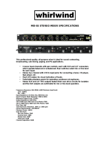
Thank you for choosing a Mackie Designs pro-
fessional compact mixer. The 1604-VLZ PRO is
equipped with our new precision-engineered
XDR
TM
Extended Dynamic Range premium
studio-grade mic preamp featuring:
• Full gain range from 0 to 60dB
• +22 dBu line signal handling capability
• 130 dB dynamic range
• Distortion less than 0.005%, 20Hz to 20kHz
• Bullet-proof RF rejection using DC pulse
transformer circuitry
• Made in Woodinville, Washington, USA
Now that you have your 1604-VLZ PRO, find
out how to get the most from it. That’s where
this manual comes in.
HOW TO USE THIS MANUAL
Since many of you folks will want to hook up
your 1604-VLZ
PRO immediately, the first pages
you will encounter after the table of contents are
the ever popular hookup diagrams. These show
typical mixer setups for Record/Mixdown, Video,
Disc Jockey and Stereo PA. After this section is a
detailed tour of the entire mixer.
Every feature of the 1604-VLZ
PRO will be
described “geographically;” in other words, in
order of where it is physically placed on the
mixer’s top or rear panel. These descriptions are
divided into the first three manual chapters, just
as your mixer is organized into three distinct
zones:
1. PATCHBAY: The zillion jacks on the back
of the “pod.”
2. CHANNEL STRIP: The sixteen channel
strips on the left.
3. OUTPUT SECTION: The output section on
the right.
Whenever a specific 1604-VLZ
PRO compo-
nent is mentioned, it’ll be in all capital letters
sans-serif type. That can help you find refer-
ences to specific controls much faster, without
slowing you down as you read normally. For ex-
ample: The quick brown fader jumped over the
RUDE SOLO LIGHT
.
Throughout these chapters you’ll find illus-
trations, with each feature numbered. If you’re
curious about a feature, simply locate it on the
appropriate illustration, note the number at-
tached to it, and find that number in the nearby
paragraphs or refer to the table of contents.
You’ll also find cross-references to these num-
bered features within a paragraph. For instance, if
you see “To wire your own cables:
,” simply find
that number in the manual and you’ve found your
answer. (These are not page numbers.)
You’ll also notice feature numbers just float-
ing in space, like this
. These numbers
direct you to relevant information.
This icon marks infor-
mation that is critically
important or unique to the
1604-VLZ
PRO. For your
own good, read them and
remember them. They will be on the final
test.
This icon will lead you to
in-depth explanations of fea-
tures and practical tips. While
not mandatory, they’ll have
some valuable information.
THE GLOSSARY: A HAVEN OF
NON-TECHINESS FOR THE NEOPHYTE
Appendix is a fairly comprehensive
dictionary of pro-audio terms. If terms like “clip-
ping,” “noise floor,” or “unbalanced” leave you
blank, flip to this glossary for a quick explanation.
A PLUG FOR THE CONNECTORS SECTION
Appendix is a section on connectors:
XLR connectors, balanced connectors, unbal-
anced connectors, special hybrid connectors.
ARCANE MYSTERIES ILLUMINATED
Appendix discusses some of the down ’n’
dirty practical realities of microphones, fixed
installations, grounding, and balanced versus
unbalanced lines. It’s a goldmine for the neo-
phyte and even the seasoned pro might learn a
thing or two.
INTRODUCTION
PATCHBAY
CHANNEL STRIPS
OUTPUT
SECTION

5
CONTENTS
PRE ............................................................... 21
5/6 SHIFT ..................................................... 21
OUTPUT SECTION DESCRIPTION ............................ 22
MAIN MIX FADER .......................................... 22
VLZ MIX ARCHITECTURE ................................ 22
SUB FADERS................................................... 22
ASSIGN TO MAIN MIX ................................... 22
TAPE IN (LEVEL) ............................................. 23
TAPE TO MAIN MIX........................................ 23
SOURCE ......................................................... 23
CTL ROOM/PHONES...................................... 23
MODE (NORMAL (AFL)/LEVEL SET (PFL)).........24
LEVEL SET LED ................................................ 24
SOLO (LEVEL) ................................................. 24
RUDE SOLO LIGHT.......................................... 24
METERS ......................................................... 25
AUX TALK ...................................................... 25
AUX SEND (MASTER) ..................................... 25
AUX SEND SOLO ............................................ 26
AUX RETURNS (LEVEL) ................................... 26
EFFECTS TO MONITOR ................................... 26
MAIN MIX TO SUBS (AUX RET 3) ................... 26
1-2/3-4 (AUX RET 3) .................................... 26
C-R/PHNS ONLY (AUX RET 4)........................ 27
RETURNS SOLO.............................................. 27
1604-VLZ
PRO MODIFICATIONS ......................... 28
1604-VLZ
PRO BLOCK DIAGRAM......................... 30
GAIN STRUCTURE DIAGRAM................................. 31
SPECIFICATIONS.................................................... 32
SERVICE INFO ....................................................... 33
APPENDIX: Glossary ............................................. 34
APPENDIX: Connections......................................... 42
APPENDIX: Balanced Lines, Phantom Powering,
Grounding and Other Arcane Mysteries .................. 46
LEVEL-SETTING PROCEDURE.................................... 3
INSTANT MIXING.................................................... 3
HOOKUP DIAGRAMS .............................................. 6
CONVERTING TO RACKMOUNT MODE .................... 9
PATCHBAY DESCRIPTION ......................................... 10
E-Z INTERFACE ............................................... 10
MIC/LINE INPUTS ON EVERY CHANNEL........... 10
MIC INPUTS ................................................... 10
PHANTOM POWER ........................................ 10
LINE INPUTS .................................................. 11
TRIM ............................................................. 11
INSERT........................................................... 11
DIRECT OUT ................................................... 11
SPLIT MONITORING ....................................... 12
AUX SEND OUTPUTS ...................................... 12
EFFECTS: SERIAL OR PARALLEL? ..................... 13
AUX RETURN INPUTS..................................... 13
SUB OUTS ...................................................... 13
C-R OUTS (CONTROL ROOM OUTPUTS) ...... 14
PHONES OUTPUT ........................................... 14
TAPE OUTPUT ................................................ 14
TAPE INPUT ................................................... 14
MAIN INSERT................................................. 15
MAIN OUTS ................................................... 15
MONO OUTPUT ............................................. 15
MONO LEVEL ................................................. 15
POWER CONNECTION .................................... 15
FUSE .............................................................. 15
POWER SWITCH ............................................ 16
POWER LED ................................................... 16
PHANTOM SWITCH........................................ 16
PHANTOM LED............................................... 16
BNC LAMP SOCKET ........................................ 16
CHANNEL STRIP DESCRIPTION .............................. 17
“U” LIKE UNITY GAIN.................................. 17
FADER ........................................................... 17
ASSIGN (1-2, 3-4, L-R).................................. 17
SOLO ............................................................. 18
–20 (SOLO) LED ............................................ 18
OL (MUTE) LED .............................................. 18
MUTE............................................................. 19
PAN ............................................................... 19
3-BAND MID-SWEEP EQ................................. 19
LOW CUT ....................................................... 20
AUX............................................................... 20

6
1604-VLZ
PRO 8-Track Tracking
8 7
6
5
4
34
567
891011
12
131415
16
21
1
23
4
R
L
R
RLR
L
R
L
R
LR
12
3
4
5
6
DIRECT OUT
BAL/UNBAL
CHANNEL INSERTSAUX RETURNS
MAIN
INSERT
C/R OUT
BAL/UNBAL
MAIN OUT
BAL/UNBAL
MONOSTEREO
PHONES
OUT
AUX SENDS
BAL/UNBAL
12
3
4
SUB OUTS
BAL/UNBAL
CHANNEL INPUTS
L
L
L
R
L
R
TAPE
OUT
TAPE
IN
16151413121110987654321
3
2
1
Guitar Effects
Drum
Machine
Keyboard, or other line-level input
Stereo EQ w/Compressor
out
in
out
in
Mono in / stereo out
Reverb
Digital Delay
Stereo Compressor
Bass Preamp
Cassette or DAT
Stereo Power Amplifier
Studio Monitors
8-track outputs
out
in
Digital
8-track
CH
1
CH
2
FULL SYMMETRY DUAL DIFFERENTIAL HIGH CURRENT DESIGN
OL
PWR
HIGH RESOLUTION
STUDIO MONITOR
ON
OFF
OL
PWR
HIGH RESOLUTION
STUDIO MONITOR
ON
OFF
HOOKUP DIAGRAMS

7
1604-VLZ
PRO Stereo P.A.
8 7
6
5
4
34
5678
91011
12
13141516
21
1
23
4
R
L
R
RLR
L
R
L
R
LR
12
3
4
5
6
CHANNEL INSERTSAUX RETURNS
MAIN
INSERT
MONOSTEREO
PHONES
OUT
12
3
4
CHANNEL INPUTS
L
L
L
R
L
R
TAPE
OUT
TAPE
IN
16151413121110987654321
3
2 1
DIRECT OUT
BAL/UNBAL
C/R OUT
BAL/UNBAL
MAIN OUT
BAL/UNBAL
AUX SENDS
BAL/UNBAL
SUB OUTS
BAL/UNBAL
Guitar Effects
Drum
Machine
Keyboard, or other line-level input
Keyboard, or other line-level input
Stereo
Power Amplifier
Right PA Speaker
Left PA Speaker
CD Player
M
u
l
t
i
t
r
a
c
k
R
e
c
o
r
d
e
r
Stereo EQ
Optional Live Recording
out
in
out
in
Stereo
Compressor
Stereo CompressorStereo Compressor
Stage Monitor Stage Monitor
Mono EQMono EQ
Mono in / stereo out
Reverb
Digital Delay
NOTE: for mono PA, use
mono output to feed FOH.
CH
1
CH
2
FULL SYMMETRY DUAL DIFFERENTIAL HIGH CURRENT DESIGN

8
1604-VLZ
PRO Video Setup
8 7
6
5
4
34
5678
91011
12
13141516
21
1
23
4
R
L
R
RLR
L
R
L
R
LR
12
3
4
5
6
CHANNEL INSERTSAUX RETURNS
MAIN
INSERT
MONOSTEREO
PHONES
OUT
12
3
4
CHANNEL INPUTS
L
L
L
R
L
R
TAPE
OUT
TAPE
IN
16151413121110987654321
3
2 1
DIRECT OUT
BAL/UNBAL
C/R OUT
BAL/UNBAL
MAIN OUT
BAL/UNBAL
AUX SENDS
BAL/UNBAL
SUB OUTS
BAL/UNBAL
Keyboard, or other line-level input
Stereo
Power Amplifier
CD Player
Stereo Compressor
Mono in / stereo out
Reverb
Digital Delay
Master
Video
Video Deck
Video Deck
Video Deck
Computer
with Audio Card
out
in
Sampler
Multi-VCR
Video Switcher
with Time Code
Interface
CH
1
CH
2
FULL SYMMETRY DUAL DIFFERENTIAL HIGH CURRENT DESIGN
Studio Monitors
OL
PWR
HIGH RESOLUTION
STUDIO MONITOR
ON
OFF
OL
PWR
HIGH RESOLUTION
STUDIO MONITOR
ON
OFF

9
CONVERTING TO RACKMOUNT MODE
Not only is the new 1604-VLZ
PRO a compact,
professional-quality tabletop mixer, it’s rack-
mountable! Its unique rotating input pod
makes this possible.
One of the things that revolutionized the compact
mixer industry was the “convertible pod” found
on the original, classic CR-1604. Using an ordi-
nary Phillips screwdriver, the mixer could be
converted from desktop mode (as it comes from
the factory) to rackmount mode.
Fear not. We wouldn’t dare take that feature out
of the New Improved 1604-VLZ
PRO. It’s still
there and still takes just a few minutes with your
trusty screwdriver. Here’s how it’s done:
1.Remove ALL the cords from the mixer —
audio, power, lamps, everything.
2.Place the mixer, face down, on a clean soft
surface, like a blanket or very large dog.
3.Remove the four screws securing the cable
cover
and set the plate aside.
4.Replace two of the screws; the ones at the pod
end of the mixer
.
5.Remove two pod-mounting screws on each
side of the mixer
.
6.Gently pull the pod away from the slots, rotate it,
and place it, tabs first, into the rackmount tabs
, located on the underside of the main chas-
sis. Be careful not to constrict or pinch any of
the ribbon or power cables.
7.Carefully install the pod-
mounting screws in their new
locations
.
8.Install the rack ears that came
with the mixer. They can be in-
stalled in either of two depths:
mixer’s surface flush with
the rack rails, like ordinary
rackmount equipment, or
mixer’s surface sunken into the
rack, to protect the knobs from
being bumped.
An optional accessory called the ROTOPOD-
VLZ is available and can be used in desktop or
rackmount installations. It will put the patchbay
jacks on the same plane as all the knobs, buttons and
faders. This is a lifesaver in applications that demand
frequent repatching, and costs a heck of a lot less than
an external patchbay, not to mention all the inter-
face and patch cords:
. Please visit your dealer
for more exciting details. Be sure to order the
“VLZ” version so you don’t end up with the one for
the classic CR-1604!
remove
screws
rackmount
tab slots
remove
plate
replace
screws
remove
screws
flush mount
rotate
pod
replace
screws
sunken

10
At the risk of stating the obvious, this is
where you plug everything in: microphones,
line-level instruments and effects, and the ulti-
mate destination for your sound: a tape
recorder, PA system, etc. A few of the features
described in this section are on top of the
mixer, but most are out back on the “pod.”
E-Z INTERFACE
Concerned about levels,
balancing, impedances, po-
larity, or other interface
goblins? Don’t be. On your
1604-VLZ
PRO, you can patch anything almost
anywhere, with nary a care. Here’s why:
• Every input and output is balanced
(except insert, phones and RCA jacks).
• Every input and output will also accept
unbalanced lines (except XLR jacks).
• Every input is designed to accept virtually
any output impedance.
• The main left and right mix outputs can
deliver 28dBu into as low as a 600 ohm load.
• All the other outputs can deliver 22dBu
into as low as a 600 ohm load.
• All the outputs are in phase with the inputs.
All we ask is that you perform the Level-Setting
Procedure
every time you patch in a new
sound source. So stop worrying and start mixing!
MIC/LINE INPUTS ON EVERY CHANNEL
The original CR-1604 had six mic/line channels
and ten line-only channels. That was fine for most
applications, but live sound users were forced to
go out and buy the XLR-10 mic input add-on
module. No more. Each and every channel on the
New Improved 1604-VLZ
PRO has the legendary
Mackie mic/line input circuit. It’s like getting a
free XLR-10 with your mixer!
MIC INPUTS
We use phantom-powered, balanced micro-
phone inputs just like the big studio mega-
consoles, for exactly the same reason: This
kind of circuit is excellent at rejecting hum
PATCHBAY DESCRIPTION
and noise. You can plug in almost any kind of
mic that has a standard XLR-type male mic
connector. Always be sure to perform the
Level-Setting Procedure
. To learn how sig-
nals are routed from these inputs:
. If you
wire your own, connect them like this:
2
2
3
1
1
SHIELD
COLD
HOT
SHIELD
COLD
HOT
3
SHIELD
COLD
HOT
3
2
1
Pin 1 = ground or shield
Pin 2 = positive (+ or hot)
Pin 3 = negative (– or cold)
Professional ribbon, dynamic, and condenser
mics will all sound excellent through these in-
puts. The 1604-VLZ
PRO’s mic inputs will handle
almost any kind of mic level you can toss at
them, without overloading.
PHANTOM POWER
Most condenser mics require phantom power,
where the mixer sends low-current DC voltage to
the mic’s electronics through the same wires
that carry audio. The 1604-VLZ
PRO’s phantom
power is globally controlled by the
PHANTOM
switch on the rear panel .
Semipro condenser mics often have batter-
ies to accomplish the same thing. “Phantom”
owes its name to an ability to be “unseen” by
dynamic mics (Shure
®
SM57/SM58, for in-
stance) that don’t need external power and
aren’t affected by it anyway.
Unless you know for cer-
tain it is safe to do so,
never plug single-ended
(unbalanced) micro-
phones, instruments or
electronic devices into the
MIC
input jacks if
the phantom power is on.
UTILISE UN FUSIBLE DE RECHANGE DE MÊME TYPE. DEBRANCHER AVANT DE REMPLACER LE FUSIBLE
4321
INSERT INSERT INSERT
LINE
INSERT
MIC 4 MIC 3 MIC 2
MIC 1
BAL
UN-
BAL
BAL
UN-
BAL
BAL
UN-
BAL
BAL
UN-
BAL
LINELINELINE
OO
+6
PHANTOM
ON
POWER
ON
120 VAC 50/60 Hz 20W
1A/250V SLO-BLO
16
15 14 13 12 11 10 9 8 7 6 5
MIC 16
INSERT
INSERT INSERT INSERT INSERT INSERT INSERT INSERT INSERT INSERT INSERT INSERT
MIC 15 MIC 14 MIC 13 MIC 12 MIC 11 MIC 10 MIC 9 MIC 8 MIC 7 MIC 6 MIC 5
SUB OUTC-R OUT
MAIN INSERT
(TIP SEND
RING RETURN)
TAPE TAPE
MAIN OUT
AUX SEND
DIRECT OUT
AUX RETURN
3
R
L
MONO
R
R
R
R
L
R
L
R
L
R
L
LLL
1
42
5
1234
31
642
753
864
1
2
BAL/UNBAL
BAL/UNBAL BAL/UNBAL
BAL/UNBAL
BAL/UNBAL BAL/UNBAL
INPUT OUTPUT
R
L
(MONO)(MONO)(MONO)
BAL
UN-
BAL
BAL
UN-
BAL
BAL
UN-
BAL
BAL
UN-
BAL
BAL
UN-
BAL
BAL
UN-
BAL
BAL
UN-
BAL
BAL
UN-
BAL
BAL
UN-
BAL
BAL
UN-
BAL
BAL
UN-
BAL
BAL
UN-
BAL
LINELINELINELINELINELINE
LINELINELINELINELINELINE
TO REDUCE THE RISK OF
FIRE REPLACE WITH SAME
TYPE FUSE AND RATING
CAUTION:
UTILISE UN FUSIBLE DE RECHANGE DE MÊME TYPE. DEBRANCHER AVANT DE REMPLACER LE FUSIBLE
CONCEIVED, DESIGNED, AND MANUFACTURED BY MACKIE DESIGNS INC • WOODINVILLE • WA • USA • MADE IN USA • FABRIQUE AU USA • COPYRIGHT ©1998 • THE FOLLOWING ARE TRADEMARKS OR REGISTERED TRADEMARKS OF MACKIE DESIGN INC.: "MACKIE", "VLZ", "XDR", AND THE "RUNNING MAN" FIGURE • US PATENT NUMBER 29/049,129
XDR
TM
EXTENDED DYNAMIC RANGE MIC PREAMPLIFIERS ARE PROPRIETARY TO MACKIE DESIGNS, INC.
X
D
R
M
I
C
P
R
E
X
D
R
M
I
C
P
R
E
X
D
R
M
I
C
P
R
E
X
D
R
M
I
C
P
R
E
X
D
R
M
I
C
P
R
E
X
D
R
M
I
C
P
R
E
X
D
R
M
I
C
P
R
E
X
D
R
M
I
C
P
R
E
X
D
R
M
I
C
P
R
E
X
D
R
M
I
C
P
R
E
X
D
R
M
I
C
P
R
E
X
D
R
M
I
C
P
R
E
X
D
R
M
I
C
P
R
E
X
D
R
M
I
C
P
R
E
X
D
R
M
I
C
P
R
E
X
D
R
M
I
C
P
R
E

11
LINE INPUTS
These
1
/
4
" jacks share circuitry (but not
phantom power) with the mic preamps. You
can use these inputs for virtually any signal
you’ll come across, from instrument levels as
low as –50dB to operating levels of –10dBV to
+4dBu, as there is 60dB of gain available via
the
TRIM
knob . Always be sure to perform
the
Level-Setting Procedure
.
To learn how signals are routed from these
inputs:
. To connect balanced lines to these
inputs, use a
1
/
4
" tip-ring-sleeve (TRS) plug,
the type found on some stereo headphones:
Tip = positive (+ or hot)
Ring = negative (– or cold)
Sleeve = shield or ground
To connect unbalanced lines to these in-
puts, use a
1
/
4
" mono (TS) phone plug or
standard instrument cable:
Tip = signal (+)
Sleeve = ground
TRIM
Yes it’s true, these controls are not located
in the patchbay section at all. They’re found
along the top row of knobs in the channel strip
section. But their purpose is so closely linked
with the
MIC
and
LINE
input jacks that we
couldn’t bear to separate them. Here’s why:
Every time you plug something into a
MIC
or
LINE
input jack, you should perform the
Level-
Setting Procedure
, and that procedure is
basically “how to use the
TRIM
knob.”
TRIM
adjusts the input sensitivity of the
MIC
and
LINE
inputs. This allows signals from
the outside world to be adjusted to optimal
internal operating levels.
Through the XLR jack (
MIC
), there will be
0dB of gain with the knob fully down, ramping
to 60dB of gain fully up.
Through the
1
/
4
" input (
LINE
), there is 15dB
of attenuation fully down and 45dB of gain fully
up, with a “
U
” (unity gain) mark at 10:00.
This 15dB of attenuation can be very handy
when you are inserting a signal that is very hot,
or you want to add a lot of EQ gain, or both.
Without this “virtual pad,” a scenario like that
might lead to channel clipping.
INSERT
These
1
/
4
" jacks are for connecting serial
effects processors such as compressors, equaliz-
ers, de-essers, or filters
. The
INSERT
point is
after the
TRIM
control, but before the channel’s
EQ
,
LOW CUT,
fader and
MUTE
controls. Insert
cables must be wired thusly:
“tip”
This plug connects to one of the
mixer’s Channel Insert jacks.
“ring”
tip
ring
sleeve
SEND to processor
RETURN from processor
(TRS plug)
Tip = send (output to effects device)
Ring = return (input from effects device)
Sleeve = common ground
Even though channels 1–8 already have
DIRECT OUT
jacks ,
INSERT
jacks can also
be used as channel direct outputs; post-
TRIM
,
pre-
LOW CUT
, and pre-
EQ
. Here’s three ways
you can use the
INSERT
jacks:
Direct out with no signal interruption to master.
Insert only to first “click.”
Channel Insert jack
Channel Insert jack
Channel Insert jack
Direct out with signal interruption to master.
Insert all the way in to the second “click.”
For use as an effects loop.
(TIP = SEND to effect, RING = RETURN from effect.)
MONO PLUG
MONO PLUG
STEREO
PLUG
DIRECT OUT
Found only on channels 1–8, these
1
/
4
" jacks
deliver the signal from the very end of the
channel path; post-
TRIM
, post-
EQ
, post-
LOW
CUT
, post-fader and post-
MUTE
. They are the
key player in “split monitoring,” making the
1604-VLZ
PRO perfect for an 8-track studio. To
wire your own cables:
.
PAN
AUX
3
1
2
EQ
5
4
6
5/6
SHIFT
PRE
TRIM
1
SOLO
L - R
3
–
4
1
–
2
OL
-
20
U
OO
+15
U
OO
+15
U
OO
+15
U
+15-15
U
+15-15
800
2k200
8k
U
+15-15
12k
HI
MID
80Hz
LOW CUT
75 Hz
18dB/OCT
LOW
10 0
U
OO
+15
1
MUTE
M
I
C
G
A
I
N
060
+15dB -45dB
-
1
0
d
B
V
LR
OO
U
SLEEVE
TIP
TIPSLEEVE
TIP
SLEEVE
SLEEVE
TIPSLEEVE
TIP
RING
RING
TIP
SLEEVERING

12
SPLIT MONITORING
With split monitoring, you use the first eight
channels for your sound sources: vocal mics,
drum mics, keyboard/synth outputs, guitar
effects outputs, that sort of thing. From there,
the channels manipulate the sound, but are
not assigned to the output section. Instead,
they’re patched from the channel’s
DIRECT
OUT
jacks to the corresponding multitrack
input (
DIRECT OUT 1
to multitrack input 1,
2 to 2, 3 to 3, etc.). The signals will now be re-
corded or pass directly through the multitrack,
depending on each track’s record-ready status.
multitrack
machine
sound sources
direct
outputs
group
outputs
1–8 9–16
The outputs of the multitrack are then
patched to the next eight
LINE
inputs on the
1604-VLZ
PRO (multitrack out 1 to
LINE
input
9, 2 to 10, 3 to 11, etc.). Aha! That’s why it says
“
TRACK 1
” next to channel 9’s fader, “
TRACK 2
”
next to channel 10, and so forth. These chan-
nels (9–16) will be assigned to the mixer’s
output section, delivering the signals to their
ultimate destination, which may be your
mixdown 2-track, your control room system,
or your headphones.
But let’s not forget that the 1604-VLZ
PRO is
a 4-bus mixer. These buses lead to the
SUB
OUTS
, and are designed to accomplish the
task of getting channels to the multitrack with-
out using the direct outputs.
For example, a channel is assigned to
SUB OUT 1
.
SUB OUT 1
’s output is patched to
multitrack input 1. From there, the multitrack
output goes to the mixer’s channel 9
LINE
input,
as we just discussed. (Hot tip: To feed an 8-track
deck with 4 sub outputs, simply use Y-cords:
SUB OUT 1
feeds tracks 1 and 5,
2
feeds 2 and
6,
3
feeds 3 and 7, and
4
feeds 4 and 8. Tracks in
record mode will accept the signal, and tracks in
safe mode will ignore the signal.)
The advantages: You can assign any channel
to any track, without repatching. You can as-
sign multiple channels to one track and control
the overall level of that subgroup
. You can’t
bounce tracks without this feature.
Perhaps the best method is to do both: Use
the
SUB OUTS
to feed multichannel submixes
(like a drum kit) to some of the tracks, and
the
DIRECT OUT
jacks to feed single-channel
signals (like bass guitar) to the other tracks.
The point is that you never listen directly to
the source channels (1–8). You listen to the
monitor channels (9–16) and they’re listening to
the multitrack that is listening to the source
channels. The main advantage is that you won’t
be forced to constantly repatch your multitrack
— just set it up and forget it. You’ll also know for
certain that the signals are indeed getting to the
multitrack, since you’re constantly listening to it.
Another method of interfacing a multitrack is
called inline monitoring, and requires a mixing
console dedicated to that, like the Mackie
8•Bus. Each of its channels is actually two chan-
nels: one carrying the mic/line sound source and
the other carrying the multitrack output.
AUX SEND OUTPUTS
These
1
/
4
" jacks usually patch to the inputs
of your parallel effects devices
or to the in-
puts of your stage monitor amps. To learn how
signals are routed to these outputs:
. To wire
your own cables:
.

13
EFFECTS: SERIAL OR PARALLEL?
You’ve heard us carelessly toss around the
terms “serial” and “parallel.” Here’s what we
mean by them:
“Serial” means that the entire signal leaves
the mixer (
INSERT
send), is routed through the
effects device, and returns to the mixer
(
INSERT
return). Examples: compressor, lim-
iter, graphic equalizer. Line-level sources can
also be patched through a serial effects device
before or after the mixer.
“Parallel” means that a portion of the signal
in the mixer is tapped off to the device (
AUX
SEND
), processed, and returned to the mixer
(
AUX RETURN
) to be mixed with the original
“dry” signal. This way, multiple channels can
all make use of the same effects device.
Examples: reverb, digital delay.
AUX RETURN INPUTS
This is where you connect the outputs of your
parallel effects devices (or extra audio sources).
They’ll accept just about any pro or semipro
effects device on the market. To learn how sig-
nals are routed from these inputs:
. To wire
your own cables:
.
Mono: If you have an effects device with a
mono output (one cord), plug that into
L
in-
put of an
AUX RETURN
and leave the right
input unplugged. That way, the signal will be
sent to both sides, magically appearing in the
center as a mono signal.
SUB OUTS
These
1
/
4
" jacks are usually patched to the in-
puts of a multitrack deck, or to secondary
amplifiers in a complex installation. To learn
how signals are routed to these outputs:
.
To wire your own cables:
.
Double Busing
How on earth do you get four jacks to
feed eight tracks? To feed an 8-track deck
with only four
SUB OUTS
, simply use four
Y-cords:
•
SUB OUT 1
feeds tracks 1 and 5
•
SUB OUT 2
feeds tracks 2 and 6
•
SUB OUT 3
feeds tracks 3 and 7
•
SUB OUT 4
feeds tracks 4 and 8
Tracks in record mode will accept the signal,
and tracks in safe mode will ignore the signal.
It’s that easy.
UTILISE UN FUSIBLE DE RECHANGE DE MÊME TYPE. DEBRANCHER AVANT DE REMPLACER LE FUSIBLE
4321
INSERT INSERT INSERT
LINE
INSERT
MIC 4 MIC 3 MIC 2
MIC 1
BAL
UN-
BAL
BAL
UN-
BAL
BAL
UN-
BAL
BAL
UN-
BAL
LINELINELINE
OO
+6
PHANTOM
ON
POWER
ON
120 VAC 50/60 Hz 20W
1A/250V SLO-BLO
16
15 14 13 12 11 10 9 8 7 6 5
MIC 16
INSERT
INSERT INSERT INSERT INSERT INSERT INSERT INSERT INSERT INSERT INSERT INSERT
MIC 15 MIC 14 MIC 13 MIC 12 MIC 11 MIC 10 MIC 9 MIC 8 MIC 7 MIC 6 MIC 5
SUB OUTC-R OUT
MAIN INSERT
(TIP SEND
RING RETURN)
TAPE TAPE
MAIN OUT
AUX SEND
DIRECT OUT
AUX RETURN
3
R
L
MONO
R
R
R
R
L
R
L
R
L
R
L
LLL
1
42
5
1234
31
642
753
864
1
2
BAL/UNBAL
BAL/UNBAL BAL/UNBAL
BAL/UNBAL
BAL/UNBAL BAL/UNBAL
INPUT OUTPUT
R
L
(MONO)(MONO)(MONO)
BAL
UN-
BAL
BAL
UN-
BAL
BAL
UN-
BAL
BAL
UN-
BAL
BAL
UN-
BAL
BAL
UN-
BAL
BAL
UN-
BAL
BAL
UN-
BAL
BAL
UN-
BAL
BAL
UN-
BAL
BAL
UN-
BAL
BAL
UN-
BAL
LINELINELINELINELINELINE
LINELINELINELINELINELINE
TO REDUCE THE RISK OF
FIRE REPLACE WITH SAME
TYPE FUSE AND RATING
CAUTION:
UTILISE UN FUSIBLE DE RECHANGE DE MÊME TYPE. DEBRANCHER AVANT DE REMPLACER LE FUSIBLE
CONCEIVED, DESIGNED, AND MANUFACTURED BY MACKIE DESIGNS INC • WOODINVILLE • WA • USA • MADE IN USA • FABRIQUE AU USA • COPYRIGHT ©1998 • THE FOLLOWING ARE TRADEMARKS OR REGISTERED TRADEMARKS OF MACKIE DESIGN INC.: "MACKIE", "VLZ", "XDR", AND THE "RUNNING MAN" FIGURE • US PATENT NUMBER 29/049,129
XDR
TM
EXTENDED DYNAMIC RANGE MIC PREAMPLIFIERS ARE PROPRIETARY TO MACKIE DESIGNS, INC.
X
D
R
M
I
C
P
R
E
X
D
R
M
I
C
P
R
E
X
D
R
M
I
C
P
R
E
X
D
R
M
I
C
P
R
E
X
D
R
M
I
C
P
R
E
X
D
R
M
I
C
P
R
E
X
D
R
M
I
C
P
R
E
X
D
R
M
I
C
P
R
E
X
D
R
M
I
C
P
R
E
X
D
R
M
I
C
P
R
E
X
D
R
M
I
C
P
R
E
X
D
R
M
I
C
P
R
E
X
D
R
M
I
C
P
R
E
X
D
R
M
I
C
P
R
E
X
D
R
M
I
C
P
R
E
X
D
R
M
I
C
P
R
E
Dry Signal
Processed
Signal
Insert
Send
Insert
Return
Dry Signal(s)
Dry Signal(s)
Aux
Send
Aux
Return
Wet Signal
Channel Path
Mix
Stage
Output
Section
Processed
Signal
Signal Processor
Signal Processor
Serial Device (e.g., Compressor)
Parallel Device (e.g., Reverb)

14
This method is exactly
the same as the double-
busing feature found in
other mixers. Built-in double
busing is nothing more than
Y-cords living inside the mixer instead of
hanging out the back. If we had room for the
extra jacks, we would have thrown them in,
but we don’t, so we didn’t. Sonically, there is
no difference whatsoever.
Y-cord advice: Do not use the stereo “head-
phone-to-left/right” splitter adapters. Use the type
that send the same signal to two places; the tip of
the source plug feeds the tips of both destination
plugs (Radio Shack
®
#42-2150, for instance.)
C-R OUTS (CONTROL ROOM OUTPUTS)
These
1
/
4
" jacks are usually patched to the
inputs of your control room amplifier or a
headphone distribution amplifier. To learn
how signals are routed to these outputs:
.
To wire your own cables:
.
PHONES OUTPUT
The 1604-VLZ
PRO’s stereo
1
/
4
" phones jack
will drive any standard headphone to very loud
levels. Walkperson-type phones can also be
used with an appropriate adapter. To learn
how signals are routed to these outputs:
. If
you’re wiring your own cable for the
PHONES
output, follow standard conventions:
Tip = left channel
Ring = right channel
Sleeve = common ground
WARNING: When we say
the headphone amp is
loud, we’re not kidding. It
can cause permanent ear
damage. Even intermedi-
ate levels may be painfully loud with some
earphones. BE CAREFUL!
Always turn the
CTL ROOM/PHONES
knob
all the way down before connecting head-
phones. Keep it down until you’ve put the
phones on. Then turn it up slowly. Why?
“Engineers who fry their ears find themselves
with short careers.”
TAPE OUTPUT
These unbalanced RCA jacks tap the
MAIN
MIX
outputs to make simultaneous recording
and PA work more convenient. Connect these
to your 2-track recorder’s inputs. To learn how
signals are routed to these outputs:
.
Mono: If you want to feed a mono signal to
your tape deck or other device, simply use the
1
/
4
"
MONO
output jack . Alternatively, use
an RCA Y-cord to combine the
TAPE OUTPUT
jacks (Radio Shack
®
#274-511, for instance).
Do not attempt this with any other outputs on
the 1604-VLZ
PRO.
TAPE INPUT
These unbalanced RCA jacks are designed
to work with semipro as well as pro recorders.
Connect your 2-track tape recorder’s outputs
here, using standard hi-fi RCA cables. To learn
how signals are routed from these inputs:
.
Use these jacks for convenient playback of
your mixes. You’ll be able to review a mix, and
then rewind and try another pass without
repatching or disturbing the mixer levels. You
can also use these jacks with a portable tape
or CD player to feed music to a PA system
between sets
.
WARNING: Pushing
TAPE
TO MAIN MIX
in the out-
put section can create a
feedback path between
TAPE INPUT
and
TAPE
OUTPUT
. Make sure your tape deck is not
in record, record-pause or input monitor
mode when you engage this switch, or
make sure the
TAPE IN
level knob is fully
counterclockwise (off).
SLEEVE
TIPSLEEVE
TIP
RING
RING
TIP
SLEEVERING
PHONES
MAIN
MIX
RIGHT
1234
LEFT
RIGHT
LEFT
RIGHT
LEFT
RIGHT
LEFT
ASSIGN TO MAIN MIX
dB
30
20
10
OO
40
50
5
5
U
60
10
dB
30
20
10
OO
40
50
5
5
U
60
10

15
MAIN INSERT
These
1
/
4
" jacks are for connecting serial
effects such as compressors, equalizers, de-
essers, or filters
. The
INSERT
point is after
the mix amps, but before the
MAIN MIX
fader.
Insert cables must be wired thusly:
“tip”
This plug connects to one of the
mixer’s Channel Insert jacks.
“ring”
tip
ring
sleeve
SEND to processor
RETURN from processor
(TRS plug)
Tip = send (output to effects device)
Ring = return (input from effects device)
Sleeve = common ground (connect shield to
all three sleeves)
MAIN OUTS
These
1
/
4
" jacks are usually patched to the
inputs of your 2-track mixdown deck (unless
you’ve chosen to use the
TAPE OUTPUT
RCA
jacks), or to the house amplifier during live
sound sessions. To learn how signals are
routed to these outputs:
. To use these out-
puts to drive balanced inputs, connect
1
/
4
" TRS
(Tip-Ring-Sleeve) phone plugs like this:
Tip = + (hot)
Ring = – (cold)
Sleeve = ground
To use these outputs to drive unbalanced
inputs, connect
1
/
4
" TS (Tip-Sleeve) phone
plugs like this:
Tip = signal
Sleeve = ground
MONO OUTPUT
It happens to everybody sooner or later:
The forces that govern your world will demand
a monaural output from your painstakingly-
created stereo panorama. The last thing you
want to do is start twirling all your carefully-
placed
PAN
settings to one side. What to do?
Stick a cord in this
1
/
4
" jack, hand the other
end to Mr. Mono, and you’re done. He’s got his
mono mix and you’ve still got your stereo mix.
The
MONO
output is nothing more than a mix
of the left and right
MAIN MIX
.
MONO LEVEL
So, Mr. Mono comes running back, scream-
ing about the mono mix being so loud that his
camcorder is melting. Just reach for this knob
and turn it down a bit. Just the thing for send-
ing mono signals to mic inputs like camcorders,
telephone interface boxes, even answering
machines. With the pot all the way up (fully
clockwise), you’ll have 6dB of extra gain with
unity gain halfway between the one and two
o’clock positions.
POWER CONNECTION
Just in case you lose the cord provided with
the 1604-VLZ
PRO, its power jack accepts a
standard 3-prong IEC cord like those found on
most professional recorders, musical instru-
ments, and computers. At the other end of our
cord is — get this — a plug! Not a black cube
or, as we’re fond of calling them, a “wall wart.”
We did this for some very good reasons:
The 1604-VLZ
PRO has sophisticated power
requirements that a wall wart cannot provide.
Wall warts are inconvenient, fragile, radiate huge
hum fields, hog extra jacks on your power strip
and get in the way. If you lose a wall wart, you’re
in trouble, but if you lose the 1604-VLZ
PRO’s
power cord, you can get a new one at any elec-
tronics, music, or computer store. You can even
buy them at Radio Shack
®
(part # 278-1257).
Plug the 1604-VLZ
PRO into any standard
grounded (3-pin) AC outlet or into a power
strip of proper voltage.
WARNING: Disconnecting
the plug’s ground pin can
be dangerous. Please
don’t do it.
FUSE
The 1604-VLZ
PRO is fused for your (and
its own) protection. If you suspect a blown
fuse, disconnect the power cord, pull the fuse
drawer out (located just below the cord re-
ceptacle) and replace the fuse with a 1A SLO
BLO, 5x20mm, available at electronics stores or
your dealer (or a 500mA [0.5 amps] SLO BLO
5x20mm if your 1604-VLZ
PRO is a 220V-240V
unit).
SLEEVE
TIPSLEEVE
TIP
RING
RING
TIP
SLEEVERING
SLEEVE
TIP
TIPSLEEVE
TIP
SLEEVE
UTILISE UN FUSIBLE DE RECHANGE DE MÊME TYPE. DEBRANCHER AVANT DE REMPLACER LE FUSIBLE
OO
+6
PHANTOM
ON
POWER
ON
120 VAC 50/60 Hz 20W
1A/250V SLO-BLO
16
15 14 13 12 11 10
MIC 16
INSERT
INSERT INSERT INSERT INSERT INSERT INSERT
MIC 15 MIC 14 MIC 13 MIC 12 MIC 11 MIC 10
C-R OUT
MAIN INSERT
(TIP SEND
RING RETURN)
TAPE TAPE
MAIN OUT
R
L
MONO
R
L
R
L
R
L
R
L
BAL/UNBAL
BAL/UNBAL
INPUT OUTPUT
BAL
UN-
BAL
BAL
UN-
BAL
BAL
UN-
BAL
BAL
UN-
BAL
BAL
UN-
BAL
BAL
UN-
BAL
BAL
UN-
BAL
LINE
LINELINELINELINELINELINE
TO REDUCE THE RISK OF
FIRE REPLACE WITH SAME
TYPE FUSE AND RATING
CAUTION:
UTILISE UN FUSIBLE DE RECHANGE DE MÊME TYPE. DEBRANCHER AVANT DE REMPLACER LE FUSIBLE
CONCEIVED, DESIGNED, AND MANUFACTURED BY MACKIE DESIGNS INC • WOODINVILLE • WA • USA • MADE IN USA • FABRIQUE AU USA • COPYRIG
XDR
TM
EXTENDED DYNA
X
D
R
M
I
C
P
R
E
X
D
R
M
I
C
P
R
E
X
D
R
M
I
C
P
R
E
X
D
R
M
I
C
P
R
E
X
D
R
M
I
C
P
R
E
X
D
R
M
I
C
P
R
E
X
D
R
M
I
C
P
R
E

16
POWER SWITCH
If this one isn’t self-explanatory, we give up.
You can leave this switch on all the time; the
1604-VLZ
PRO is conservatively designed, so
heat buildup isn’t a problem even in 24-hour-a-
day operation. There’s nothing that will burn
out or get used up. You may notice that the
1604-VLZ
PRO’s “pod” feels quite warm (the
pod is the chassis that contains the jacks).
This is perfectly normal.
POWER LED
You’ve probably already figured this out, but
if the
POWER
switch is on, this LED (light-
emitting diode), located in the output section,
will light. If the switch is off, well, you get the
idea. If the
POWER
switch is on and the LED
does not glow, one of three things has hap-
pened: Somebody tripped over the power cord
and yanked it from the outlet, your electricity
has been turned off due to nonpayment, or the
fuse has blown
.
PHANTOM SWITCH
The
PHANTOM
switch controls the phan-
tom power supply for condenser microphones as
discussed at the start of this section
. When
turned on (or off), the phantom power circuitry
takes a few moments for voltage to ramp up (or
down). This is also perfectly normal. For an
even closer look, refer to Appendix C.
PHANTOM LED
Located right next to the
POWER
LED in the
output section, this is just to let you know which
way you have the
PHANTOM
switch set. If your
dynamic mics work and your condensers don’t,
chances are this LED is off, so turn it on.
You’ll notice that when you turn the phan-
tom power off, the LED stays on for a while.
This is a natural phenomenon — the LED is
actually a yellow voltmeter telling you that the
phantom power takes time to ramp itself down
to zero volts. So, if you’ve turned phantom
power off to connect something to the mic in-
puts, wait until the yellow LED stops glowing
and then make your connections safely.
BNC LAMP SOCKET
Located in the top right corner of the out-
put section, this 12V socket will drive any
standard BNC-type lamp (a Littlite
®
#12G or
#12G-HI (high-intensity), for instance).
UTILISE UN FUSIBLE DE RECHANGE DE MÊME TYPE. DEBRANCHER AVANT DE REMPLACER LE FUSIBLE
4321
INSERT INSERT INSERT
LINE
INSERT
MIC 4 MIC 3 MIC 2
MIC 1
BAL
UN-
BAL
BAL
UN-
BAL
BAL
UN-
BAL
BAL
UN-
BAL
LINELINELINE
OO
+6
PHANTOM
ON
POWER
ON
120 VAC 50/60 Hz 20W
1A/250V SLO-BLO
16
15 14 13 12 11 10 9 8 7 6 5
MIC 16
INSERT
INSERT INSERT INSERT INSERT INSERT INSERT INSERT INSERT INSERT INSERT INSERT
MIC 15 MIC 14 MIC 13 MIC 12 MIC 11 MIC 10 MIC 9 MIC 8 MIC 7 MIC 6 MIC 5
SUB OUTC-R OUT
MAIN INSERT
(TIP SEND
RING RETURN)
TAPE TAPE
MAIN OUT
AUX SEND
DIRECT OUT
AUX RETURN
3
R
L
MONO
R
R
R
R
L
R
L
R
L
R
L
LLL
1
42
5
1234
31
642
753
864
1
2
BAL/UNBAL
BAL/UNBAL BAL/UNBAL
BAL/UNBAL
BAL/UNBAL BAL/UNBAL
INPUT OUTPUT
R
L
(MONO)(MONO)(MONO)
BAL
UN-
BAL
BAL
UN-
BAL
BAL
UN-
BAL
BAL
UN-
BAL
BAL
UN-
BAL
BAL
UN-
BAL
BAL
UN-
BAL
BAL
UN-
BAL
BAL
UN-
BAL
BAL
UN-
BAL
BAL
UN-
BAL
BAL
UN-
BAL
LINELINELINELINELINELINE
LINELINELINELINELINELINE
TO REDUCE THE RISK OF
FIRE REPLACE WITH SAME
TYPE FUSE AND RATING
CAUTION:
UTILISE UN FUSIBLE DE RECHANGE DE MÊME TYPE. DEBRANCHER AVANT DE REMPLACER LE FUSIBLE
CONCEIVED, DESIGNED, AND MANUFACTURED BY MACKIE DESIGNS INC • WOODINVILLE • WA • USA • MADE IN USA • FABRIQUE AU USA • COPYRIGHT ©1998 • THE FOLLOWING ARE TRADEMARKS OR REGISTERED TRADEMARKS OF MACKIE DESIGN INC.: "MACKIE", "VLZ", "XDR", AND THE "RUNNING MAN" FIGURE • US PATENT NUMBER 29/049,129
XDR
TM
EXTENDED DYNAMIC RANGE MIC PREAMPLIFIERS ARE PROPRIETARY TO MACKIE DESIGNS, INC.
X
D
R
M
I
C
P
R
E
X
D
R
M
I
C
P
R
E
X
D
R
M
I
C
P
R
E
X
D
R
M
I
C
P
R
E
X
D
R
M
I
C
P
R
E
X
D
R
M
I
C
P
R
E
X
D
R
M
I
C
P
R
E
X
D
R
M
I
C
P
R
E
X
D
R
M
I
C
P
R
E
X
D
R
M
I
C
P
R
E
X
D
R
M
I
C
P
R
E
X
D
R
M
I
C
P
R
E
X
D
R
M
I
C
P
R
E
X
D
R
M
I
C
P
R
E
X
D
R
M
I
C
P
R
E
X
D
R
M
I
C
P
R
E
AUX
SEND
STEREO AUX RETURN
EFFECTS TO
MONITORS
TO AUX
SEND 2
TO AUX
SEND 1
1
2
PWR
PHAN
SOLO
SOLO
1
2
1
2
3
4
1
2
C
-
R / PHNS
ONLY
RETURNS
SOLO
MAIN MIX
TO SUBS
ASSIGN OPTIONS
1
–
2
3
–
4
U
OO
+20
U
OO
+20
U
OO
+15
U
OO
+15
U
OO
+20
U
OO
+20
U
OO
+10
U
OO
+10
LEFT RIGHT
LAMP
12 V
0.5A
1604-VLZPRO
16-CHANNEL MIC / LINE MIXER
WITH PREMIUM XDR
TM
MIC PREAMPLIFIERS

17
CHANNEL STRIP DESCRIPTION
A Clean Fade
Faders are not rocket
science — they operate by
dragging a metal pin (the
wiper) across a carbon-based
strip (the track). It is possible for airborne
crud to land on the track. Should that happen,
you may hear scratchy noises or signal drop-
outs as the wiper stumbles over the crud. Do
all you can to keep airborne crud out of your
profession. Use air conditioned rooms when-
ever possible, avoid smoking near the mixer,
keep food and drink away from the mixer, and
for pity’s sake, never put the mixer in your
kitchen! We also recommend “exercising” the
faders — give them a few full-travel excur-
sions once a week or so, and that will help
scare the crud away. We do not recommend
spray cleaners.
ASSIGN (1–2, 3–4, L–R)
Alongside each channel fader are four but-
tons, labeled
SOLO
,
1–2
,
3–4
and
L–R
. The
latter three are collectively referred to as chan-
nel assignment switches.
1
,
3
and
L
are the left
sides of these stereo pairs, and
2
,
4
and
R
are
the right sides. Used in conjunction with the
channel’s
PAN
knob , these switches deter-
mine the destination of a channel’s signal:
With the
PAN
knob set at the center detent,
the left and right sides receive equal signal
levels. To feed only one side or the other, just
turn the
PAN
knob accordingly.
If you’re doing a mixdown to a 2-track, sim-
ply engage the
L–R
switch on each channel
that you want to hear, and they’ll be sent to the
MAIN MIX
. If you want to create a subgroup of
certain channels, engage either the
1–2
or
3–4
switches instead of the
L–R
, and they’ll be sent
to the appropriate subgroup faders
. From
there, the subgroups can be sent back to the
MAIN MIX
, allowing you to use the sub-
group faders as a master control for those
channels.
The sixteen channel strips look alike and
function identically. The only difference is that
the eight on the left have
DIRECT OUT
jacks
and the eight on the right don’t. We’ll start
at the bottom and work our way up.
“U” LIKE UNITY GAIN
Mackie mixers have a “
U
”
symbol on almost every level
control. This “
U
” stands for
“unity gain,” meaning no
change in signal level. Once you have per-
formed the
Level-Setting Procedure
, you
can set every control at “U” and your signals
will travel through the mixer at optimal lev-
els. What’s more, all the labels on our controls
are measured in decibels (dB), so you’ll know
what you’re doing level-wise if you choose to
change a control’s settings.
You won’t have to check it here and check it
there, as you would with some other mixers. In
fact, some don’t even have any reference to
actual dB levels at all! Ever seen those “0–10”
fader markings? We call these AUMs (Arbitrary
Units of Measurement), and they mean noth-
ing in the real world. You were smart — you
bought a Mackie.
FADER
The fader is almost the last control in a
channel’s signal path. It’s placed after the
EQ
and
MUTE
controls (post-
EQ
/post-
MUTE
and
before the
PAN
control (pre-
PAN
). The “
U
”
mark, about three-quarters of the way up,
indicates unity gain, meaning no increase or
decrease of signal level. All the way up pro-
vides an additional 10dB, should you need to
boost a section of a song. If you find that the
overall level is too quiet or too loud with a
fader near unity, you’ll want to confirm the
TRIM
setting by performing the
Level-Setting
Procedure
.
PAN
AUX
3
1
2
EQ
5
4
6
5/6
SHIFT
PRE
TRIM
1
SOLO
L - R
3
–
4
1
–
2
OL
-
20
U
OO
+15
U
OO
+15
U
OO
+15
U
+15-15
U
+15-15
800
2k200
8k
U
+15-15
12k
HI
MID
80Hz
LOW CUT
75 Hz
18dB/OCT
LOW
10 0
U
OO
+15
1
MUTE
M
I
C
G
A
I
N
060
+15dB -45dB
-
1
0
d
B
V
LR
OO
U

18
If you’re printing new tracks or bouncing ex-
isting ones, you’ll also use the
1–2
and
3–4
switches, but not the
L–R
switch. Here, you
don’t want the subgroups sent back into the
MAIN MIX
, but sent out, via the
SUB OUTS
jacks, to your multitrack inputs . However, if
you’re printing tracks via the
DIRECT OUT
jacks , all the channel assignment switches
should be disengaged (up).
The 1604-VLZ
PRO is what we call a “true
4-bus mixer.” Each channel can be assigned or
unassigned to any of the subgroups without af-
fecting the other subgroups or settings within
the channel, and each subgroup has its own
master fader
and dedicated output . In
fact, since there are 4 subgroups and the
MAIN
L–R MIX
, it’s actually a true 6-bus mixer. We
could have named it the CR1606-VLZ. Darn!
SOLO
This lovable switch allows you to check
signals through your
PHONES
output or
C-R
OUTS
without having to assign them to the
L-R
,
1-2
or
3-4
mixes. You can solo as many
channels as you like.
SOLO
does not interrupt
any of the other channels, buses or outputs —
that’s called nondestructive solo. Not only that,
via the
MODE
switch , the 1604-VLZ
PRO’s
solo system comes in two flavors:
NORMAL
(AFL)
(sometimes called SIP, or solo-in-place)
and
LEVEL SET (PFL)
(sometimes called PFL,
or pre-fader-listen).
During
NORMAL (AFL)
mode, the soloed
channel’s signal is sent directly to the
C-R OUTS
,
PHONES
output, and meter display just as it
would sound to the channel’s assignment
switches: post-
EQ
, post-fader and post-
PAN
.
The only difference is that
SOLO
works re-
gardless of the channel’s assignment positions,
and that makes it really handy — you can
check out a channel before you assign it.
NORMAL (AFL)
is the preferred mode dur-
ing mixdown: If the channel has some
midrange boost at 4.236kHz, is panned a smid-
gen to the left, and its fader is at –5.385dB,
that’s exactly what you’ll hear if you
SOLO
dur-
ing
NORMAL (AFL)
mode. It’s just as if you
took the time to
MUTE
all the other channels.
LEVEL SET (PFL)
solo is the key player in the
all-important
Level-Setting Procedure
. It’ll
send the channel’s actual internal levels to the
meters so you’ll know just what’s going on, level-
wise. This procedure should be performed every
time a new sound source is patched into a
channel’s
MIC
or
LINE
input jacks.
LEVEL SET (PFL)
is also the preferred mode
for SR (sound reinforcement, or live sound), to
preview channels before they are let into the
mix. It won’t give you stereo placement, but will
give you signal even if the fader is pulled down.
Remember,
LEVEL SET (PFL)
taps the chan-
nel signal before the fader. If you have a
channel’s fader set way below “
U
” (unity gain),
SOLO
won’t know that and will send a unity
gain signal to the
C-R OUTS
,
PHONES
output
and meter display. That may result in a startling
level boost at these outputs, depending on the
position of the
SOLO
level knob .
In a nutshell, soloed channels are sent to
the
SOURCE
mix , that ultimately feeds your
C-R OUTS
,
PHONES
output and meter display.
Whenever
SOLO
is engaged, all
SOURCE
se-
lections (
MAIN MIX
,
1–2
,
3–4
and
TAPE
) are
defeated, to allow the soloed channel to do just
that —
SOLO
!
–20 (SOLO) LED
An LED that does two completely different
things! Saves space, but requires some expla-
nation. First, the “
–20
” part: Often referred to
as “signal activity,” this LED will flicker in time
with the signal present in that channel. It’s
handy for confirming that a channel is indeed
active, and may also lend a clue as to what the
signal is. For instance, a kick drum will cause
the LED to pulse in time with the drum, and a
synth pad will cause it glow a bit more steadily.
Now for the “
SOLO
” part. When a channel’s
SOLO
switch is engaged, this LED will glow
steadily, without flickering. It will also be
brighter than it would be as a
–20
indicator. In
conjunction with the
RUDE SOLO LIGHT
,
you can find a rogue
SOLO
switch very quickly.
OL (MUTE) LED
Another LED that does two completely differ-
ent things! First, the “
OL
” part: “
OL
” means
overload, or clip. You don’t want that to happen.
Ever. Clipping can happen to any mixer — it’s
the point where the signal’s voltage exceeds the
supply voltages that power the circuitry. The
1604-VLZ
PRO’s
OL
LED will come on just be-
fore clipping, so if you see it, take immediate
action: Perform the
Level-Setting Procedure
.
If that doesn’t help, check for excessive use of
EQ
boost or
fader
gain. Like the
–20
LED, it will
tend to flicker in time with that channel’s signal.
Now for the “
MUTE
” part. Assuming your
levels are set correctly, the
OL
LED will never
PAN
AUX
3
1
2
EQ
5
4
6
5/6
SHIFT
PRE
TRIM
1
SOLO
L - R
3
–
4
1
–
2
OL
-
20
U
OO
+15
U
OO
+15
U
OO
+15
U
+15-15
U
+15-15
800
2k200
8k
U
+15-15
12k
HI
MID
80Hz
LOW CUT
75 Hz
18dB/OCT
LOW
10 0
U
OO
+15
1
MUTE
M
I
C
G
A
I
N
060
+15dB -45dB
-
1
0
d
B
V
LR
OO
U

19
CONSTANT LOUDNESS ! ! !
The 1604-VLZ
PRO’s
PAN
controls employ a de-
sign called “Constant
Loudness.” It has nothing
to do with living next to a freeway. As you turn
the
PAN
knob from left to right (thereby caus-
ing the sound to move from the left to the
center to the right), the sound will appear to
remain at the same volume (or loudness).
If you have a channel panned hard left (or
right) and reading 0dB, it must dip down about
4dB on the left (or right) when panned center.
To do otherwise, like those Brand X mixers,
would make the sound appear much louder
when panned center.
3-BAND MID-SWEEP EQ
The 1604-VLZ
PRO has a 3-band, mid-sweep
equalization:
LOW
shelving at 80Hz,
MID
sweep
peaking from 100Hz to 8kHz, and
HI
shelving at
12kHz. It’s probably all the EQ you’ll ever need!
(Shelving means that the circuitry boosts or
cuts all frequencies past the specified frequency.
For example, the 1604-VLZ
PRO’s
LOW EQ
boosts bass frequencies starting at 80Hz and
continuing down to the lowest note you never
heard. Peaking means that certain frequencies
form a “hill” around the center frequency.)
The
LOW EQ
provides up to 15dB boost or cut
at 80Hz. The circuit is flat (no boost or cut) at the
center detent position. This frequency represents
the punch in bass drums, bass guitar, fat synth
patches, and some really serious male singers.
20
Hz
100
Hz
1k
Hz
10k
Hz
20k
Hz
–15
–10
–5
0
+5
+10
+15
Used in conjunction with the
LOW CUT
switch , you can boost the
LOW EQ
without
injecting a ton of subsonic debris into the mix.
We recommend using the
LOW CUT
feature on
all channels, except low frequency signals, like
kick drums and bass guitars.
The
MID EQ
, or “midrange,” has a fixed
bandwidth of 1.5 octaves. The
MID
knob sets
the amount of boost or cut, up to 15dB, and is
effectively bypassed at then center detent. The
frequency knob sets the center frequency,
sweepable from 100Hz to 8kHz.
come on as a result of clipping. That’s pretty
boring. So, to liven things up, this LED will
glow steadily when that channel’s
MUTE
switch is engaged.
If you need a quick reference to these LEDs,
write this on the back of your hand:
name color flickering glowing
–20 (SOLO) green signal is present channel is soloed
OL (MUTE) red channel is clipping channel is muted
MUTE
Engaging a channel’s
MUTE
switch pro-
vides the same results as turning the fader all
the way down: Any channel assignment to
L-R
,
1-2
or
3-4
will be interrupted. All the post
AUX
sends will be silenced, as will the
DIRECT OUT
signals on channels
1
through
8
. And of course, that fun-loving
OL
(
MUTE
)
LED will commence to glow. The
PRE AUX
sends , channel
INSERT
send and
SOLO
(in
LEVEL SET (PFL)
mode) will continue to
function during
MUTE
.
Depending on the audio content in a chan-
nel, engaging its
MUTE
switch may cause a
slight popping sound. This is not a problem
within the mixer, and it can be avoided: Sim-
ply engage the
LOW CUT
switch on each
channel (unless its low frequency content is
vitally important, such as a kick drum or bass
guitar).
LOW CUT
eliminates subsonic de-
bris, which causes the pop, and its effect is
usually transparent.
PAN
PAN
adjusts the amount of channel signal
sent to the left versus the right outputs. Pan de-
termines the fate of the
L-R
assignment,
subgroups
1–2
and
3–4
, and the
SOLO
(in
LEVEL SET (PFL)
mode). With the
PAN
knob
hard left, the signal will feed the left
MAIN MIX
,
subgroup
1
, subgroup
3
and left
NORMAL
(AFL)
solo mode (assuming their assignment
switches are engaged). With the knob hard
right, signal feeds the right
MAIN MIX
, sub-
group
2
, subgroup
4
and right
NORMAL (AFL)
solo mode. With the
PAN
knob set somewhere
in-between left and right, the signal will be di-
vided between the left and right busses.
Stereo Sources
Your life will be easier if you follow this
standard convention: When patching stereo
sound sources to a mixer, always plug the left
signal into an “odd” channel (
1
,
3
,
5
, etc.) and
the right signal into the adjacent “even” chan-
nel (
2
,
4
,
6
, etc.). Then pan the odd channel
hard left and the even channel hard right.
PAN
AUX
3
1
2
EQ
5
4
6
5/6
SHIFT
PRE
TRIM
1
SOLO
L - R
3
–
4
1
–
2
OL
-
20
U
OO
+15
U
OO
+15
U
OO
+15
U
+15-15
U
+15-15
800
2k200
8k
U
+15-15
12k
HI
MID
80Hz
LOW CUT
75 Hz
18dB/OCT
LOW
10 0
U
OO
+15
1
MUTE
M
I
C
G
A
I
N
060
+15dB -45dB
-
1
0
d
B
V
LR
OO
U

20
20
Hz
100
Hz
1k
Hz
10k
Hz
20k
Hz
–15
–10
–5
0
+5
+10
+15
20
Hz
100
Hz
1k
Hz
10k
Hz
20k
Hz
–15
–10
–5
0
+5
+10
+15
Most of the root and lower harmonics that
define a sound are located in the 100Hz–8kHz
frequency range, and you can create drastic
changes with these two knobs. Many engineers
use
MID EQ
to cut midrange frequencies, not
boost them. One popular trick is to set the
MID
fully up, turn the frequency knob until you find
a point where it sounds just terrible, then back
the
MID
down into the cut range, causing
those terrible frequencies to disappear. Sounds
silly, but it works. Sometimes.
The
HI EQ
provides you up to 15dB boost or
cut at 12kHz, and it is also flat at the detent. Use
it to add sizzle to cymbals, an overall sense of
transparency, or an edge to keyboards, vocals, gui-
tar and bacon frying. Turn it down a little to
reduce sibilance or to mask tape hiss.
20
Hz
100
Hz
1k
Hz
10k
Hz
20k
Hz
–15
–10
–5
0
+5
+10
+15
With too much
EQ
, you can screw things up
royally. We’ve designed a lot of boost and cut
into each equalizer circuit because we know
everyone will occasionally need that. But if you
max the
EQ
on every channel, you’ll get mix
mush. Equalize subtly and use the left sides of
the knobs (cut), as well as the right (boost). If
you find yourself repeatedly using full boost or
cut, consider altering the sound source, such
as placing a mic differently, trying a different
kind of mic, changing the strings, or gargling.
LOW CUT
The
LOW CUT
switch, often referred to as a
high pass filter (all depends on how you look
at it), cuts bass frequencies below 75Hz at a
rate of 18dB per octave. This ain’t no thrown-in
dime-store filter — an 18dB per octave curve
requires an elaborate circuit. Nothing but the
best for you.
We recommend that you use
LOW CUT
on ev-
ery sound source except kick drum, bass guitar,
bassy synth patches, or recordings of earth-
quakes. These aside, there isn’t much down there
that you want to hear, and filtering it out makes
the low stuff you do want much more crisp and
tasty. Not only that, but low cut can help reduce
the possibility of feedback in live situations, and it
helps to conserve amplifier power.
With
LOW CUT
, you can safely boost
LOW
EQ
. Many times, bass shelving eq can really
benefit voices. Trouble is, adding
LOW EQ
also
boosts the subsonic debris: Stage rumble, mic
handling clunks, wind noise and breath pops.
LOW CUT
removes all that debris so you can
boost the
LOW EQ
without frying your woofer.
Here’s a frequency curve of
LOW EQ
combined
with
LOW CUT
:
20
Hz
100
Hz
1k
Hz
10k
Hz
20k
Hz
–15
–10
–5
0
+5
+10
+15
AUX 1, 2, 3, & 4
These four knobs tap a portion of each
channel’s signal, mix them together and send
them to the
AUX SEND
outputs . They are
off when turned fully down, deliver unity gain
at the center detent, and can provide up to
15dB of gain turned fully up. Chances are you’ll
never need this extra gain, but it’s nice to
know it’s there if you do.
The
AUX SEND
output are then patched to
parallel effects processor inputs
or stage
monitor amp inputs.
AUX SENDS 1
and
2
lev-
els are controlled not only by the channel’s
AUX
knobs, but also by the
AUX SEND
mas-
ter knobs
.
AUX SENDS
can also be used to generate
separate mixes for recording or “mix-minuses”
for broadcast. By using
AUX 1
or
2
in the
PRE
mode , these mix levels can be obtained in-
dependently of a channel’s fader settings.
PAN
AUX
3
1
2
EQ
5
4
6
5/6
SHIFT
PRE
TRIM
1
SOLO
L - R
3
–
4
1
–
2
OL
-
20
U
OO
+15
U
OO
+15
U
OO
+15
U
+15-15
U
+15-15
800
2k200
8k
U
+15-15
12k
HI
MID
80Hz
LOW CUT
75 Hz
18dB/OCT
LOW
10 0
U
OO
+15
1
MUTE
M
I
C
G
A
I
N
060
+15dB -45dB
-
1
0
d
B
V
LR
OO
U
/