Elation FUZE SFX User manual

Category
Floodlights
Type
User manual

Elation FUZE SFX is a professional lighting effect that combines a strobe, blinder, and wash effect into one powerful fixture. It features a bright 40W COB LED light source that produces a wide range of colors and effects. The FUZE SFX can be used to create stunning visuals for a variety of events, including concerts, stage productions, and nightclubs. With its compact size and lightweight design, it is easy to transport and set up.

Elation FUZE SFX is a professional lighting effect that combines a strobe, blinder, and wash effect into one powerful fixture. It features a bright 40W COB LED light source that produces a wide range of colors and effects. The FUZE SFX can be used to create stunning visuals for a variety of events, including concerts, stage productions, and nightclubs. With its compact size and lightweight design, it is easy to transport and set up.

FUZE SFX
user manual
2
©2021 ELATION PROFESSIONAL all rights reserved. Information, specifications, diagrams, images, and
instructions herein are subject to change without notice. ELATION PROFESSIONAL logo and identifying
product names and numbers herein are trademarks of ELATION PROFESSIONAL. Copyright protection
claimed includes all forms and matters of copyrightable materials and information now allowed by statutory or
judicial law or hereinafter granted. Product names used in this document may be trademarks or registered
trademarks of their respective companies and are hereby acknowledged. All non-ELATION brands and
product names are trademarks or registered trademarks of their respective companies.
ELATION PROFESSIONAL and all affiliated companies hereby disclaim any and all liabilities for property,
equipment, building, and electrical damages, injuries to any persons, and direct or indirect economic loss
associated with the use or reliance of any information contained within this document, and/or as a result of
the improper, unsafe, insufficient and negligent assembly, installation, rigging, and operation of this product.
Elation Professional USA | 6122 S. Eastern Ave. | Los Angeles, CA. 90040
323-582-3322 | 323-832-9142 fax | www.elationlighting.com | info@elationlighting.com
Elation Professional B.V. | Junostraat 2 | 6468 EW Kerkrade, The Netherlands
+31 45 546 85 66 | +31 45 546 85 96 fax | www.elationlighting.eu | info@elationlighting.eu
Elation Professional Mexico | AV Santa Ana 30 | Parque Industrial Lerma, Lerma, Mexico 52000
+52 (728) 282-7070
DOCUMENT VERSION
Due to additional product features and/or enhancements, an updated version of this
document may be available online. Please scan the QR Code with your mobile device or visit
www.elationlighting.com for the latest revision/update of this manual, before
installation and/or programming.
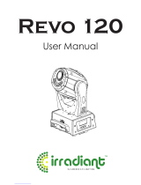
Date
Document
Version
Software
Version
DMX
Channel Modes
Notes
03/11/20 1.0 1.06 31 Channel Initial release.
05/22/20 1.1 NC No Change Updated Installation Guidelines.
07/14/20 1.2 NC No Change Updated Thermal
08/25/20 1.3 1.07 No Change Updated primary / secondary
10/14/20 1.4 NC No Change Updated specifications
05/22/21 1.5 NC No Change Updated FCC statement
3
CONTENTS
General Information
4
Warranty Returns (USA Only)
5
Safety Guidelines
6
Maintenance Guidelines
8
Fixture Overview
9
Color Wheel
10
Gobo Wheels
11
Custom Gobos
12
Gobo Installation
13
Installation Guidelines
17
System Menu
20
DMX Channel Functions and Values
27
Color Combination Table
35
Error Codes
36
Specifications
37
Dimensional Drawings
38
FCC Statement
39
4
GENERAL INFORMATION
INTRODUCTION
Please read and understand the instructions in this manual carefully and thoroughly before attempting to
operate this device. These instructions contain important safety and use information.
UNPACKING
Every device has been thoroughly tested and has been shipped in perfect operating condition. Carefully check
the shipping carton for damage that may have occurred during shipping. If the carton is damaged, carefully
inspect the device for damage, and be sure all accessories necessary to install and operate the device have
arrived intact. In the event that damage has been found or parts are missing, please contact our customer
support team for further instructions. Please do not return this device to your dealer without first contacting
customer support. Please do not discard the shipping carton in the trash. Please recycle whenever possible.
BOX CONTENTS
Fixture (x1)
Omega Brackets (x2)
Locking Power Cable (X1)
CUSTOMER SUPPORT
Contact ELATION Service for any product related service and support needs.
Also visit forums.elationlighting.com with questions, comments or suggestions.
ELATION SERVICE USA - Monday - Friday 8:00am to 4:30pm PST
323-582-3322 | Fax 323-832-9142 | support@elationlighting.com
ELATION SERVICE EUROPE - Monday - Friday 08:30 to 17:00 CET
+31 45 546 85 63 | Fax +31 45 546 85 96 | support@elationlighting.eu
REPLACEMENT PARTS please visit parts.elationlighting.com
I MPORTANT NOTICE!
THERE ARE NO USER SERVICEABLE PARTS INSIDE THIS UNIT.
DO NOT ATTEMPT ANY REPAIRS YOURSELF; DOING SO WILL VOID YOUR MANUFACTURER’S
WARRANTY. DAMAGES RESULTING FROM MODIFICATIONS TO THIS FIXTURE AND/OR THE DISREGARD
OF SAFETY INSTRUCTIONS AND GUIDELINES IN THIS MANUAL VOID THE MANUFACTURER’S WARRANTY
AND ARE NOT SUBJECT TO ANY WARRANTY CLAIMS AND/OR REPAIRS.
5
WARRANTY RETURNS (USA ONLY)
To obtain warranty service, a Return Materials Authorization (RMA) number must first be obtained from ELATION. It
is the Customers responsibility to provide product proof of purchase and serial number by acceptable evidence
such as an invoice copy or an approved ELATION Extended Warranty Certificate (“EWC”) and any relevant
maintenance records at the time warranty service is sought. Failure to provide acceptable evidence of product
proof of purchase or EWC and any relevant maintenance records may be cause for denial of warranty service.
Products returned for warranty service must be sent without any accessories (i.e., power, data, and safety cables,
brackets, clamps, rigging hardware, frost filters, gel frames, barn doors, lens, hoses, nozzles, rack mounting
hardware, etc.), must be boxed using the original and/or suitable packaging materials (double-box and foam) that
provides ample product protection for ground and/or air freight transit, and must be shipped freight pre-paid and
insured to ELATION in Los Angeles, CA or an ELATION Authorized Service Center. The RMA number must be
clearly written on the outside of the return box, and a brief description of the problem and the RMA number must
be documented and included in the box.
Products returned for warranty service without an RMA number clearly marked on the outside of the package will
be refused and returned to the shipper at the Customer’s expense. Products returned for warranty service, which
are received damaged due to inadequate and/or improper packaging and/or due to damage caused by shipping
carrier, may incur additional repair charges before warranty service begins and/or may void this warranty. If any
product accessories (included and/or optional) are shipped with the product, ELATION and/or the ELATION
Authorized Service Center shall have no liability whatsoever for the loss and/or damage to any such accessories,
nor the safe return thereof. If the requested warranty repairs or service (including parts replacement) are within the
terms of this warranty, ELATION will pay return ground transportation shipping charges to a single designated point
within the United States.
6
SAFETY GUIDELINES
This fixture is a sophisticated piece of electronic equipment. To guarantee a smooth operation, it is important
to follow all instructions and guidelines in this manual. Elation Professional is not responsible for injury and/or
damages resulting from the misuse of this fixture due to the disregard of the information printed in this manual.
Only qualified and/or certified personnel should perform installation of this fixture and only the original rigging
parts (omega brackets) included with this fixture should be used for installation. Any modifications to the fixture
and/or the included mounting hardware will void the original manufacturer’s warranty and increase the risk of
damage and/or personal injury.
PROTECTION CLASS 1 - FIXTURE MUST BE PROPERLY GROUNDED
THERE ARE NO
USER SERVICEABLE PARTS INSIDE THIS UNIT.
DO NOT ATTEMPT ANY REPAIRS YOURSELF; DOING SO WILL VOID YOUR
MANUFACTURE
R’
S WARRANTY. DAMAGES RESULTING FROM MODIFICATIONS TO
THIS FIXTURE AND/OR THE DISRE
GARD OF SAFETY INSTRUCTIONS
AND
GUIDELINES
IN THIS MANUAL VOID THE MANUFACTURER’
S WARRANTY AND ARE
NOT SUBJECT TO ANY WARRANTY CLAIMS AND/OR REPAIRS.
DO NOT PLUG FIXTURE INTO A DIMMER PACK!
NEVER OPEN THIS FIXTURE WHILE IN USE!
UNPLUG POWER BEFORE SERVICING FIXTURE!
NEVER TOUCH FIXTURE DURING OPERATION, AS IT MAY B
E HOT!
KEEP FLAMMABLE MATERIALS AWAY FROM FIXTURE!
NEVER LOOK DIRECTLY INTO THE LIGHT SOURCE!
RETINA INJURY RISK
- MAY INDUCE BLINDNESS!
SENSITIVE PERSONS MAY SUFFER AN EPILEPTIC SHOCK!
INDOOR / DRY LOCATIONS USE ONLY!
DO NOT EXPOSE FIXTURE TO RAIN AND MOI
STURE!
M
INIMUM DISTANCE TO OBJECTS/SURFACES IS 1.6 FEET (0.5 METER)
MINIMUM DISTANCE OF
INFLAMMABLE MATERIALS FROM THE SURFACE IS
1.6
FEET (0.5 METER)
MAXIMUM AMBIENT OPERATING TEMPERATURE
113°F (45°C)
7
SAFETY GUIDELINES
DO NOT TOUCH the fixture housing during operation. Turn OFF the power and allow approximately 15 minutes
for the fixture to cool down before servicing.
DO NOT shake fixture, and avoid brute force when installing and/or operating fixture.
DO NOT operate fixture if the power cord is frayed, crimped, damaged and/or if any of the power cord
connectors are damaged and do not insert into the fixture securely with ease.
NEVER force a power cord connector into the fixture. If the power cord or any of its connectors are damaged,
replace it immediately with a new one of similar power rating.
DO NOT block any air ventilation slots.
All fan and air inlets must remain clean and must never be blocked.
Allow approx. 6 (15cm) between fixture and other devices or a wall for proper cooling.
Always disconnect fixture from main power source before performing any type of service and/or cleaning. Only
handle the power cord by the plug end, and never pull out the plug by tugging the wire portion of the cord.
During the initial operation of this fixture, a light smoke or smell may emit from the interior of the fixture. This is a
normal process and is caused by excess paint in the interior of the casing burning off from the heat associated
with the lamp and will decrease gradually over time.
Consistent operational breaks will ensure fixture will function properly for many years.
O NLY use the original packaging and materials to transport the fixture for service.
8
MAINTENANCE GUIDELINES
DISCONNECT POWER BEFORE PERFORMING ANY MAINTENANCE!
CLEANING
Frequent cleaning is recommended to ensure proper function, optimized light output, and an extended life.
The frequency of cleaning depends on the environment in which the fixture operates: damp, smoky or
particularly dirty environments can cause greater accumulation of dirt on the fixture’s optics. Clean
periodically with a soft cloth to avoid dirt/debris accumulation.
NEVER use alcohol, solvents, or ammonia-based cleaners.
MAINTENANCE
Regular inspections are recommended to ensure proper function and extended life.
There are no user serviceable parts inside this fixture. Please refer all other service issues to an authorized
Elation service technician. Should you need any spare parts, please order genuine parts from an authorized
Elation dealer.
Please refer to the following points during routine inspections:
A detailed electrical check by an approved electrical engineer every three months, to make sure the
circuit contacts are in good condition and prevent overheating.
Be sure all screws and fasteners are securely tightened at all times. Loose screws may fall out during
normal operation resulting in damage or injury as larger parts could fall.
Check for any deformations on the housing, color lenses, rigging hardware and rigging points (ceiling,
suspension, trussing). Deformations in the housing could allow for dust to enter into the fixture.
Damaged rigging points or unsecured rigging could cause the fixture to fall and seriously injure a
person(s).
Electric power supply cables must not show any damage, material fatigue or sediments. NEVER
remove the ground prong from the power cable.
9
FIXTURE OVERVIEW
ALWAYS ATTACH A SAFETY
CABLE WHENEVER INSTALLING
THIS DEVICE IN A
SUSPENDED
ENVIRONMENT
TO ENSURE THE
FIXTURE WILL NOT DROP IF THE
CLAMP FAILS.
10
COLOR WHEEL
Slot Number
Color
1
Red
2
Warm Yellow
3
Medium Green
4
Orange
5
Pink
6
CTO
7
Medium Blue
11
GOBO WHEELS
12
CUSTOM GOBOS
FUZE SFX ROTATING GLASS GOBOS - WHEEL 1 ONLY
Gobo O.D. (Max. Outer Diameter)
Ф16.4mm
Gobo I.D. (Max. Image Diameter)
Ф12.5mm
Gobo Holder Diameter
Ф16.5mm
Gobo Material Borofloat Glass
* * * IMPORTANT NOTICE REGARDING CUSTOM GOBOS * * *
Due to the high temperature optical system, special material as listed above is required for custom gobos. Due to
varying manufacturing processes and tolerances, it is highly recommended to provide a gobo sample and holder
from the fixture to the custom gobo vendor for accurate sizing. Extended testing of custom gobo designs is highly
recommended prior to use. Contact ELATION SERVICE for further information.
ELATION SERVICE USA - Monday - Friday 8:00am to 4:30pm PST
323-582-3322 | Fax 323-832-9142 | support@elationlighting.com
ELATION SERVICE EUROPE - Monday - Friday 08:30 to 17:00 CET
+31 45 546 85 63 | Fax +31 45 546 85 96 | support@elationlighting.eu
13
GOBO INSTALLATION
1. Place the fixture on a stable flat surface in a DUST-FREE, INDOOR location, and ensure that the unit has
been disconnected from power and given at least 15 minutes to cool down after powering down. Engage
both the Pan Lock (location shown at above left) and the Tilt Lock (location shown at above right). For the
purposes of this procedure, we will assume that the head has been fixed in an upright position with the
lens oriented upwards.
2. Use a Phillips head screwdriver to loosen the four (4) fasteners on each of the covers. Please note that
these fasteners are of the twist-lock variety, and do not come free of the covers. Remove the safety
cable clips securing each cover to the fixture.
14
GOBO INSTALLATION
3. Optional. This step may be performed to help improve access to the gobo wheel module. On the prism
module, find the 4-pin connector (denoted by the yellow box, above right) that is located behind the left-
most electric motor, just beside the thumb screw on the left hand side of the prism module. Disconnect
this connector.
4. Optional. This step may be performed to help improve access to the gobo wheel module. Loosen the
thumb screws for the prism module, and carefully slide the prism module out of its mounting slots. Set the
prism module aside for later reinstallation.
15
GOBO INSTALLATION
5. On the gobo wheel module, locate the circuit board on the left-hand side of the gobo wheel module,
directly above the static gobo wheel. On this circuit board, find the 3-pin connector and the 4-pin connector
(denoted by the yellow boxes, above right) located just behind a bank of three (3) capacitors, and
disconnect both of these connectors.
6. Loosen the thumb screws for the gobo wheel module, and carefully slide the gobo wheel module out of
its mounting slots. Place the module on a flat, stable surface in a DUST-FREE, INDOOR location.
16
GOBO INSTALLATION
7. Locate the rotating gobo that will be replaced. Grip the edges of the geared gobo holder and gently lift
(pictured at left) until the gobo holder clears the surface of the gobo wheel. Then pull the gobo holder out
and away (pictured at right).
8. Place the gobo holder on a flat, level surface with the geared side down. Locate the tab of the spring, and
use a precision pick (or similar tool) to push the spring tab inward. Remove the retaining spring and carefully
separate the gobo from the gobo holder. Exercise caution to avoid scratching the gobo.
9. Install the new gobo and reassemble the fixture by following the steps above in reverse order.
GOBO INSTALLATION COMPLETE!
17
INSTALLATION GUIDELINES
FLAMMABLE MATERIAL WARNING
Keep fixture minimum 5.0 feet (1.5m) away from flammable materials and/or pyrotechnics.
ELECTRICAL CONNECTIONS
A qualified electrician should be used for all electrical connections and/or installations.
USE CAUTION WHEN POWER LINKING OTHER MODEL FIXTURES AS THE POWER CONSUMPTION
OF OTHER MODEL FIXTURES MAY EXCEED THE MAX POWER OUTPUT ON THIS FIXTURE. CHECK
SILK SCREEN FOR MAX AMPS.
MINIMUM DISTANCE TO OBJECTS/SURFACES
MUST BE 1 FOOT (0.3 METERS)
MINIMUM DISTANCE OF INFLAMMABLE MATERIALS
FROM THE SURFACE IS 1.6 FEET (0.5 METER)
MAXIMUM AMBIENT TEMPERATURE 113° F (45°C)
DO NOT INSTALL THE FIXTURE IF YOU ARE NOT QUALIFIED TO DO SO!
Fixture MUST be installed following all local, national, and country commercial electrical and construction
codes and regulations.
Before rigging/mounting a single fixture or multiple fixtures to any metal truss/structure or placing the fixture(s)
on any surface, a professional equipment installer MUST be consulted to determine if the metal truss/structure
or surface is properly certified to safely hold the combined weight of the fixture(s), clamps, cables, and
accessories.
Overhead rigging requires extensive experience, including amongst others calculating working load limits,
understanding of the installation material being used, and periodic safety inspection of all installation material
and the fixture. If you lack these qualifications, do not attempt the installation yourself. Improper installation can
result in bodily injury.
Fixture(s) should be installed in areas outside walking paths, seating areas, or away from areas were
unauthorized personnel might reach the fixture by hand.
NEVER stand directly below the fixture(s) when rigging, removing or servicing.
Overhead fixture installation must always be secured with a secondary safety attachment, such as an
appropriately rated safety cable.
Allow approximately 15 minutes for the fixture to cool down before servicing.
18
INSTALLATION GUIDELINES
OMEGA BRACKETS INSTALLATION
Insert the Omega Brackets into the matching holes on the bottom of the fixture. Secure the Omega Brackets
to the fixture by turning each quick-lock fastener ¼ turn clockwise; making sure the fastener is completely
locked. Omega Brackets can be installed into the fixture base as illustrated below.
CLAMP INSTALLATION
When mounting fixture to truss, be sure to secure an appropriately rated professional grade rigging clamp to
the included Omega Brackets using an M10 screw fitted through the center hole of the Omega Brackets. The
fixture provides a built-in rigging points for a SAFETY CABLE. Be sure to only use one of the designated rigging
points for the safety cable and never secure a safety cable to a carrying handle.
RIGGING
Overhead rigging requires extensive experience, including calculating working load limits, understanding of the
installation material being used, and periodic safety inspection of all installation material and the fixture, among
other things. If you lack these qualifications, do not attempt the installation yourself. Improper installation can
result in bodily injury.
ALWAYS ATTACH AN APPROPRIATELY RATED SAFETY CABLE (NOT INCLUDED) THAT MEETS ALL
LOCAL, NATIONAL, AND COUNTRY CODES AND REGULATIONS WHENEVER INSTALLING FIXTURE IN A
SUSPENDED ENVIRONMENT!
19
INSTALLATION GUIDELINES
FIXTURE MOUNTING POSITION
The fixture may be mounted in any position in which the base of the fixture is oriented horizontally. Acceptable
positions include standing the fixture upright or hanging the fixture upside-down.
Do NOT install the fixture in a sideways position, or in any position in which the base of the fixture is oriented
vertically or at an angle.
POTENTIAL INTERNAL FIXTURE DAMAGE FROM EXTERNAL SOURCES OF LIGHT BEAMS
External sources of light beams from direct sunlight, lighting moving
head fixtures, and lasers, which are focused directly towards the exterior
housing and/or penetrate the front lens opening of ELATION lighting
fixtures, can cause severe internal damage including burning to optics,
dichroic color filters, glass and metal gobos, prisms, animation wheels,
frost filters, iris, shutters, motors, belts, wiring, discharge lamps, and
LEDs.
This issue is not specific to ELATION lighting fixtures; rather, it is a
common issue with lighting fixtures from all manufacturers. Although
there is no true way to fully prevent this issue from occurring, the
guidelines below can help minimize the risk of potential damage if
followed. Contact ELATION Service for more details.
DO NOT EXPOSE THE FIXTURE AND/OR FRONT LENS OPENING TO LIGHT BEAMS FROM
DIRECT SUNLIGHT, OTHER LIGHTING MOVING HEAD FIXTURES, AND LASERS DURING
UNPACKING, INSTALLATION, USE, AND EXTENDED IDLE TIMES OUTDOORS. DO NOT
FOCUS A LIGHT BEAM FROM ONE LIGHTING FIXTURE DIRECTLY TOWARDS ANOTHER.
20
SYSTEM MENU
The fixture includes an easy to navigate system menu. The LCD touch panel display located on the front of
the fixture (see image below), provides access to the main system menu and is where all necessary system
adjustments are made to the fixture. During normal operation, pressing the ENTER (Check Mark) button once
will access the fixture’s main menu. Once in the main menu you can navigate through the different functions
and access the sub-menus with the UP and DOWN buttons. Once you reach a field that requires adjusting,
press the ENTER button to activate that field and use the UP and DOWN buttons to adjust the field. Pressing
the ENTER button once more will confirm your setting. You may exit the main menu at any time without making
any adjustments by pressing the ESC (Back Arrow) button.
To access the LCD Menu Control Display via the internal battery, press and hold the BATTERY ICON button
for 3 seconds. The LCD Menu Control Display will shut OFF automatically about 1 minute from the last button
press.
FUZE
SFX
  • Page 1 1
  • Page 2 2
  • Page 3 3
  • Page 4 4
  • Page 5 5
  • Page 6 6
  • Page 7 7
  • Page 8 8
  • Page 9 9
  • Page 10 10
  • Page 11 11
  • Page 12 12
  • Page 13 13
  • Page 14 14
  • Page 15 15
  • Page 16 16
  • Page 17 17
  • Page 18 18
  • Page 19 19
  • Page 20 20
  • Page 21 21
  • Page 22 22
  • Page 23 23
  • Page 24 24
  • Page 25 25
  • Page 26 26
  • Page 27 27
  • Page 28 28
  • Page 29 29
  • Page 30 30
  • Page 31 31
  • Page 32 32
  • Page 33 33
  • Page 34 34
  • Page 35 35
  • Page 36 36
  • Page 37 37
  • Page 38 38
  • Page 39 39
  • Page 40 40

Elation FUZE SFX User manual

Category
Floodlights
Type
User manual

Elation FUZE SFX is a professional lighting effect that combines a strobe, blinder, and wash effect into one powerful fixture. It features a bright 40W COB LED light source that produces a wide range of colors and effects. The FUZE SFX can be used to create stunning visuals for a variety of events, including concerts, stage productions, and nightclubs. With its compact size and lightweight design, it is easy to transport and set up.

Ask a question and I''ll find the answer in the document

Finding information in a document is now easier with AI