Noblelift RT16P Service Maintenance Manual
- Type
- Service Maintenance Manual

Version 12/2019
RTXXP-SMS-001-EN
Service & Maintenance Manual
Electric Reach Truck
RT16P/RT20P
WARNING
Do not use the reach truck before reading and
understanding these operating instructions.
NOTE:
• Please check the designation of your
present type at the last page of this
document as well as on the ID-plate.
• Keep it for future reference.
Scan it,
For more information
Service Hotline: 4008-836115

1
FOREWORD
Before operating the truck, read this ORIGINAL INSTRUCTION HANDBOOK carefully and understand
the usage of the truck completely. Improper operation could create danger.
This handbook describes the usage of different electric pallet trucks. When operating and servicing the
truck, make sure, that it applies to your type.
Keep this handbook for future reference. If this or the warning/ caution labels are damaged or got lost,
please contact your local dealer for replacement.
This truck complies with the requirements according to EN 3691-1 (Industrial trucks- safety requirements
and verification, part 1), EN 12895 (Industrial trucks- electromagnetic compatibility), EN 12053 (Safety of
industrial trucks- test methods for measuring noise emissions), EN 1175-1 (Industrial truck safety –
electrical requirements), assumed the truck is used according to the described purpose.
The noise level for this machine is 70 dB(A) according to EN 12053.
ATTENTION:
• Environmentally hazardous waste, such as batteries, oil and electronics, will have a negative effect
on the environment, or health, if handled incorrectly.
• The waste packages should be sorted and put into solid dustbins according to the materials and be
collected disposal by local special environment protection bureau. To avoid pollution, it’s forbidden to
throw away the wastes randomly.
• To avoid leaking during the use of the products, the user should prepare some absorbable materials
(scraps of wooden or dry duster cloth) to absorb the leaking oil in time. To avoid second pollution to
the environment, the used absorbable materials should be handed in to special departments in terms
of local authorities.
• Our products are subject to ongoing developments. Because this handbook is only for the purpose of
operating /servicing the pallet truck, therefore please have understanding, that there is no guarantee
out of particular features out of this handbook.
NOTE: On this manual, the left sign means warning and danger, which can lead to death or
serious injury if not followed.
Copyright
The copyright remains with the company, mentioned on the CE- certificate at the end of this document or,
if sold within the USA, with the company, mentioned on the company sticker.

2
TABLE OF CONTENTS
1. CORRECT APPLICATION ................................................................................................................ 4
2. DESCRIPTION OF THE REACH TRUCK ........................................................................................ 5
a. Overview of the main components .................................................................................................. 5
b. Main technical data ......................................................................................................................... 7
c. Description of the safety devices and warning labels (Europe and other, excepting USA) ........... 11
d. Identification plate (ID-plate) ......................................................................................................... 11
3. WARNINGS, RESIDUAL RISK AND SAFETY INSTRUCTIONS .................................................... 11
4. COMMISSIONING, TRANSPORTING, DECOMMISSIONING ........................................................ 12
a. Commissioning .............................................................................................................................. 12
b. Loading and unloading/ transporting ............................................................................................. 13
C. Decommisioning ............................................................................................................................. 15
5. REGULAR INSPECTION ............................................................................................................... 15
6. OPERATIONAL INSTRUCTIONS ................................................................................................... 16
a. Operational control devices position ........................................................................................ 16
b. Power-on operation ..................................................................................................................... 17
c. Travelling ........................................................................................................................................ 17
d. Steering ......................................................................................................................................... 17
e. Braking .......................................................................................................................................... 18
f. Load curve diagram ...................................................................................................................... 18
g. Lifting ............................................................................................................................................. 18
h. Lowering ........................................................................................................................................ 19
i. Mast front shift and back shift ........................................................................................................ 19
j. Fork left shift and right shift ........................................................................................................... 19
k. Fork tilts ......................................................................................................................................... 19
l. Malfunctions .................................................................................................................................. 19
m. Emergency .................................................................................................................................... 20
7. BATTERY CHANGES AND REPLACEMENT ................................................................................. 20
a. Battery replacement ...................................................................................................................... 21
b. Battery indicator and alarm ........................................................................................................... 21
c. Charging ........................................................................................................................................ 22
8. REGULAR MAINTENANCE ........................................................................................................... 22
a. Maintenance checklist ................................................................................................................... 23
b. Lubricating points .......................................................................................................................... 24
c. Check and refill hydraulic oil .......................................................................................................... 25
d. Checking electrical fuses ............................................................................................................... 26
9. TROUBLE SHOOTING ................................................................................................................... 26
10. WIRING/CIRCUIT DIAGRAM ......................................................................................................... 28

3
a. Hydraulic circuit ............................................................................................................................. 30
11. DIAGNOSTICS AND TROUBLESHOOTING .................................................................................. 31
12. SPECIALIZED STIPULATION FOR THE US - AMERICAN MARKET ......................................... 47
[GB] CE Declaration of Conformity ......................................................................................................... 47

4
1. CORRECT APPLICATION
To ensure the safety of personal and equipment, drivers shall observe the following precautions:
1. Only drivers who have been trained and hold a forklift driving license can drive;
2. The forklift is suitable for hard and flat indoors floor;
3. Check the control and alarm devices before driving the forklift. If any damage or defect is found, it
shall be operated after repair;
4. During handling, the load shall not exceed the specified value. Both forks shall be inserted under the
goods and evenly placed on the forks. Off-load is prohibited and single fork is not allowed to pick up
objects;
5. Start, veer, drive, brake and stop slowly and smoothly. Slow down when turning on wet or smooth
floors;
6. When drive the forklift with goods, lower the goods as low as possible and the fork should be tilted
backward;
7. Be careful when drive on the ramp: go forward on the uphill, go backward on the downhill, avoid
veer on the uphill or downhill;
8. When drive the forklift, pay attention to pedestrians, obstacles and potholes, and pay attention to the
clearance above the forklift;
9. No one is allowed to stand on forks or forklift;
10. No one is allowed to stand under or walk under the elevated part of the forklift;
11. Only operate the forklift from the driver's position;
12. Do not handle unsecured or loosely packed goods, and handle large goods with care;
13. When drive in the goods shelf area, drive slowly, move straight in and straight out, when the fork is
not completely removed from the shelf, no veer operation to avoid collision.
14. For the high lift forklift, try to make the mast stand lean back, and the loading and unloading
operation should be done in the minimum range;
15. Immediately stop to using when the forklift failure occurs, and the label shall be clearly indicated;
16. Lower the fork to the ground when leave the forklift, park the forklift on the horizontal ground, turn off
the power and pull out the key.
It is only allowed to use this electric reach truck according to this instruction handbook.
The capacity is marked on capacity sticker as well on the Identification plate. The operator has to
consider the warnings and safety instructions.
Operating lighting must be minimum 50 Lux.
Modification
No modifications or alterations to this pallet truck which may affect, for example, capacity, stability or
safety requirements of the truck, shall be made without the prior written approval of the original truck
manufacturer, its authorized representative, or a successor thereof. This includes changes affecting, for
example braking, steering, visibility and the addition of removable attachments. When the manufacturer
or its successor approve a modification or alteration, they shall also make and approve appropriate
changes to capacity plate, decals, tags and operation and maintenance handbooks.
Only in the event that the truck manufacturer is no longer in business and there is no successor in the interest to the business, may the
user arrange for a modification or alteration to a powered industrial truck, provided, however, that the user:
a) arranges for the modification or alteration to be designed, tested and implemented by an engineer(s) expert in industrial trucks and
their safety,
b) maintains a permanent record of the design, test(s) and implementation of the modification or alteration,
c) approves and makes appropriate changes to the capacity plate(s), decals, tags and instruction handbook, and
d) affixes a permanent and readily visible label to the truck stating the manner in which the truck has been modified or altered, together
with the date of the modification or alteration and the name and address of the organization that accomplished those tasks.
By not observing these instructions, the warranty becomes void.

5
2. DESCRIPTION OF THE REACH TRUCK
a. Overview of the main components
123
4
5
6
7
8
9
10
1112
1314
15 16
17
18
19
20
21
22
23 2425
Fig. 1: Overview main components
1. Seat assembly
2. Accelerator pedal
3. Brake pedal
4. Safety pedal switch
5. Control unit
6. Steering control
7. Key switch
8. Display
9. Overhead guard
10. Mast
11. Left and right moving control stick
12. Lifting and lowering control stick
13. Mast moving control stick
14. Mast tilting control stick
15. Signal lamp switch
16. Horn button
17. Brake switch
18. Direction control button
19. Elbow pad
20. Adjusting handle
21. Emergency button
22. Lamp switch
23. Fork arm
24. Load roller

b. Main technical data
α
β
Fig 2: Structure schematic drawing

8
Table 1: Main technical data for standard version
Type sheet for industrial truck acc. to (VDI2198)
Distinguishing mark
1.2
Manufacturer`s type designation
RT16P
RT20P
1.3
Power(battery,diesel, petrol gas,manual)
Battery
1.4
Operator type
Sit-on
1.5
Load Capacity / rated load
Q (t)
1.6
2.0
2.0
1.6
Load centre distance
c (mm)
600
600
600
1.8
Load distance, centre of drive axle to fork
x (mm)
365
395
405*
1.9
Wheelbase
y (mm)
1400
1500
1600*
Weight
2.1
Service weight (with battery)
kg
3960
4200
4800*
Tires
3.1
Tires
Polyurethane (PU)
3.2
Tire size, front
xW
(mm)
343×140
343×140
400×160*
3.3
Tire size, rear
xW
(mm)
280×110
330×110
330×140*
3.5
Wheels, number front/ rear(x=driven
wheels)
2/1x
2/1x
2/1x
3.7
Tread, front/rear
b11 (mm)
1160
1160
1290*
Dimensions
4.1
Tilt of fork carriage forward/backward
α/β (°)
4°/-2°
4°/-2°
4°/-2°
4.2
Lowered mast height
h1(mm)
3900
3900
4900*
4.3
Free lift height
h2(mm)
3290
3290
4290*
4.4
Maximum lift height
h3(mm)
9500
9500
12500*
4.5
Extended mast height
h4(mm)
10410
10410
13410*
4.7
Overhead guard height
h6(mm)
2200
2200
2200
4.19
Overall length
l1(mm)
2410
2490
2580*
4.20
Length to face of forks
l2 (mm)
1260
1340
1430*
4.21
Overall width
b1 (mm)
1270
1270
1430*
4.22
Fork dimensions
s/e/l (mm)
40/120/1150
40/120/1150
40/120/1150
4.25
Distance between fork arms(min./max.)
b5 (mm)
240/760
240/760
240/760
4.28
Reach distance
l4(mm)
525
595
640*
4.31
Minimum ground clearance
m1(mm)
75
75
75
4.33
Aisle width for fork carriage 1000X1200
cross ways
Ast (mm)
2720
2840
2880*
4.34
Aisle width for fork carriage 800X1200
lengthways
Ast (mm)
2780
2900
2980*
4.35
Turning radius
Wa (mm)
1650
1750
1840*
4.37
Distance to the rotor arm front end
l7(mm)
1780
1900
2000*

9
Performance
5.1
Travel speed, laden/ unladen
km/h
10.5/10.5
10.5/10.5
10.5/10.5
5.2
Lift speed, laden/ unladen
m/s
0.35/0.50
0.35/0.50
0.35/0.50
5.3
Lower speed, laden / unladen
m/s
0.45/0.45
0.45/0.45
0.45/0.45
5.4
Reach speed, laden / unladen
m/s
0.10/0.10
0.10/0.10
0.10/0.10
5.8
Maximum grade ability, laden/ unladen
%
10/15
10/15
10/15
5.10
Service brake
Hydraulic brake
Motors
6.1
Drive motor rating S2 60min
kW
6.4
6.4
7
6.2
Lift motor rating at S3 15%
kW
12.5
12.5
12.5
6.3
Battery acc. to DIN 43531/ 35/ 36 A, B, C
A,3Pzs
A,4Pzs
A,5Pzs
6.4
Battery voltage, nominal capacity K5
V/ Ah
48/420
48/560
48/700*
6.5
Battery weight
kg
750
950
1150*
Additional data
8.1
Type of drive control
Three-phase AC
8.2
System pressure
(bar)
150
150
150
8.3
System flow
(l/min)
40
40
42
8.4
Sound level at driver’s ear acc. to EN
12053
dB(A)
<70
<70
<70
Attention: Data with “*” mark is for 6 trucks with max lifting height of 10, 10.5, 11, 11.5, 12, 12.5 m.

10
Mast Table RT 16P
Designation
Lift height
h3 mm
Free lift height
h2 mm
Lowered mast
height h1 mm
Extended mast
height h4 mm
Two stage mast
standard lift
3000
140
2100
3910
3500
140
2350
4410
4000
140
2600
4910
4500
140
2850
5410
Three stage mast
FFL (Full Free
Lift)
4500
1563
2235
5410
5000
1730
2400
5910
5500
1897
2568
6410
6000
2063
2735
6910
6500
2230
2900
7410
7000
2397
3068
7910
7500
2563
3234
8410
8000
2730
3400
8910
8500
2897
3567
9410
9000
3063
3734
9910
9500
3230
3900
10410
Mast Table RT 20P
Two stage mast
standard lift
3000
140
2100
3910
3500
140
2350
4410
4000
140
2600
4910
4500
140
2850
5410
Three stage mast
FFL (Full Free
Lift)
4500
1563
2235
5410
5000
1730
2400
5910
5500
1897
2568
6410
6000
2063
2735
6910
6500
2230
2900
7410
7000
2397
3068
7910
7500
2563
3234
8410
8000
2730
3400
8910
8500
2897
3567
9410
9000
3063
3734
9910
9500
3230
3900
10410
10000
3397
4067
10910
10500
3563
4234
11410
11000
3730
4400
11910
11500
3897
4567
12410
12000
4063
4733
12910
12500
4230
4900
13410

11
c. Description of the safety devices and warning labels (Europe and
other, excepting USA)
Warning labels:
kg
前 移 式 叉 车
额 定 载 荷 重 量
自 重
最大起升高度
制造日期
V
kg
额 定 电 压
产品 编 号
型 号 kg
kg
kg
mm
最大蓄电池 重量 最小蓄电池重量
特 种 设 备 制 造 许 可 证 编 号 : TS 2 51 0 35 0 -2 0 21
诺 力智 能 装 备股 份 有 限 公 司 /浙 江 省 长 兴 县太 湖 街道 中 央 大 道 18 88 号
无载无蓄电 池重量
X XX X
XX X
XX X
XX XXX
X XX X
XX X XX X
X X X
Tel : 40 0 8—8 3 61 1 5
设备 代 码
本车仅限 在 工厂厂 区、 旅 游景区 、游 乐 场所使 用
工厂 货 号
A
B
C
D
E
F
A
G
G
H
I
J
K
A
Fig 3: Warning labels
A. Crane hook label: The place for allowed crane.
B. Warning label: Do not stand under or on the fork, otherwise it may cause injury.
C. Warning label: Do not stand inside mast or reach your hand inside, otherwise it may cause injury.
D. Model sticker: Indicate the type of the truck.
E. Identification plate (ID-plate): Indicate the basic information of truck, such as specification,
production date, product number, etc.
F. Nipping Hand warning label: There is a risk of hand injury at this position.
G. Fork loading label: The fork insertion position during loading.
H. Filling sticker: Hydraulic oil should be added at this position.

12
I. Seat belt sticker: Seat belt should be fastened when driving.
J. Reading warning label: Read and follow service manual.
K. Logo sticker
Safety devices
Fig 4: Safety devices
Emergency button: Please press this button immediately to cut of the power supply when the truck is
out of control, all lifting-, lowering-functions will be stopped.
Drive key switch: To prevent against unauthorized access, turn the key counterclockwise and pull it out.

11
Brake: To stop the truck when it is driving.
Tip over protection: To reduce the risk of side tip over of the truck. It’s forbidden to remove the
protection.
Pedal switch: Operate the truck with left foot on the foot pedal switch, otherwise it will be failed.
Attention: Emergency button, drive key switch, brake, rollover protection, pedal switch and hydraulic
circuit explosion-proof valve are safety devices of the truck. Safety devices and labels above must be
kept in good condition, please replace in time in case of damage or absence.
d. Identification plate (ID-plate)
Reach Truck
Special Equipment Manufacturing License No. TS2510350-2021 Tel: 4008-836115
Type
xxxx
Rated Capacity
xxxx kg
Nominal Voltage
xx V
Self Weight
xxxx kg
Max Battery Weight
xxx kg
Min Battery Weight
xxx kg
Own Mass without Battery
xxx kg
Max Lifting Height
xxxx mm
Serial Number
Manufacturing Date
Device Code
Manufacturer Art.No
This truck is only used in factories, tourist attractions and tourist sites.
Noblelift Intelligent equipment co. LTD
No.528 Changzhou Road, Taihu Sub-district, Changxing County, Zhejiang Province,China
3. WARNINGS, RESIDUAL RISK AND SAFETY INSTRUCTIONS
⚫ Do not use truck in environments with explosive gas, explosive dust or acid and alkali corrosion;
⚫ Do not use truck in the environment with poor outdoor or ground conditions;
⚫ Do not put feet or hands under or inside the lifting mechanism;
⚫ Do not stand in front or behind the truck while driving or lifting/lowering;
⚫ Do not overload, the load weight and lifting height must meet load curve requirements;
⚫ Do not put foot outside the truck when driving which may cause injuries;
⚫ Do not lift people may which may cause people falling down and severe injury suffering;
⚫ Do not push or pull goods;
⚫ Do not drive the truck on slopes;
⚫ Do not use truck with unstable, loose or unbalanced load, gravity center must be between two forks;
⚫ To prevent against unauthorized access, park the truck, turn off the power and pull out the key;
⚫ Do not make any truck modification without written consent from manufacturer;
⚫ Do not lift the cargo in the case of wind. Lifting will be unstable under the wind influence.
Watch difference in floor levels when driving. Load could fall down or the truck could get uncontrollable.
Keep watching the condition of load. Stop operating the truck if load becomes unstable.
Brake the truck and activate the emergency button by pushing when sliding load on or off the truck. If the
truck has any malfunctions, follow chapter 8.
Fig 5: Identification plate

12
• The truck is intended to be used on hard and flat ground indoors whose roughness
should be within 1cm/m2;
• The operator should hold driving license and have been trained;
• When operating the truck, the operator has to wear safety shoes.
• The truck is intended to be used with ambient temperatures between +5C~+40C;
• The operating lighting must be minimum 50 Lux.
4. COMMISSIONING, TRANSPORTING, DECOMMISSIONING
a. Commissioning
After receiving our new reach truck or for re-commissioning you have to do following before (firstly)
operating the truck:
• Check if all parts are included and not damaged
• Mast installation (please follow the instructions to install mast);
• Do the work according to the daily inspections as well as functional checks.
• Check battery installation and charge instructions (follow chapter 7).
Mast assembling:
Mast assembling required equipment:
Lifting equipment:
Driving ( 5 tons maximum load ) or fork lifting ( 3 tons load capacity and 4.5 m lifting height)
Assistant tools: S24 wrench, crowbar.
Safety precautions:
Assembling operators must take appropriate training or be trained by professional personnel on-site to
guide the assembling operation.
Operators for lifting equipment must get appropriate operating qualifications.
If the truck is directly forked on the crossbeam of the gantry, the gantry must be tied together with the
protection rope to avoid the danger of slipping.

13
Fig 6: Mast assembling diagram
Table 2: Truck carriage weight and mast weight
Type
RT16P
RT20P
Truck carriage pack weight [kg]
2300
3000
Truck carriage pack size [mm]
1800x1300X2200
2000x1300X2200
Lift height H3 [mm]
5500
7500
9500
10500
11500
12500
Mast pack weight [kg]
1240
1420
1600
1690
1790
1890
Mast pack size [mm]
3900x1000
X700
3900x1000
X700
3900x1000
X700
2400x1400
x 2700
3900x1000
X700
4900x1000
X700
b. Loading and unloading/ transporting
When load and unload the truck, refer to the guide diagram below. The weight for chasis and mast is
shown in table 2, for the whole truck weight, please the ID plate.

14
Truck carriage lift Whole truck lift Whole truck lift fork position
Fig 7: Loading and unloading guide diagram
Loading and unloading
USE DEDICATED CRANE AND LIFTING EQUIPMENT.
DO NOT STAND UNDER THE SWAYING LOAD.
DO NOT WALK INTO THE HAZARDOUS AREA DURING LIFTING.
PLACE THE TRUCK ON A LEVEL GROUND.
Transporting
DURING TRANSPORTATION ON A LORRY OR TRUCK, ALWAYS FASTEN THE
TRUCK SECURELY.
Lower the forks and park the truck securely.
Fasten the truck according to Fig. 8, put the wood blocks under the driving cab to prevent damage
to the driving wheel in transporting.

15
Fig 8: Fixing points
C. Decommisioning
Lower the fork to the lowest position, put the wood blocks under the driving cab to prevent damage to the
driving wheel as it shown in Fig.8 for long time storage.
Grease all greasing points mentioned in this handbook (regular inspection), and eventually protect the
truck against corrosion and dust.
Charge the truck of long storage every month to prevent damage on battery.
For final decommissioning hand the truck to a designated recycling company. Oil, batteries and electric
components must be recycled due to legal regulations.
5. REGULAR INSPECTION
This chapter describes pre-shift checks before putting the truck into operation.
Regular inspection is effective to find the malfunction or fault on this truck. Check the truck on the
following points before operation.
Remove load from truck and lower the forks.
DO NOT USE THE TRUCK IF ANY MALFUNCTION IS FOUND.
• Check for scratches, deformation or cracks.
• Check if there is any oil leakage from the cylinder.
• Check the function of driving in both directions
• Check the chain and rollers are without damage or corrosion.
• Check the smooth movement of the wheels.
• Check the function of the emergency brake by activating the emergency button.
• Check the functions of foot brake.
• Check the lifting and lowering functions.
• Check the seat is assembled tightly.

16
• Check the function of horn.
• Check if all bolts and nuts are tightened firmly.
• Check the function of key switch.
• Check the function of speed limitation.
• Visual check if there are any broken electric wires.
• If supplied with a backrest extension, check it for damages and correct assembling.
6. OPERATIONAL INSTRUCTIONS
a. Operational control devices position
1
2
3
4
5
6
11
12
13
97 8
14
10
15
Fig. 9: Operational control devices position

17
b. Power-on operation
Before operating the truck, make sure that the load is stable and will not cause poor
visibility.
Pull the emergency button (1), insert the key switch (2), and turn it clockwise to the
"ON" position, then step on the safety switch (6). Before start the truck, please press
the horn button (11) to start the horn to warn others if necessary. The truck is power on.
Note: please set the direction switch in the middle before power-on operation,
otherwise the operation sequence fault will be reported.
c. Travelling
After starting the truck by turning the inserted key to the “ON” position, firstly step the
safety pedal switch (6), then put your hand on the operating area. Put the switch on the
forward or backward direction, and there is arrow which means forward or backward on
the indicator, just touch it. Control the travelling speed by moving the accelerator pedal
(4) carefully until you reached the desired speed. The speed will be slower if you
release the accelerator pedal, control the speed to ensure safety. If you need sharp
slowdown, please stamp the brake pedal(5).
Drive carefully the truck to the destination. Watch the route conditions and adjust the
travelling speed with the accelerator button.
This truck is equipped with enough safety equipment to avoid accidents. When the
height of the fork is higher than the free lifting height, the speed of the truck will be
reduced to achieve smooth walking and safe work. When the fork lower below the free
lifting height, the lower the fork height, slower the truck.
Please keep the lifting height of the fork below 0.5 m when you need to travel over a
longer distance.
Please drive the truck to the safe storage area and lower the fork to the lowest position
after every use. Turn the key counterclockwise to the "close" position and pull out the
key.
Attention: Turn on the power supply, the system will start self inspection. If there is
something wrong with the electrical system, such as open circuit, short circuit, or button
on the active state, and you stamp the pedal switch, speed controller will not in the
neutral position, and the truck will not drive and report default, only when the electrical
system is OK, the truck will start normal work.
d. Steering
THE TRUCK IS EQUIPPED WITH AN ELECTRIC STEERING SYSTEM. TAKE CARE BY

18
OPERATING A TRUCK WITH THIS KIND OF SYSTEM
You steer the truck by turning the aiming circle clock wise and anti-clock wise. Turn the
aiming circle to make the drive wheel move straight, and reach full speed. Turn the
aiming circle a certain angle to turn the drive wheel. When turning, the angle is larger than
±10°, comparing with straight driving, the speed will be different when turning, the speed
will is more smaller if the turning angle is much larger.
e. Braking
THE BRAKING PERFORMANCE DEPENDS ON THE TRACK CONDITONS AND THE LOAD
CONDITONS OF THE TRUCK
• When drive the truck, if the right foot release the accelerator pedal, the truck begins to slow down. If
you need a shorter braking distance, please directly step on the brake pedal until it stops;
• Release the safety pedal switch (6), the truck can stop.
• Press the emergency switch (1), the truck can stop.
Attention: when the fork is loaded with goods, the brake should be operated slowly. Do not use
emergency button please in case of the goods falling.
f. Load curve diagram
The Load curve diagram indicates the maximum capacity Q [kg] for a given load centre c [mm] and the
corresponding lift height H [mm] for the truck with horizontal load.
The white mark on the mast indicates if the specific lifting limits reached.
For instance with a load centre of gravity distance c of 600 mm and a maximum lift height of 10500 mm,
the maximum capacity Q for RT20P is 800 kg.
g. Lifting
DO NOT OVERLOAD THE TRUCK! THE MAXIMUM CAPACITY IS 2000 KG AND 1600 KG
REFERRING TO THE ID PLATE.
Fig. 10: Load curve diagram
Page is loading ...
Page is loading ...
Page is loading ...
Page is loading ...
Page is loading ...
Page is loading ...
Page is loading ...
Page is loading ...
Page is loading ...
Page is loading ...
Page is loading ...
Page is loading ...
Page is loading ...
Page is loading ...
Page is loading ...
Page is loading ...
Page is loading ...
Page is loading ...
Page is loading ...
Page is loading ...
Page is loading ...
Page is loading ...
Page is loading ...
Page is loading ...
Page is loading ...
Page is loading ...
Page is loading ...
Page is loading ...
Page is loading ...
Page is loading ...
-
 1
1
-
 2
2
-
 3
3
-
 4
4
-
 5
5
-
 6
6
-
 7
7
-
 8
8
-
 9
9
-
 10
10
-
 11
11
-
 12
12
-
 13
13
-
 14
14
-
 15
15
-
 16
16
-
 17
17
-
 18
18
-
 19
19
-
 20
20
-
 21
21
-
 22
22
-
 23
23
-
 24
24
-
 25
25
-
 26
26
-
 27
27
-
 28
28
-
 29
29
-
 30
30
-
 31
31
-
 32
32
-
 33
33
-
 34
34
-
 35
35
-
 36
36
-
 37
37
-
 38
38
-
 39
39
-
 40
40
-
 41
41
-
 42
42
-
 43
43
-
 44
44
-
 45
45
-
 46
46
-
 47
47
-
 48
48
-
 49
49
-
 50
50


Noblelift RT16P Service Maintenance Manual
- Type
- Service Maintenance Manual
Ask a question and I''ll find the answer in the document
Finding information in a document is now easier with AI
Related papers

Other documents
-
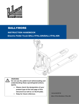 Ballymore BALLYPAL 45N-27 Owner's manual
-
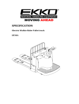 EKKO EP30A User manual
-
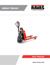 Ravas Ergo Truck User manual
-
Manitou MT 932 User manual
-
Doosan B20S-5 Operation & Maintenance Manual
-
Jungheinrich ETM 214 Operating instructions
-
AUSA C300H x4 User manual
-
 AUSA C 400 H User manual
-
Princeton Truck Mounted Forklift User manual
-
Daewoo G33P-3 Operation & Maintenance Manual


