Page is loading ...

HYPER INVERTER PACKAGED AIR-CONDITIONERS
(Split system, Air to air heat pump type)
Twin type
FDTC71VNXPVD
FDTC100VNXPVD
FDTC100VSXPVD
FDTC125VNXPVD
FDTC125VSXPVD
Triple type
FDTC140VNXTVD
FDTC140VSXTVD
CEILING CASSETTE- 4 WAY COMPACT TYPE
Single type
FDUM71VNXVD
FDUM100VNXVD
FDUM100VSXVD
FDUM125VNXVD
FDUM125VSXVD
FDUM140VNXVD
FDUM140VSXVD
Twin type
FDUM100VNXPVD
FDUM100VSXPVD
FDUM125VNXPVD
FDUM125VSXPVD
FDUM140VNXPVD
FDUM140VSXPVD
Triple type
FDUM140VNXTVD
FDUM140VSXTVD
DUCT CONNECTED-LOW/MIDDLE STATIC PRESSURE TYPE
Single type
FDU71VNXVD
FDU100VNXVD
FDU100VSXVD
FDU125VNXVD
FDU125VSXVD
FDU140VNXVD
FDU140VSXVD
DUCT CONNECTED-HIGH STATIC PRESSURE TYPE
Single type
FDT71VNXVD
FDT100VNXVD
FDT100VSXVD
FDT125VNXVD
FDT125VSXVD
FDT140VNXVD
FDT140VSXVD
Twin type
SRK100VNXPZIX
SRK100VSXPZIX
SRK125VNXPZIX
SRK125VSXPZIX
Triple type
SRK140VNXTZIX
SRK140VSXTZIX
WALL MOUNTED TYPE
Twin type
FDT71VNXPVD
FDT100VNXPVD
FDT100VSXPVD
FDT125VNXPVD
FDT125VSXPVD
FDT140VNXPVD
FDT140VSXPVD
Triple type
FDT140VNXTVD
140VSXTVD
CEILING CASSETTE- 4 WAY TYPE
Single type
FDEN71VNXVD
FDEN100VNXVD
FDEN100VSXVD
FDEN125VNXVD
FDEN125VSXVD
FDEN140VNXVD
FDEN140VSXVD
Twin type
FDEN71VNXPVD
FDEN100VNXPVD
FDEN100VSXPVD
FDEN125VNXPVD
FDEN125VSXPVD
FDEN140VNXPVD
FDEN140VSXPVD
Triple type
FDEN140VNXTVD
140VSXTVD
CEILING SUSPENDED TYPE
Manual No. '10 •PAC - DB - 13A
DATA BOOK
DRAFT
Ceiling Cassette - 4 way type
>FDT71VNXVD
>FDT125VNXVD
>FDT140VNXVD
Ceiling Suspended type
>FDEN71VNXVD
>FDEN125VNXVD
>FDEN140VNXVD
Ducted - Medium to High Static type
>FDU71VNXVD
>FDU125VNXVD
>FDU140VNXVD
Service Manual

-
2
-
'10 • PAC-SM-137A
1.
OUTLINE OF OPERATION CONTROL BY MICROCOMPUTER
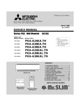
1.1 Remote controller
(1) Wired remote controller
The figure below shows the remote controller with the cover opened. Note that all the items that may be displayed in the liquid
crystal display area are shown in the figure for the sake of explanation
Characters displayed with dots in the liquid crystal display area are abbreviated.
䋪㩷All displays are described in the liguid crystal display for explanation.
The figure below shows the remote control with the cover opened.
Ventilaion display
Displayed during ventilation operation
Centeal control display
Displayed when the air conditioning system is
controlled by centralized remote control.
Timer operation display
Displays the timer operation setting.
Temperature setting buttons
These buttons are used to set the
temperature of the room.
Timer button
This button is used to set
the timer mode.
Timer setting buttons
These buttons are used to set
the timer mode and the time.
GRILL button
This button has no function.
When this button is pressed,
(Invalid Operation)
is displayed, but it does not mean a failure.
Cover
AIR CON No. button
Display the indoor unit number connected to this
remote controller.
CHECK button
This button is used at servicing.
TEST button
This button is used during test operation.
Weekly timer display
Displays the settings of the
weekly timer.
Operation setting display area
Displays setting temperature, airflow
volume, operation mode and oparation
message.
Operation/check indicator light
During oparation: Lit in green
In case of error: Flashing in red
Operation/stop button
This button is used to operate and stop
the air conditioning system.
Press the button once to operate the
system and press it once again to stop
the system.
MODE button
This button is used to change the
operation mode.
FAN SPEED button
This button is used to set the airflow
volume.
VENT button
This button is used to operate external
ventilator.
LOUVER button
This button is used to operate/stop the
swing louver.
SET button
٨This button is used to fix the setting.
٨This button is used to set the silent mode.
RESET button
٨Press this button while making settings to go back to the
previous operation.
٨This button is also used to reset the "FILTER CLEANING" display.
(Press it after cleaning the air filter)

-
3
-
'10 • PAC-SM-137A
(2) Wireless remote controller
FDEN series only
* All displays are described in the liquid crystal display for explanation
Indication section
Operation section
Indicates set temperature. Indicates the status of swing louver.
Indicates selected operation with .
Indicates for two seconds when FILTER
button is pressed.
Indicates when OFF-TIMER is set.
Indicates OFF-TIMER setting time. Indicates the
current time when the OFF-TIMER is not set.
When this is pressed once, the unit starts to
operate and when this is pressed once again,
it stops operating.
Used to swing the louver.
Every time this button is pressed, displays switch
as below.
Sets room temperature by pressing or button.
Sets time when setting the time.
Used to cancel the TIMER SETTINGS.
Used to reset the microcomputer.
Indicates the selected airflow volume
Indicates when ON-TIMER is set.
Indicates the ON-TIMER setting time.
Nothing displayed when ON-TIMER is
not set.
Sends signal to the air conditioner.
Every time this button is pressed, the mode is
switched as below.
Used to reset (turn off) the filter sign.
Press the button only after completing
the filter cleaning.
Sets ON TIMER operation.
Sets OFF TIMER operation.
Sets current time.

-
4
-
'10 • PAC-SM-137A
1.2 Operation control function by the wired remote controller
(1) Switching sequence of the operation mode switches of remote controller
$29 #//, &!. (%!4 !54/
(2) [CPU reset]
This functions when “CHECK” and “GRILL” buttons on the remote controller are pressed simultaneously. Operation is same
as that of the power supply reset.
(3) [Power failure compensation function]...Electric power supply failure
• This becomes effective if “Power failure compensation effective” is selected with the setting of remote controller function.
• Since it memorizes always the condition of remote controller, it starts operation according to the contents of memory no
sooner than normal state is recovered after the power failure. Although the auto swing stop position and the timer mode are
cancelled, the weekly timer setting is restored with the holiday setting for all weekdays.
After recovering from the power failure, it readjusts the clock and resets the holiday setting for each weekday so that the
setting of weekly timer becomes effective.
• Content memorized with the power failure compensation are as follows.
Note (1) Items, and are memorized regardless whether the power failure compensation is effective or not while the setting of silent mode is cancelled
regardless whether the power failure compensation is effective or not.
At power failure – Operating/stopped
If it had been operating under the off timer mode, sleep timer mode, the state of stop is memorized. (Although the
timer mode is cancelled at the recovery from power failure, the setting of weekly timer is changed to the holiday
setting for all weekdays.)
Operation mode
Airflow volume mode
Room temperature setting
Louver auto swing/stop
However, the stop position (4-position) is cancelled so that it returns to Position (1).
“Remote controller function items” which have been set with the remote controller function setting (“Indoor
function items” are saved in the memory of indoor unit.)
Upper limit value and lower limit value which have been set with the temperature setting control
Sleep timer and weekly timer settings (Other timer settings are not memorized.)
[Parts layout on remote controller PCB]
Master/ slave setting when more than one remote controllers are used
A maximum of two remote controllers can be connected to one indoor unit (or one group of indoor units.)
Caution
When using multiple remote controllers, the following dispiays or settings
cannot be done with the slave remote controller. It is available only with
the master remote controller.
ޓLouver position setting (set upper or lower limit of swinging range)
ޓSetting indoor unit functions
ޓSetting temperature range
ޓOperation data display
ޓError data display
ޓSilent mode setting
ޓTest operation of drain pump
ޓRemote controller sensor setting
Remote controller cord (no polarity)
Remote controller
SW1 "Master"
Switch Setting Contents
M Master remote controller
SW1 S Slave remote controller
Remote controller
SW1 "Slave"
Lower
Master
Slave
Upper
Board
Indoor units
Set SW1 to "Slave" for the slave remote controller. It was factory set to "Master" for shipment.
Note: The setting "Remote controller thermistor enabled" is only selectable with the master remote
controller in the position where you want to check room temperature.
The air conditioner operation follows the last operation of the remote controller regardless of the
master/ slave setting of it.

-
5
-
'10 • PAC-SM-137A
1.3 Operation control function by the indoor controller
(1) FDT, FDEN, FDU series
(a) Auto operation
If “Auto” mode is selected by the remote controller, the heating and the cooling are automatically switched according to the
difference between outdoor air temperature and setting temperature and the difference between setting temperature and return
air temperature. (When the switching of cooling mode ¢ heating mode takes place within 3 minutes, the compressor does
not operate for 3 minutes by the control of 3-minute timer.) This will facilitate the cooling/heating switching operation in
intermediate seasons and the adaptation to unmanned operation at stores, etc (ATM corner of bank).
Note (1) Room temperature control during auto cooling/auto heating is performed according to the room temperature setting temperature. (DIFF: ±1 deg)
(2) If the indoor heat exchanger temperature rises to 59°C or higher during
heating operation, it is switched automatically to cooling operation. In
addition, for 1 hour after this switching, the heating operation is not
performed, regardless of the temperature shown at right.
Room temperature setting temperature
+3-3
Cooling operation
Heating operation
Room temperature (detected with ThI-A) [deg]
5956
Heating operation stopped (cooling)
Heating OK
Indoor heat exchanger temperature (°C)
(b) Operations of functional items during cooling/heating
Cooling Heating
Dehumidify
Fan
Operation
Functional item
Thermostat
ON
Thermostat
ON
Thermostat
OFF
Thermostat
OFF
Hot start
(Defrost)
Compressor
4-way valve
Outdoor unit fan
Indoor unit fan
Louver motor
Drain pump (3)
(2)
(2)
/
/
/
/×
()
()
/
/
/
/
/
/
Thermostat ON:
Thermostat OFF:
(2)
/
/(2)
Note (1) : Operation : Stop /: Turned ON/OFF by the control other than the room temperature control.
(2) ON during the drain motor delay control.
(3) Drain pump ON setting may be selected with the indoor unit function setting of the wired remote controller.
(c) Dehumidifying operation
Return air temperature thermistor [ThI-A (by the remote controller when the remote controller thermistor is enabled)] controls
the indoor temperature environment simultaneously.
1) Operation is started in the cooling mode. When the difference between the return air temperature and the setting
temperature is 2°C or less, the indoor unit fan tap is brought down by one tap. That tap is retained for 3 minutes after
changing the indoor unit fan tap.
2) If the return air temperature exceeds the setting temperature by 3°C during defrosting operation, the indoor unit fan tap is
raised. That tap is retained for 3 minutes after changing the indoor unit fan tap.
3) If the thermostat OFF is established during the above control, the indoor unit fan tap at the thermostat ON is retained so
far as the thermostat is turned OFF.
4) After stopping the cooling operation, the indoor unit continues to run at Lo for 15 seconds.

-
6
-
'10 • PAC-SM-137A
(d) Timer operation
1) Sleep timer
Set the duration of time from the present to the time to turn off the air-conditioner.
It can be selected from 10 steps in the range from “OFF 1 hour later” to “OFF 10 hours later”. After the sleep timer
setting, the remaining time is displayed with progress of time in the unit of hour.
2) OFF timer
Time to turn OFF the air-conditioner can be set in the unit of 10 minutes.
3) ON timer
Time to turn ON the air-conditioner can be set. Indoor temperature can be set simultaneously.
4) Weekly timer
Timer operation (ON timer, OFF timer) can be set up to 4 times a day for each weekday.
5) Timer operations which can be set in combination
Sleep timer
OFF timer
ON timer
Weekly timer
Sleep timer
OFF timer
ON timer
Weekly timer
Note (1) : Allowed : Not
Item
Item
(e) Remote controller display during the operation stop
1) “Centralized control ON” is displayed always on the LCD under the “Center/Remote” and “Center” modes during the
operation stop (Power ON). This is not displayed under the “Remote” mode.
2) If this display is not shown under the “Center/Remote” mode, check if the indoor unit power switch is turned on or not.
(f) Hot start (Cold draft prevention at heating)
At the startup of heating operation, at resetting of the thermostat, during defrost operation and at returning to heating, the
indoor fan is controlled by the indoor heat exchanger temperature (detected with ThI-R) for preventing the cold draft.
Judgment by heating start thermostat
Normal condition/Set airflow volume
Thermostat OFF Thermostat ON
Compressor OFF Compressor ON End of defrosting
Heat exchanger temp. 35
˚C
or higher, or after 7 minutes Heat exchanger temp. 35
˚C
or higher, or after 7 minutes
Defrosting start
Fan
Lo
Lo
Set airflow volume
Set airflow volume
Indoor heat exchanger temperature (˚C)
Indoor heat exchanger temperature (˚C)
35
35 45
25 35
Indoor heat exchanger temperature (˚C)
Set airflow volume
Fan
OFF
Lo
25 35 45
Set airflow volume
Fan
OFF
Indoor heat exchanger temperature (˚C)
Fan
Lo
1
Note (1) Heating preparation is displayed during the hot start (when the compressor is operating and the indoor fan does not provide the set airflow volume).

-
7
-
'10 • PAC-SM-137A
(g) Hot keep
Hot keep control is performed at the start of the defrost control.
1) Control
a) When the indoor heat exchanger temperature (detected with ThI-R1 or R2) drops to 35°C or lower, the speed of
indoor fan is changed to the lower tap at each setting.
b) During the hot keep, the louver horizontal control signal is transmitted.
2) Ending condition
When the indoor fan is at the lower tap at each setting, it returns to the set airflow volume as the indoor heat exchanger
temperature rises to 45°C or higher.
(h)
Fan control during the heating thermostat OFF
When the heating thermostat is turned OFF, the setting of the fan control is selectable using the indoor function of wired remote
controller [ FAN CONTROL].
1) Low fan speed (Factory default)
If the indoor heat exchanger temperature drops below 35°C with the heating thermostat OFF, the indoor fan operate at the
lower speed tap at each setting.
2) Set fan speed
Even if the indoor heat exchanger temperature drops below 35°C with the heating thermostat OFF, the indoor fan
continues to run at the set airflow volume.
3) Intermittence
If the indoor heat exchanger temperature drops below 35°C with the heating thermostat OFF, the indoor fan operates at
the lower speed tap at each setting and, when the indoor heater exchanger temperature drops below 25°C, the indoor fan
stops for 5 minutes. Then the fan runs at the low speed tap for 2 minutes, and the judgment is made by the thermostat.
4) Fan OFF
If the indoor heat exchanger temperature drops below 35°C with the heating thermostat OFF, the indoor fan is turned
OFF. The same applies also when the remote controller sensor is effective.
(i) Filter sign
As the operation time (Total ON time of ON/OFF switch) accumulates to 180 hours (1), “FILTER CLEANING” is displayed
on the remote controller. (This is displayed when the unit is in trouble and under the centralized control, regardless of ON/OFF)
Note (1) Time setting for the filter sign can be made as shown below using the indoor function of wired remote controller “FILTER SIGN SET”. (It is set at 1 at the
shipping from factory.)
Filter sign setting
TYPE 1
TYPE 2
TYPE 3
TYPE 4
Function
Setting time: 180 hrs (Factory default)
Setting time: 600 hrs
Setting time: 1,000 hrs
Setting time: 1,000 hrs (Unit stop)
(2)
(2) After the setting time has elapsed, the “FILTER CLEANING” is displayed and, after operating for 24 hours further (counted also during the stop), the
unit stops.
(j) Auto swing control [Applicable model: FDT and FDEN]
1) Louver control
a) Press the “LOUVER” button to operate the swing louver when the air conditioner is operating.
“SWING
” is displayed for 3 seconds and then the swing louver moves up and down continuously.
b) To fix the swing louver at a position, press one time the “LOUVER” button while the swing louver is moving so that
four stop positions are displayed one after another per second.
When a desired stop position is displayed, press the “LOUVER” button again. The display stops, changes to show
the “STOP 1 ” for 5 seconds and then the swing louver stops.
c) Louver operation at the power on with a unit having the louver 4-position control function
The louver swings one time automatically (without operating the remote controller) at the power on.
This allows inputting the louver motor (LM) position, which is necessary for the microcomputer to recognize the
louver position.
Note (1) If you press the “LOUVER” button, the swing motion is displayed on the louver position LCD for 10 second. The display changes to the
“SWING ” display 3 seconds later.

-
8
-
'10 • PAC-SM-137A
2) Automatic louver level setting during heating
At the hot start with the heating thermostat OFF, regardless whether the auto swing switch is operated or not (auto swing
or louver stop), the louver takes the level position (In order to prevent the cold start). The louver position display LCD
continues to show the display which has been shown before entering this control.
3) Louver-free stop control
When the louver-free stop has been selected with the indoor function of wired remote controller “ POSITION”, the
louver motor stops when it receives the stop signal from the remote controller. If the auto swing signal is received from
the remote controller, the auto swing will start from the position where it was before the stop.
Note (1) When the indoor function of wired remote controller “ POSITION” has been switched, switch also the remote control function “
POSITION” in the same way.
(k) Compressor inching prevention control
1) 3-minute timer
When the compressor has been stopped by the thermostat, remote controller operation switch or anomalous condition,
its restart will be inhibited for 3 minutes. However, the 3-minute timer is invalidated at the power on the electric power
source for the unit.
2) 3-minute forced operation timer
• Compressor will not stop for 3 minutes after the compressor ON. However, it stops immediately when the unit is
stopped by means of the ON/OFF switch or by when the thermister turned OFF the change of operation mode.
• If the thermostat is turned OFF during the forced operation control of heating compressor, the louver position (with the
auto swing) is returned to the level position.
Note (1) The compressor stops when it has entered the protective control.
(l) Drain motor (DM) control [Applicable model: FDT, FDU]
1) Drain motor (DM) is operated during the cooling or dehumidifying mode operations and simultaneously with the
compressor ON. The DM continues to operate for 5 minutes after the operation stop, anomalous stop, thermostat stop or
when it was switched from the cooling and dehumidifying operations to the fan or heating operation.
Stop (1)
Indoor unit operation mode
Control A
Control B
Compressor ON
Compressor OFF
Cooling
Dehumidifying
HeatingFan (2) Note (1) Including the stop from the cooling, dehumidifying, fan
and heating, and the anomalous stop
(2) Including the “Fan” operation according to the
mismatch of operation modes
a) Control A
i) If the float switch detects any anomalous draining condition, the unit stops with the anomalous stop (displays
E9) and the drain pump starts. After detecting the anomalous condition, the drain motor continues to be ON.
ii) It keeps operating while the float switch is detecting the anomalous condition.
b) Control B
If the float switch detects any anomalous drain condition, the drain motor is turned ON for 5 minutes, and at 10
seconds after the drain motor OFF it checks the float switch. If it is normal, the unit is stopped under the normal
mode or, if there is any anomalous condition, E9 is displayed and the drain motor is turned ON. (The ON condition
is maintained during the drain detection.)
2) Drain motor (DM) interlock control
a) Start conditions
Depending on the function setting by the remote controller, the drain motor is turned ON under either one of the
following conditions.
i) During heating mode operation (Both the thermostat ON/OFF)
ii) During heating mode operation (Both the thermostat ON/OFF) + Fan operation
iii) Fan operation
b) End conditions
The drain motor is turned OFF 5 minutes after the stop of operations i) to iii) above.
(m) Operation check/drain pump test run operation mode
1)
If the power is turned on by the dip switch (SW7-1) on the indoor PCB when electric power source is supplied, it enters the
mode of operation check/drain pump test run. It is ineffective (prohibited) to change the switch after turning power on.
2) When the communication with the remote controller has been established within 60 seconds after turning power on by the
dip switch (SW7-1) ON, it enters the operation check mode. Unless the remote controller communication is established, it
enters the drain pump test run mode.
Note (1) To select the drain pump test run mode, disconnect the remote controller connector (CNB) on the indoor PCB to shut down the remote controller
communication.

-
9
-
'10 • PAC-SM-137A
3) Operation check mode
There is no communication with the outdoor unit but it allows performing operation in respective modes by operating the
remote controller.
4) Drain pump test run mode
As the drain pump test run is established, the drain pump only operates and during the operation protective functions by
the microcomputer of indoor unit become ineffective.
(n) Cooling, dehumidifying frost protection
1) To prevent frosting during cooling mode or dehumidifying mode operation, the of compressor speed is reduced if
the indoor heat exchanger temperature (detected with ThI-R) drops to 1.0 °C or lower at 4 minutes after the start of
compressor operation. If the indoor unit heat exchanger temperature is 1.0 °C or lower after 1 minutes, the compressor
speed is reduced further. If it becomes 2.5 °C or higher, the control terminates. When the indoor heat exchanger
temperature has become as show below after reducing the compressor speed, it is switched to the fan operation. For the
selection of indoor fan speed, refer to item 2).
101.0
Indoor heat exchanger temperature (°C)
Fan operation
Cooling operation
2) Selection of indoor fan speed
If it enters the frost prevention control during cooling operation (excluding dehumidifying), the indoor unit fan speed is
switched.
(a) In cases of FDU and FDEN
i) When the indoor unit return air temperature (detected with ThI-A) is 23°C or lower, this control is invalidated
and, as 2 hours elapse after starting the frost prevention control, it is terminated.
ii) If it is detected again within 15 minutes from the start of frost prevention control, the indoor fan speed is raised
by 1 tap to increase the indoor unit fan speed. If it is detected within further 15 minutes, the indoor unit fan
speed is raised by 1 tap more.
Note (1) Indoor unit fan speed can be increased by up to 2 taps.
iii) “ FAN SPEED SW VALID/INVALID” of this control is selectable with the function setting of remote
controller.
b) In the case of FDT
i) When the indoor return air detection temperature (detected with ThI-A) is 23°C or higher and the indoor heat
exchanger temperature (detected with ThI-R) detects the compressor frequency drop start temperature A°C+1°C,
of indoor unit fan speed is increased by 20rpm.
ii) If the phenomenon of i) above is detected again after the acceleration of indoor unit fan, indoor unit fan speed
is increased further by 20rpm.
Note (1) Indoor unit fan speed can be increased by up to 2 taps.
• Compressor frequency drop start temperature
Symbol
Item A
Temperature - Low (Factory default) 1.0
Temperature - High 2.5
Note (1) Frost prevention temperature setting can be selected with the indoor unit function setting of the wired remote controller.
(o) Heating overload protection
1) If the indoor heat exchanger temperature (detected with ThI-R) at 63°C or higher is detected for 2 seconds continuously,
the compressor stops. When the compressor is restarted after a 3-minute delay, if a temperature at 63°C or higher is
detected for 2 seconds continuously within 60 minutes after initial detection and if this is detected 5 times consecutively,
the compressor stops with the anomalous stop (E8). Anomalous stop occurs also when the indoor heat exchanger
temperature at 63°C or higher is detected for 6 minutes continuously.
56 63
Indoor heat exchanger temperature (°C)
Compressor ON
Compressor OFF
2) Indoor unit fan speed selection
If, after second detection of heating overload protection up to fourth, the indoor fan is set at Me and Lo taps when the
compressor is turned ON, the indoor fan speed is increased by 1 tap.

-
10
-
'10 • PAC-SM-137A
(p) Anomalous fan motor [In case of FDT only]
After starting the fan motor, if the fan motor speed is 200rpm or less is detected for 30 seconds continuously and 4 times within
60 minutes, then fan motor stops with the anomalous stop (E16).
(q) Plural unit control – Control of 16 units group by one remote controller
1) Function
One remote controller switch can control a group of multiple number of unit (Max. 16 indoor units). “Operation mode”
which is set by the remote controller switch can operate or stop all units in the group one after another in the order of unit
No.(1). Thermostat and protective function of each unit function independently.
Note (1) Unit No. is set by SW2 on the indoor unit control PCB. Unit No. setting by SW2 is necessary for the indoor unit only. In cases of the twin, triple
and double-twin specification, it is necessary set for the master and the slave units. This can be selected by SW5. (All are set for the master unit at
the shipping from factory.)
SW2: For setting of 0 – 9, A – F
SW5: For setting of master and slave units
(See table shown at right.)
Remote controller
Indoor unit
Outdoor unit
Signal wiring
between outdoor unit
and indoor units
(Master unit) (Slave unit a) (Slave unit b)
Remote controller wiring
R
0123 F
444
(Slave unit c)
4
Refrigerant piping
Master unit OFF OFF
OFF ON
SW5-1 SW5-2
ON OFF
ON ON
Slave unit a
Slave unit b
Slave unit c
Switch
Unit
SW5 setting
(2) Unit No. may be set at random unless duplicated, it should be better to set orderly like 0, 1, 2…, F to avoid mistake.
2) Display to the remote controller
a) Center or each remote controller basis, heating preparation: the youngest unit No. among the operating units in the
remote mode (or the center mode unless the remote mode is available) is displayed.
b) Inspection display, filter sign: Any of unit that starts initially is displayed.
c) Confirmation of connected units
Pressing “AIR CON No.” button on the remote controller displays the indoor unit address. If “S” “T” button is
pressed at the next, it is displayed orderly starting from the unit of youngest No.
d) In case of anomaly
i) If any anomaly occurs on a unit in a group (a protective function operates), that unit stops with the anomalous
stop but any other normal units continue to run as they are.
ii) Signal wiring procedure
Signal wiring between indoor and outdoor units should be made on each unit same as the normal wiring.
For the group control, lay connect with sires wiring between rooms using terminal blocks (X, Y) of remote
controller.
Connect the remote controller communication wire separately from the power supply wire or wires of other
electric devices (AC220V or higher).
(r) High ceiling control
In the case of indoor unit installed in a higher ceiling room, the airflow volume mode control can be changed with the wired
remote controller indoor unit function “FAN SPEED SET”.
-------
UH-HiUH-MeUH-Hi-Me
STANDARD
HIGH SPEED1, 2
FAN SPEED SET Hi-Lo Hi-MeHi-Me-Lo
UH-UH-Hi-Me
UH-Hi-Me-Lo
Indoor unit airflow setting
Fan tap
Note (1) Factory default is Standard.
(2) At the hot-start and heating thermostat OFF, or other, the indoor unit fan is operated at the low speed tap of each setting.

-
11
-
'10 • PAC-SM-137A
(s)
Abnormal temperature thermistor (return air/indoor heat exchanger) wire/short-circuit detection
1) Broken wire detection
When the return air temperature thermistor detects -50°C or lower or the heat exchanger temperature thermistor detect
-50°C or lower for 5 seconds continuously, the compressor stops. After a 3-minute delay, the compressor restarts but,
if it is detected again within 60 minutes after the initial detection for 6 minutes continuously, stops again (the return air
temperature thermistor: E7, the heat exchanger temperature thermistor: E6).
2) Short-circuit detection
If the heat exchanger temperature thermistor detects 70°C or higher for 5 seconds continuously at 2 minutes and 20
seconds after the compressor ON during cooling operation, the compressor stops (E6).
(t) Operation permission/prohibition
(In case of adopting card key switches or commercially available timers)
When the indoor function setting of wired remote controller for “Operation permission/prohibition” is changed from “Invalid
(Factory default)” to “ Valid”, following control becomes effective.
XR5
Card key
switch
XR1
1
2
3
4
5
6
XR3
XR4
CnT
Blue
12V
XR2
Optional
XR5
Normal operation
(Factory default)
Operation permission/prohibition mode
“Valid” (Local setting)
CnT-6
ON OFF ON OFF
Operation Stop Operation
permission*1
Operation prohibition
(Unit stops)
*1
Only the “LEVEL INPUT” is acceptable for external input, however when the indoor function setting of
“Level input (Factory default)” or “Pulse input” is selected by the function for “External input” of the wired remote
controller, operation status will be changed as follows.
In case of “Level input” setting In case of “Pulse input” setting
Unit operation from the wired
remote controller becomes
available*(1)
Unit starts operation
*(2)
*(1) In case that “Operation permission/prohibition mode” setting is “Valid” and “External input” setting is “Level
input (Factory default)”;
When card key switch is ON (CnT-6 ON: Operation permission), start/stop operation of the unit from the
wired remote controller becomes available.
When card key switch is OFF (CnT-6 OFF: Operation prohibition), the unit stops operation in conjunction
with OFF signal, and start/stop operation of the unit from the wired remote controller becomes not available.
*(2) In case that “Operation permission/prohibition mode” setting is “Valid” and “External input” setting is “Pulse
input (Local setting)”;
When card key switch is ON (Operation permission), the unit starts operation in conjunction with ON signal.
and also start/stop operation of the unit from the wired remote controller becomes available.
When card key switch is OFF (Operation prohibition), the unit stops operation in conjunction with OFF signal, and
start/stop operation of the unit from the wired remote controller becomes not available.
(3) This function is invalid only at “Center mode” setting done by central controller.

-
12
-
'10 • PAC-SM-137A
(u) External input/output control (CnT)
Be sure to connect the wired remote controller to the indoor unit. Without wired remote controller remote operation by CnT is
not possible to perform.
Operation output (CnT-2: XR1)
Heating output (CnT-3: XR2)
Thermostat ON output (CnT-4: XR3)
Error output (CnT-5: XR4)
Remote operation input (CnT-6: No-voltage contactor)
XR1
1
2
3
4
5
6
XR3
XR4
CnT
Blue
12V
XR2
Optional
XR5
1) Output for external control (remote display)
Following output connectors (CnT) are provided on the indoor control PCB for monitoring operation status.
Operation output: Outputs DC12V signal for driving relay during operation
Heating output: Outputs DC12V signal for driving relay during heating operation
Thermostat ON output: Outputs DC12V signal for driving relay when compressor is operating.
Error output: Outputs DC12V signal for driving relay when anomalous condition occurs.
2) Remote operation input
Remote operation input connector (CnT-6) is provided on the indoor control PCB.
However remote operation by CnT-6 is not effective, when “Center mode” is selected by center controller.
In case of plural unit (twin, triple, double twin), remote operation input to CnT-6 on the slave indoor unit is invalid.
Only the “LEVEL INPUT” is acceptable for external input, however when the indoor function setting of “Level
input (Factory default)” or “Pulse input” is selected by the function for “External input” of the wired remote controller,
operation status will be changed as follows.
a) In case of “Level input” setting (Factory default)
Input signal to CnT-6 is OFF→ON …… unit ON
Input signal to CnT-6 is ON→OFF …… unit OFF
Operation is not inverted.
ONON
OFF OFF
OFF OFF
OFF OFF
ON
ON
ON
ON
OFF
OFF
CnT-6 input
Unit A
Unit B
Note: The latest operation has priority
It is available to operate/stop by remote controller or center controller
b) In case of “Pulse input” setting (Local setting)
It is effective only when the input signal to CnT-6 is changed OFF→ON, and at that time unit operation [ON/OFF] is
inverted.
ON
ON
OFF OFF
OFF
OFF
ON
ON
ON
OFF
OFF
CnT-6 input
Unit A
Unit B

-
13
-
'10 • PAC-SM-137A
3) Remote operation
a) In case of multiple units (Max. 16 indoor units group) are connected to one wired remote
controller
When the indoor function setting of wired remote controller for “External control set” is changed from “Individual
(Factory default)” to “ For all units”, all units connected in one wired remote controller system can be controlled by
external operation input.
Ex. Indoor units =
XY Wired remote controller
Refrigerant piping
Indoor unit
Signal &
Power
XY
123
123
XY
123
123
XY
123
123
XY
123
123
XY
123
123
XY
123
XY
123
XY
123
Indoor unit
Outdoor unit Outdoor unit Outdoor unit Outdoor unit Outdoor unit
Indoor unit Indoor unit
䇭(master)
Indoor unit
Indoor unit
䇭(slave)
Indoor unit
䇭(slave)
Indoor unit
䇭(slave)
Cn
External
input
Individual operation (Factory default) All units operation (Local setting)
CnT-6
ON OFF ON OFF
Only the unit
directly connected
to the remote
controller can be
operated.
Only the unit
directly connected
to the remote
controller can be
stopped opeartion.
All units in one
remote controller
system can be
operated.
All units in one
remote controller
system can be
stopped operation.
Unit only Unit only Units Units
When more than one indoor unit (Max. 16 indoor units) are connected in one wired remote controller system:
(1) With the factory default, external input to CnT-6 is effective for only the unit .
(2) When setting “For all unit” (Local setting), all units in one remote controller system can be controlled by external
input to CnT-6 on the indoor unit .
(3) External input to CnT-6 on the other indoor unit than the unit is not effective.
(v) Fan control at heating startup (Applicable model: FDT)
1) Start
conditions
At the start of heating operation, if the difference of setting temperature and return air temperature is 5°C or higher after
the end of hot start control, this control is performed.
2) Contents of control
a) Sampling is made at each minute and, when the indoor unit heat exchanger temperature (detected with ThI-R) is
37°C or higher, present number of revolutions of indoor unit fan speed is increased by 10min-1.
b) If the indoor unit heat exchanger temperature drops below 37°C at next sampling, present number of revolutions of
indoor unit fan speed is reduced by 10min-1.
3) End conditions
Indoor fan speed is reduced to the setting airflow volume when the compressor OFF is established and at 30 minutes after
the start of heating operation.

-
14
-
'10 • PAC-SM-137A
(w) Room temperature detection temperature compensation during heating
With the standard specification, the compressor is turned ON/OFF with the thermostat setting temperature. When the thermostat
is likely to turn OFF earlier because the unit is installed at the ceiling where warm air tends to accumulate, the setting can be
changed with the wired remote controller indoor unit function “ ”. The compressor and the heater are turned ON/OFF
at one of the setting temperature +3, +2 or +1°C in order to improve the feeling of heating. The setting temperature, however,
has the upper limit of 30°C.
Compressor Compressor
Standard Operation
Stop
Setting temperature
-1 +1
Room temperature (deg)
Operation
Stop
Setting temperature
+2 +4
Room temperature (deg)
When it is set at +3°C
(x) Return air temperature compensation
This is the function to compensate the deviation between the detection temperature by the return air temperature thermistor and
the measured temperature after installing the unit.
1) It is adjustable in the unit of 0.5°C with the wired remote controller indoor unit function “RETURN AIR TEMP”.
• +1.0°C, +1.5°C, +2.0°C • -1.0°C, -1.5°C, -2.0°C
2) Compensated temperature is transmitted to the remote controller and the compressor to control them.
Note (1) The detection temperature compensation is effective on the indoor unit thermistor only.

-
15
-
'10 • PAC-SM-137A
1.4 Operation control function by the outdoor controller
(1) Determination of compressor speed (frequency)
Required frequency
(a) Cooling/dehumidifying operation Unit: rps
Model
71 100 125 140
Max. required
frequency
Indoor unit air flow “P-Hi”, “Hi” 88 75 95 95
Indoor unit air flow “Me”, “Lo” 80 60 60 70
Min. required frequency 20 20 20 20
(b) Heating operation Unit: rps
Model
71 100 125 140
Max. required
frequency
Indoor unit air flow “P-Hi”, “Hi” 112 120 120 120
Indoor unit air flow “Me”, “Lo” 90 60 70 70
Min. required frequency 20 20 20 20
(c) If “Silent mode start” signal is received from the remote controller, the maximum required frequency becomes same as
when the indoor air flow is set at “Lo”.
(d) Max. required frequency under high outdoor air temperature in cooling mode
Maximum required frequency is selected according to the outdoor air temperature (Tho-A).
Unit: rps
Model
71 100 125 140
Max. required
frequency
Outdoor air temperature is
40°C or higher 76 75 75 75
Outdoor air temperature is
46°C or higher 62 75 70 70
(e) Max. required frequency under outdoor air temperature in heating mode
Maximum required frequency is selected according to the outdoor air temperature (Tho-A).
Unit: rps
Model
71 100 125 140
Max. required
frequency
Outdoor air temperature is
18°C or higher 76 60 80 85
(f) Selection of max. required frequency by heat exchanger temperature
1) Maximum required frequency is selected according to the outdoor unit heat exchanger temperature (Tho-R) during
cooling/dehumidifying or according to the indoor unit heat exchanger temperature (ThI-R) during heating mode.
2) When there are 3 indoor unit heat exchanger temperatures (ThI-R), whichever the highest applies,
Unit: rps
Model
71 100 125 140
Max. required
frequency
Cooling/
dehumidifying
Outdoor unit heat exchanger
temperature is 56°C or higher
––––
Heating
Indoor unit heat exchanger
temperature is 56°C or higher
– 100 100 100
(g) When any of the controls from (a) to (f) above may duplicate, whichever the smallest value among duplicated controls is
taken as the maximum required frequency.
(h) During heating, it is operated with the maximum required frequency until the indoor unit heat exchanger temperature
becomes 40°C or higher.
(2) Compressor start control
(a) Compressor starts upon receipt of the thermostat ON signal from the indoor unit.
(b) However, at initial start after turning the power supply breaker, it may enter the standby state for maximum 30 minutes
(“ PREPARATION” is displayed on the remote controller) in order to prevent the oil loss in the compressor.
If the cooling/dehumidifying/heating operation is selected from the remote controller when the outdoor unit is in the
standby state, “ PREPARATION” is displayed for 3 seconds on the remote controller.

-
21
-
'10 • PAC-SM-137A
(3) Compressor soft start control
(a) Compressor protection start I
[Control condition] Normally, the compressor operation frequency is raised in this start pattern.
[Control contents] 1) Starts with the compressor’s target frequency at A rps.
However, when the ambient air temperature (Tho-A) is 35°C or higher during cooling/
dehumidifying or the indoor return air temperature (ThI-A) is 25°C or higher during heating, it
starts at C rps.
2) At 30 seconds after the start of compressor, its target frequency changes to B rps and the
compressor is operated for 2 - 4 minutes with its operation frequency fixed at B rps.
Model
Operation mode
A rps B rps C rps
71 Cooling/Dehumidifying 42 42 40
Heating 62 62 40
100 Cooling/Dehumidifying 55 55 30
Heating 55 55 30
125, 140 Cooling/Dehumidifying 45 45 25
Heating 45 45 25
(b) Compressor protection start III
[Control condition] Number of compressor starts is only 1 counted after the power supply breaker ON.
[Control contents] Operates by selecting one of following start patterns according to the operation mode and the
outdoor air temperature (Tho-A).
1) Low frequency operation control during cooling/dehumidifying
[Control condition] Upon establishing the conditions of compressor protection start III, the low frequency
operation control is performed during cooling/dehumidifying.
[Control contents] a) Starts with the compressor’s target frequency at A rps. When the outdoor air temperature
(Tho-A) is 35°C or higher, it starts at C rps.
b) At 30 seconds after the compressor start, the compressor’s target frequency is changed to B
rps and the compressor’s operation frequency is fixed for 10 minutes.
Model
Operation mode
A rps B rps C rps
71 Cooling/Dehumidifying 42 42 40
100 Cooling/Dehumidifying 55 55 30
125, 140 Cooling/Dehumidifying 45 45 25
2) Low frequency operation control during heating
[Control condition]
When the conditions of compressor protection start III are established and one of following conditions
a) and b) is satisfied, the low number of revolutions operation control is performed during heating.
a)
At 30 minutes or more after turning the power supply breaker on
b)
Compressor underneath temperature (Tho-H) is 4°C or higher and the difference from the
outdoor air temperature (Tho-A) becomes 4°C or higher. [model 200, 250 only]
[Control contents]
a)
Starts the compressor with its target frequency at A rps. However, when the indoor unit
return air temperature (ThI-A) is 25°C or higher, it start at C rps.
b)
At 30 seconds after the start of compressor, the compressor’s target frequency is changed to
B rps and the compressor’s operation frequency is fixed for 10 minutes.
Model Operation mode A rps B rps C rps
71 Heating 42 42 40
100 Heating 55 55 30
125, 140 Heating 45 45 25

-
17
-
'10 • PAC-SM-137A
(4) Outdoor unit fan control
(a) Outdoor unit fan tap and fan motor speed
Unit: min-1
Model Mode Fan motor tap
71
speed speed speed speed speed speed speed
Cooling/Dehumidifying 200 400 600 710 810 850 950
Heating 200 400 600 710 810 850 950
100
speed speed speed speed speed speed speed
Cooling/Dehumidifying 200 350 600 740 820 870 950
Heating 200 350 600 740 820 870 950
125, 140
speed speed speed speed speed speed speed
Cooling/Dehumidifying 200 370 560 640 745 870 910
Heating 200 370 560 640 800 870 910
(b) Fan tap control during cooling/heating operation
Fan taps are selected depending on the outdoor unit heat exchanger temperature (Tho-R1, R2) and the outdoor air temperature (Tho-A).
Note (1) It is detected by Tho-R1 or R2, whichever the higher.
zone zone zone zone
zone Tap 5(6) Tap 5(6) Tap 5(6) Tap 4
zone Tap 5(6) Tap 5(6) Tap 4(6) Tap 3
zone Tap 4 Tap 4 Tap 3 Tap 2
zone Tap 3 Tap 3 Tap 2 Tap 1
Note (1) Value in ( ) are for the model 71.
zone
zone
Outdoor air temp. (˚C)
15 18
zone
30 37
zone
46 48 zone
Outdoor unit heat exchanger temp. (˚C)
20 30
zone
33 40
zone
43 53
zone
(c) Fan tap control during heating operation
Fan taps are selected depending on the outdoor unit heat exchanger temperature (Tho-R1, R2) and the outdoor air temperature (Tho-A).
Note (1) It is detected by Tho-R1 or R2, whichever the lower.
zone zone zone
zone Tap 3 Tap 3 Tap 4
zone Tap 3 Tap 4(5) Tap 5
zone Tap 4 Tap 5 Tap 6
Note (1) Value in ( ) are for the model 71.
3 9
12 15
-2 0
1 3
Outdoor air temp. (˚C) Outdoor unit heat exchanger temp. (˚C)
zone
zone
zone
zone
zone
zone
(d) Outdoor unit fan control at cooling low outdoor air
1) When all the following conditions are established after the start of compressor, the following control is implemented.
If the outdoor air temperature (Tho-A) is in the zone in the cooling/dehumidifying mode, it has elapsed 20
seconds from the start of outdoor unit fan and the outdoor unit fan is at the tap 1 speed, the outdoor unit fan speed is
controlled according to the outdoor unit heat exchanger temperature (Tho-R1, R2).
Note (1) It is detected with Tho-R1 or R2, whichever the higher.
5 10
Retained
Outdoor unit fan speed
-10min-1
20 30
Outdoor unit fan speed
+10min-1
zone
zone
Outdoor air temp. (˚C) Outdoor unit heat exchanger temp. (˚C)

-
18
-
'10 • PAC-SM-137A
2) The outdoor unit heat exchanger temperature is detected always and, when the number of revolutions of the outdoor
fan speed has been increased or decreased, there is no change of fan speed for 20 seconds.
3) Rage of the outdoor unit fan speed under this control is as follows.
a)Lower limit: 130rpm
b)Upper limit: 500rpm
4) As any of the following conditions is established, this control terminates.
a) When the outdoor air temperature is in the zone and the outdoor unit heat exchanger temperature at 30°C or
higher is established for 40 seconds or more continuously.
b) When the outdoor fan speed is 500rpm and the outdoor unit heat exchanger temperature at 30°C or higher is
established for 40 seconds or more continuously.
c) When the outdoor unit heat changer temperature at 45°C or higher is established for 40 seconds or more.
(e) Outdoor unit fan control by the power transistor radiator fin temperature
When all the following conditions are established later than 3 minutes after the start of compressor, the following control
is implemented.
1) Cooling/dehumidifying
a)Outdoor air temperature Tho-A 33°C
b)Compressor’s actual frequency A rps
c)Power transistor radiator fin temperature C °C
2) Heating
a)Outdoor air temperature Tho-A 16°C
b)Compressor’s actual frequency B rps
c)Power transistor radiator fin temperature C °C
3) Control contents
a) Raises the outdoor unit fan tap by 1 tap.
b) When the sampling is for 60 minutes and the value of power transistor radiator fin temperature (Tho-P) is as
follows.
When the power transistor radiator fin temperature (Tho-P) C °C, the outdoor unit fan tap is raised by 1 speed
further.
When C °C > power transistor radiator fin temperature (Tho-P) D °C, present outdoor unit fan tap is
maintained.
When the power transistor radiator fin temperature (Tho-P) D °C, the outdoor unit fan tap is dropped by 1
speed.
4) Ending conditions
When the operation under the condition of item b), above and with the outdoor unit fan tap, which is determined
by the item (b) is detected 2 times consecutively.
• Compressor’s frequency and power transistor radiator fin temperature
Item
Model ABCD
71 60 70 80 75
100 85 85 72 68
125, 140 65 65 72 68
(f) Caution at the outdoor unit fan start control
When the outdoor unit fan is running at 400min-1 before operating the compressor, it may operate with the compressor
only, without starting up the outdoor fan This is normal.
(g) Snow protection fan control
If the dip switch (SW3-2) on the outdoor unit control PCB is turned ON, the outdoor unit fan is operated for 30 seconds
at 4 tap speed once in every 10 minutes depending on the outdoor air temperature (detected with Tho-A) in the stop mode
or anomalous stop mode.
Snow protection fan
control ON
Outdoor air temp. (°C)
3 5
Snow protection fan
control OFF

-
24
-
'10 • PA
C
-
S
M-137
(5) Defrosting
(a) Defrosting start conditions
If all of the following defrosting conditions A or conditions
B are met, the defrosting operation starts.
1) Defrosting conditions A
a) Cumulative compressor operation time after the
end of defrosting has elapsed 37 [45] minutes,
and the cumulative compressor operation time
after the start of heating operation (remote
controller ON) has elapsed 30 minutes.
b) After 5 minutes from the compressor ON
c) After 5 minutes from the start of outdoor unit fan
d) After satisfying all above conditions, if temperatures
of the outdoor unit heat exchanger temperature
thermistor (Tho-R1, R2) and the outdoor air
temperature thermistor (Tho-A) become lower
than the defrosting start temperature as shown
by the right figure for 15 seconds continuously,
or the suction gas saturation temperature (SST)
and the outdoor air temperature (Tho-A), which
are obtained from the value detected by the
low pressure sensor (LPT) stay for 3 minutes
within the range below the defrosting operation
start temperature as shown by the right figure.
However, it excludes for 10 minutes after the start
of compressor and the outdoor air temperature is
as shown by the lower figure.
LPT detection
Outdoor air temp. (°C)
2 4
LPT invalid
Note (1) Figures in [ ] are for model 71.
2) Defrosting conditions B
a) When previous defrosting end condition is
the time out of defrosting operation and it is
in the heating operation after the cumulative
compressor operation time after the end of
defrosting has become 30 minutes.
b) After 5 minutes from the start of compressor
c) After 5 minutes from the start of outdoor unit fan
(b) Defrosting end conditions
When any of the following conditions is satisfied, the
defrosting end operation starts.
1)
When it has elapsed 8 minutes and 20 seconds after the start of defrosting. (After 10 minutes and 20 seconds for model 71)
2) When the outdoor unit heat exchanger temperatures (Tho-R1, R2), whichever the lower, becomes 12°C or higher for
10 seconds continuously.
Outdoor air temp. (͠)㨇Tho-A㨉
Outdoor air temp. (͠)㨇Tho-A㨉
Suction saturation temp.(͠)㨇SST㨉 Suction saturation temp.(͠)㨇SST㨉
-20
-25
-28.6
-30
-24
-15
-10
-8
-15 -10 -5 0 5 6 10-20-25
Defrost operation start temperature (Standard)
Defrost operation start temperature (SW3-1 ON)
-20
-25
-30
-31
-24
-15
-10
-8
-35 -15-18 -10 -5 0 5 6 10-25 -20
-18
Defrost operation start temperature (SW3-1 ON)
Defrost operation start temperature (Standard)
Defrost operation start
temperature zone
Defrost operation start
temperature zone
Model 71
Model 100 ~ 140
Outdoor air temp. (͠)㨇Tho-A㨉
-20
-25
-27
-30
-15
-10
-5
-6
-2
-15 -10 -5 0 5 6 10-20-25
Defrost operation start
temperature zone
Defrost operation start temperature (Standard)
Defrost operation start temperature (SW3-1 ON)
Outdoor unit heat exchanger temp.
(͠)㨇Tho-R㨉
-18
Model 71 ~ 140
A
19

-
20
-
'10 • PAC-SM-137A
(c) Switching of defrosting control with SW3-1
1) If SW3-1 on the outdoor unit control PCB is turned to ON, it becomes easier to enter the defrosting operation. Use
this when installing a unit at snowing regions.
2) Control contents
a) It allows entering the defrosting operation under the defrosting condition A when the cumulative heating
operation time becomes 30 minutes. It is 37 [45] minutes at SW3-1 OFF (Factory default).
b) It allows entering the defrosting operation under the defrosting condition B when the cumulative heating
operation time becomes 25 minutes. It is 30 minutes at SW3-1 OFF (Factory default).
c) It allows the defrosting operation with the outdoor unit heat exchanger temperature (Tho-R) and suction
pressure saturation temperature (SST) being higher than normal.
Note (1) Figures in [ ] are for model 71.
(6) Protective control/anomalous stop control by compressor’s number of revolutions
(a) Compressor discharge pipe temperature protection
1) Protective control
As the discharge pipe temperature (detected with Tho-D) exceeds the setting value, the compressor speed (frequency)
is controlled to suppress the rise of discharge pipe temperature.
Retention
Reduces compressor
speed at each minute.
Release
Discharge pipe temperature (°C)
105 110
2) Anomalous stop control
a) If the discharge pipe temperature (detected with Tho-D) exceeds the setting value, the compressor stops.
b) When it is detected 2 times within 60 minutes or after continuous 60 minutes, including the stop of compressor,
E36 is displayed on the remote controller and it enters the anomalous stop mode.
Compressor stop
Compressor operation
Discharge pipe temperature (°C)
85 115
3) Reset of anomalous stop mode
As it drops to the reset value of 85°C or lower for 45 minutes continuously, it becomes possible to restart from the
remote controller.
(b) Cooling high pressure protection
1) Protective control
a)
When the outdoor air temperature (Tho-A) is 40°C or higher and the outdoor unit heat exchanger temperature (Tho-R)
exceeds the setting value, the compressor speed (frequency) is controlled to suppress the rise of high pressure.
b) Control value A is updated to an optimum value automatically according to the operating conditions.
Reduces compressor
speed at each minute.
Reset
A
Outdoor unit heat exchanger temp. (°C)
2) Anomalous stop control
a) As the outdoor unit heat exchanger temperature (Tho-R) exceeds the setting value, the compressor stops.
b) If it is detected 5 times within 60 minutes or 65°C or higher continues for 60 minutes, including the stop of
compressor, E35 is displayed on the remote controller and it enters the anomalous stop mode.
Compressor stop
Compressor operation
Outdoor unit heat exchanger temp. (°C)
51 65
3) Reset of anomalous stop mode
As it reaches the reset value of 51°C or lower, it becomes possible to restart from the remote controller.
Control value A
54~60°C
/