Page is loading ...

www.wackergroup.com
Portable Generators
G 2.1A
G 3.3A
G 4.6A
GS 4.6A
GS 5.7A
REPAIR MANUAL
0116567 002
1000 en
0116567


50 HZ PORTABLE GENERATORS FOREWORD
Operating/Parts Information
You must be familiar with the operation of this machine before you attempt to troubleshoot or make any repairs to it.
Basic operating and maintenance procedures are described in the operator's/parts manual supplied with the machine.
The operator's/parts manual should be kept with the machine. Use it to order replacement parts when needed. If this
manual becomes lost, please contact WACKER Corporation to order a replacement.
Damage caused by misuse or neglect of the unit should be brought to the attention of the operator, to prevent similar
occurrences from happening in the future.
This manual provides information and procedures to safely repair and maintain this WACKER model. For your
own safety and protection from injury, carefully read, understand and observe the safety instructions described
in this manual. THE INFORMATION CONTAINED IN THIS MANUAL WAS BASED ON MACHINES IN PRODUCTION
AT THE TIME OF PUBLICATION. WACKER CORPORATION RESERVES THE RIGHT TO CHANGE ANY PORTION
OF THIS INFORMATION WITHOUT NOTICE.
This manual covers machines with Serial Number or Item Number:
0008243, 0008244, 0008245, 0008246, 0008247, 0008248, 0008249,
0008250, 0008251, 0008252, 0008253, 0008254, 0008255, 0008256, 0008257, 0008258, 0008259,
0008260, 0008261, 0008262, 0008263, 0008264, 0008265, 0008266, 0008267, 0008268, 0008269,
0008270, 0008271, 0008272, 0008273, 0008274, 0008275, 0008276, 0008277, 0008278, 0008279,
0008280, 0008281, 0008282, 0008283, 0008284, 0008285, 0008309, 0008310, 0008311, 0008312,
0008313, 0008314, 0008315, 0008316
FOREWORD 50 HZ PORTABLE GENERATORS
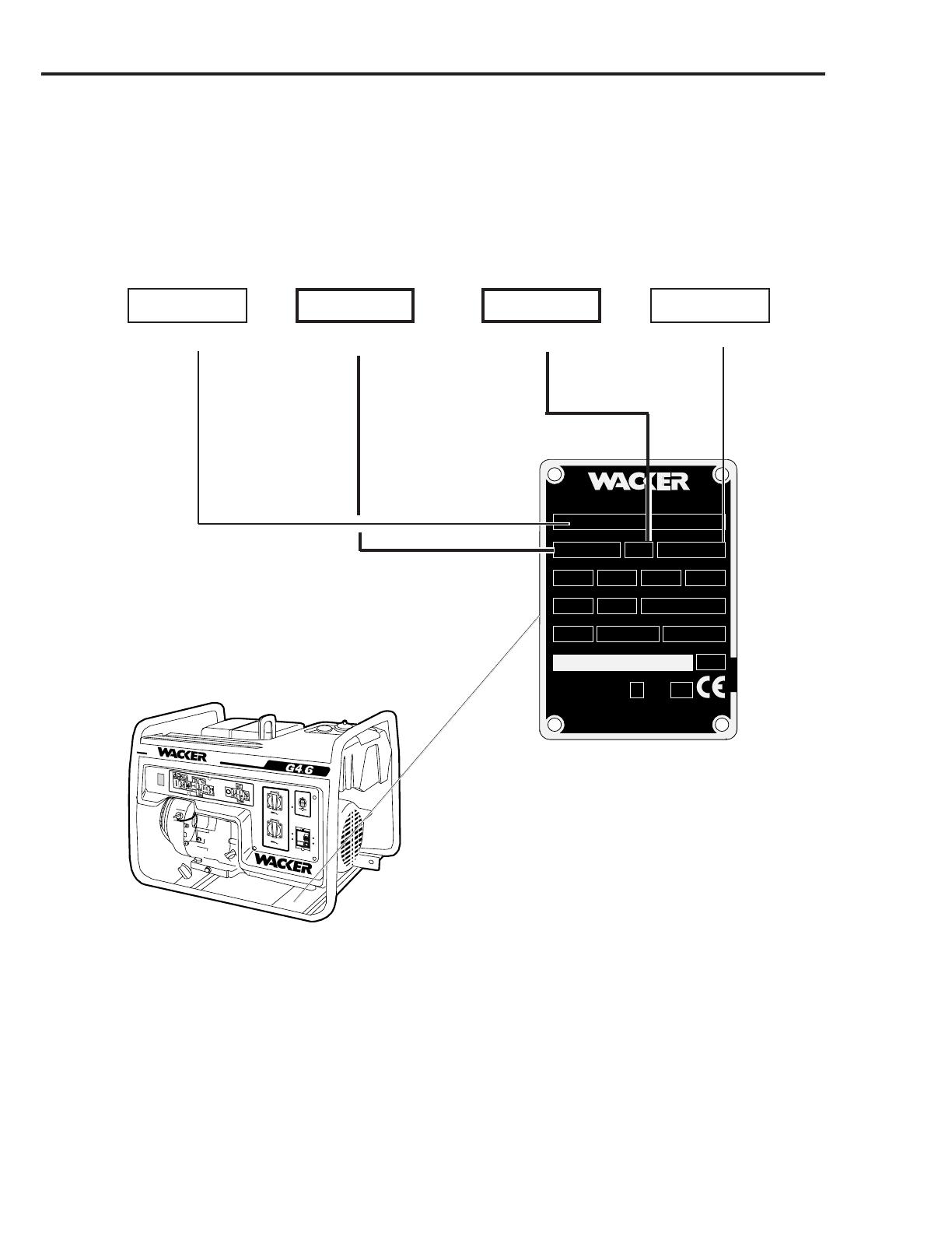
MENOMONEE FALLS, WI USA 53051
110635
Rev. Serial No.
A
kW
hz N/M
Item No.
Vclass
lbs
kg
Model
Man.
Yr.
MADE
IN USA Insul.
Class
GENERATING SET ISO 8528
Serial Number
My machine’s numbers are:
RevisionItem Number
Model number
GS4.6AGS4.6A
GS4.6AGS4.6A
GS4.6A
00082690008269
00082690008269
0008269 101101
101101
101 50101015010101
50101015010101
5010101
Nameplate
A nameplate listing the Model Number, Item Number, Revision, and Serial Number is attached to each unit. Please
record the information found on this plate so it will be available should the nameplate become lost or damaged. When
ordering parts or requesting service information, you will always be asked to specify the model, item number,
revision number, and serial number of the unit.
1031SD44

50 Hz Portable Generators
Repair Manual
Table of Contents
1 Safety
1.1 Safety Notes . . . . . . . . . . . . . . . . . . . . . . . . . . . . . . . . . . . . . . . 1A-1
1.2 Laws Pertaining to Spark Arresters . . . . . . . . . . . . . . . . . . . . . . 1A-1
1.3 Operating Safety . . . . . . . . . . . . . . . . . . . . . . . . . . . . . . . . . . . . 1A-2
1.4 Engine Safety . . . . . . . . . . . . . . . . . . . . . . . . . . . . . . . . . . . . . . 1A-3
1.5 Service Safety . . . . . . . . . . . . . . . . . . . . . . . . . . . . . . . . . . . . . . 1A-3
2 Technical Data
2.1 Generator Specifications . . . . . . . . . . . . . . . . . . . . . . . . . . . . . . 2A-1
2.2 Engine Specifications . . . . . . . . . . . . . . . . . . . . . . . . . . . . . . . . . 2A-2
3 Power Requirements
3.1 Determining Power Requirements . . . . . . . . . . . . . . . . . . . . . . . 3A-1
3.2 Outdoor Installation . . . . . . . . . . . . . . . . . . . . . . . . . . . . . . . . . . 3A-1
3.3 Indoor Installation. . . . . . . . . . . . . . . . . . . . . . . . . . . . . . . . . . . . 3A-1
3.4 Grounding the Generator . . . . . . . . . . . . . . . . . . . . . . . . . . . . . . 3A-2
3.5 Use of Extension Cords . . . . . . . . . . . . . . . . . . . . . . . . . . . . . . . 3A-2
4 Model G2.1A
4.1 Theory of Operation – Capacitor Generators . . . . . . . . . . . . . . . 4A-1
4.2 Rotor . . . . . . . . . . . . . . . . . . . . . . . . . . . . . . . . . . . . . . . . . . . . . 4A-2
4.3 Stator . . . . . . . . . . . . . . . . . . . . . . . . . . . . . . . . . . . . . . . . . . . . . 4A-2
4.4 Capacitor . . . . . . . . . . . . . . . . . . . . . . . . . . . . . . . . . . . . . . . . . . 4A-2
4.5 Diodes . . . . . . . . . . . . . . . . . . . . . . . . . . . . . . . . . . . . . . . . . . . . 4A-2
4.6 Circuit Breaker . . . . . . . . . . . . . . . . . . . . . . . . . . . . . . . . . . . . . . 4A-3
4.7 Earth Leakage Circuit Breaker (ELCB) . . . . . . . . . . . . . . . . . . . 4A-3
4.8 Capacitors . . . . . . . . . . . . . . . . . . . . . . . . . . . . . . . . . . . . . . . . . 4A-4
4.9 Engine Speed . . . . . . . . . . . . . . . . . . . . . . . . . . . . . . . . . . . . . . 4A-4
4.10 Loss of Residual Magnetism in Rotor. . . . . . . . . . . . . . . . . . . . . 4A-5
4.11 Receptacle Panel Wiring . . . . . . . . . . . . . . . . . . . . . . . . . . . . . . 4A-6
4.12 Rotor Diode Testing . . . . . . . . . . . . . . . . . . . . . . . . . . . . . . . . . . 4A-6
4.13 Stator Winding Testing . . . . . . . . . . . . . . . . . . . . . . . . . . . . . . . . 4A-7
4.14 Rotor Winding Testing . . . . . . . . . . . . . . . . . . . . . . . . . . . . . . . . 4A-8
4.15 Generator Disassembly . . . . . . . . . . . . . . . . . . . . . . . . . . . . . . . 4A-9
4.16 Generator Disassembly . . . . . . . . . . . . . . . . . . . . . . . . . . . . . . . 4A-9
4.17 Troubleshooting . . . . . . . . . . . . . . . . . . . . . . . . . . . . . . . . . . . . 4A-10
4.18 Periodic Maintenance Schedule . . . . . . . . . . . . . . . . . . . . . . . . 4A-11
4.19 Storing/Transporting . . . . . . . . . . . . . . . . . . . . . . . . . . . . . . . . 4A-11
4.20 Wiring Schematic (G2.1A Model) . . . . . . . . . . . . . . . . . . . . . . . 4A-12

50 Hz Portable Generators
Repair Manual
Table of Contents, continued
5 Models G3.3A, G4.6A, GS4.6A, & GS5.7A
5.1 Theory of Operation – Brush Generators . . . . . . . . . . . . . . . . . . 5A-1
5.2 Rotor . . . . . . . . . . . . . . . . . . . . . . . . . . . . . . . . . . . . . . . . . . . . . 5A-2
5.3 Stator . . . . . . . . . . . . . . . . . . . . . . . . . . . . . . . . . . . . . . . . . . . . . 5A-2
5.4 Automatic Voltage Regulator (AVR) . . . . . . . . . . . . . . . . . . . . . . 5A-2
5.5 Choke . . . . . . . . . . . . . . . . . . . . . . . . . . . . . . . . . . . . . . . . . . . . 5A-3
5.6 Bridge Rectifier . . . . . . . . . . . . . . . . . . . . . . . . . . . . . . . . . . . . . 5A-3
5.7 Engine Auto Idle Module . . . . . . . . . . . . . . . . . . . . . . . . . . . . . . 5A-3
5.8 Choke Test . . . . . . . . . . . . . . . . . . . . . . . . . . . . . . . . . . . . . . . . 5A-3
5.9 Main Circuit Breaker . . . . . . . . . . . . . . . . . . . . . . . . . . . . . . . . . 5A-4
5.10 Earth Leakage Circuit Breaker (ELCB) . . . . . . . . . . . . . . . . . . . 5A-4
5.11 Engine Speed . . . . . . . . . . . . . . . . . . . . . . . . . . . . . . . . . . . . . . 5A-6
5.12 Auto Idle Switch . . . . . . . . . . . . . . . . . . . . . . . . . . . . . . . . . . . . 5A-7
5.13 Loss of Residual Magnetism in Rotor . . . . . . . . . . . . . . . . . . . . 5A-9
5.14 Diode Bridge . . . . . . . . . . . . . . . . . . . . . . . . . . . . . . . . . . . . . . . 5A-9
5.15 Stator Windings . . . . . . . . . . . . . . . . . . . . . . . . . . . . . . . . . . . . 5A-10
5.16 Rotor Windings . . . . . . . . . . . . . . . . . . . . . . . . . . . . . . . . . . . . 5A-11
5.17 Slip Rings and Brushes . . . . . . . . . . . . . . . . . . . . . . . . . . . . . . 5A-11
5.18 Automatic Voltage Regulator . . . . . . . . . . . . . . . . . . . . . . . . . . 5A-11
5.19 Generator Disassembly. . . . . . . . . . . . . . . . . . . . . . . . . . . . . . 5A-13
5.20 Generator Assembly . . . . . . . . . . . . . . . . . . . . . . . . . . . . . . . . 5A-14
5.21 Troubleshooting . . . . . . . . . . . . . . . . . . . . . . . . . . . . . . . . . . . 5A-15
5.22 Periodic Maintenance Schedule . . . . . . . . . . . . . . . . . . . . . . . 5A-16
5.23 Wiring Schematics – Generator/Engine . . . . . . . . . . . . . . . . . 5A-17
5.24 Storing/Transporting . . . . . . . . . . . . . . . . . . . . . . . . . . . . . . . . 5A-22
1A-1
50 HZ PORTABLE GENERATORS SAFETY 1A
1.2 Laws Pertaining to Spark Arresters
Notice: Some local authorities require that in certain locations, spark arresters be used on internal combustion engines.
A spark arrester is a device designed to prevent the discharge of sparks or flames from the engine exhaust. It is often
required when operating equipment on forested land to reduce the risk of fires. Consult the engine distributor or local
authorities and make sure you comply with regulations regarding spark arresters.
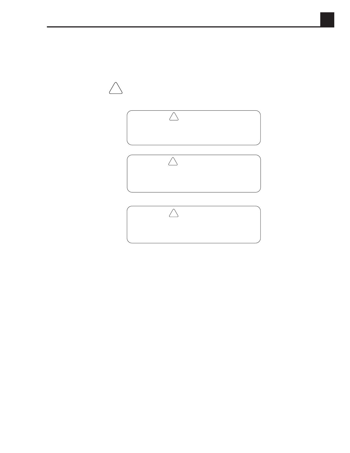
1.1 Safety Information
This manual contains DANGER, WARNING, CAUTION, and NOTE callouts which must be followed to reduce the
possibility of personal injury, damage to the equipment, or improper service.
CAUTION: Used without the safety alert symbol,
CAUTION indicates a potentially hazardous situation
which, if not avoided, may result in property damage.
Note:
Contains additional information
important to a procedure.
This is the safety alert symbol. It is used to alert you to potential
personal injury hazards. Obey all safety messages that follow
this symbol to avoid possible injury or death.
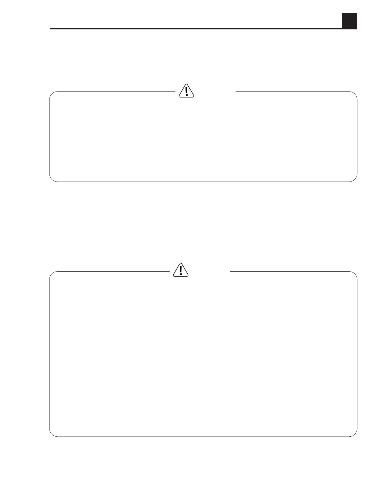
DANGER indicates an imminently hazardous
situation which, if not avoided, will result in
death or serious injury.
CAUTION indicates a potentially hazardous
situation which, if not avoided, may result in
minor or moderate injury.
WARNING indicates a potentially hazardous
situation which, if not avoided, could result in
death or serious injury.
!
WARNING
!
CAUTION
!
!
DANGER

1A-2
1A SAFETY 50 HZ PORTABLE GENERATORS
1.3 Operating Safety
Familiarity and proper training are required for the safe operation of electrical equipment! Equipment operated
improperly or by untrained personnel can be dangerous! Read the operating instructions and familiarize yourself with
the location and proper use of all instruments and controls. Inexperienced operators should receive instruction from
someone familiar with the equipment before being allowed to operate the generator.
WARNING
NEVER operate generator when open containers of
fuel, paint, or other flammable liquids are nearby.
NEVER operate generator, or tools attached to the
generator, with wet hands.
NEVER use worn electrical cords. Severe electrical
shock and equipment damage may result.
NEVER run generator indoors or in an enclosed area
unless adequate ventilation, through such items as
exhaust fans or hoses, is provided. Exhaust gas from
the engine contains poisonous carbon monoxide
gas; exposure to carbon monoxide can cause loss of
consciousness and may lead to death.
NEVER run electrical cords under the generator, or
over vibrating or hot parts.
NEVER enclose or cover generator when in use or
when hot.
NEVER overload generator. The total amperage of
the tools and equipment attached to the generator
must not exceed the load rating of the generator.
NEVER allow untrained personnel to operate or
service the generator. Know how to operate and stop
generator before starting it.
NEVER operate generator in snow, rain, or standing
water.
ALWAYS keep generator at least three feet (one
meter) away from structures, buildings, and other
equipment during use.
ALWAYS keep generator out of reach of children
and pets.
ALWAYS keep the area immediately surrounding
the generator clean, neat and free of debris.
ALWAYS position and operate generator on a firm,
level surface.
ALWAYS remove all tools, cords, and other loose
items from generator before starting it.
ALWAYS make certain generator is well-grounded
and securely fastened to a good earthen ground.
ALWAYS transport generator in an upright position.
BACKFEED FROM THE GENERATOR INTO THE PUBLIC POWER DISTRIBUTION SYSTEM CAN
CAUSE SERIOUS INJURY OR DEATH TO UTILITY WORKERS!
Improper connection of generator to a building’s electrical system can allow electrical current from the generator
to backfeed into utility lines. This could result in electrocution of utility workers, fire, or explosion. Connections to
a building’s electrical system must be made by a qualified electrician and comply with all applicable laws and
electrical codes.
WARNING
1A-3
50 HZ PORTABLE GENERATORS SAFETY 1A
1.4 Engine Safety
Internal combustion engines present special hazards during operation and fueling! Read and follow warning
instructions in engine owner’s manual and safety guidelines below. Failure to follow the safety guidelines described
below could result in severe injury or death.
1.5 Service Safety
Poorly maintained equipment can become a safety hazard! In order for the equipment to operate safely and properly
over a long period of time, periodic maintenance and occasional repairs are necessary. If the generator is experiencing
problems or is being serviced, attach a “DO NOT START” sign to the control panel to notify other people of its condition.
WARNING
NEVER allow water to accumulate around the
base of the generator set. If water is present,
move the generator and allow it to dry before
servicing.
NEVER service generator if clothing or skin is
wet.
NEVER use gasoline or other low flash point
solvents to clean air filter elements.
NEVER allow untrained personnel to service
this equipment. Only trained electrical technicians
should be allowed to service the electrical
components of this equipment.
NEVER modify the equipment without express
written approval from WACKER Corporation.
ALWAYS replace all guards and safety devices
immediately after servicing.
ALWAYS turn engine off before servicing generator.
If engine has electric start, disconnect negative
terminal on battery.
ALWAYS keep generator clean and labels legible.
Replace all missing and hard-to-read labels. Labels
provide important operating instructions and warn of
dangers and hazards.
ALWAYS let engine cool before transporting or
servicing.
ALWAYS remain aware of moving parts and keep
hands, feet, and loose clothing away from moving
parts on generator and engine.
ALWAYS keep fuel lines in good condition and
properly connected. Leaking fuel and fumes are
extremely explosive.
WARNING
DO NOT run engine indoors or in an enclosed area
unless adequate ventilation, through such items as
exhaust fans or hoses, is provided.
DO NOT fill or drain fuel tank near an open flame,
while smoking, or while engine is running.
DO NOT fill fuel tank indoors or in an enclosed area
unless adequate ventilation, through such items as
exhaust fans, is provided.
DO NOT touch or lean against hot exhaust pipes.
DO NOT operate with the fuel tank cap loose or
missing.
DO NOT add fuel to a hot or running engine.
DO NOT start engine if fuel has spilled or an odor of
fuel is present. Move generator away from the spill
and wipe generator dry before starting.

1A-4
1A SAFETY 50 HZ PORTABLE GENERATORS
Notes:
2A-1
50 HZ PORTABLE GENERATORS TECHNICAL DATA 2A
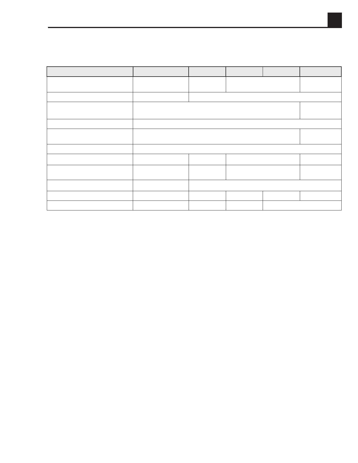
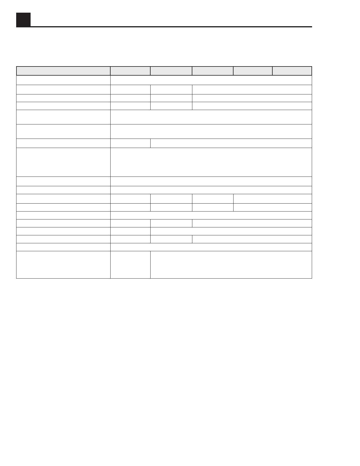
2.1 Generator Specifications
Table 2-1.
ledoM A1.2G A3.3G A6.4G A6.4SG A7.5SG
tuptuOAVk1,23,36,4 Ø11,4
Ø37,5
epyTsselhsurBrotalugeRegatloVcitamotuA
elbaliavasegatloVCA esahp&egatlov V032 esahp1 Ø1V032
Ø3V004
ycneuqerFzH05
rotcaFrewoP0,1 Ø10,1
Ø38,0
selcatpeceRCAlanoitpO
rekaerBtiucriCniaMpma)elop1(01)elop1(51)elop1(02)elop3(9
tnerruCsuounitnoC V004/V032tapma.A.N/1,9.A.N/3,41.A.N/0,022,8/0,81
LxWxH mm 586x544x534586x585x035
)yrd(thgieWgK4417083838
yrettaBA/NA/NA/N02/21/A-L81N-05
2A-2
TECHNICAL DATA 50 HZ PORTABLE GENERATORS
2A
2.2 Engine Specifications
Table 2-2.
ledoM A1.2G A3.3G A6.4G A6.4SG A7.5SG
ekaMenignE adnoH
ledoMenignEXV1K061XG1K042XG1K043XG
mpr0003@rewoPWk1,40,62,8
cibuctnemecalpsiDmc361242733
–deepSgnitarepO
daolon
mpr
05±0013
–deepSgnitarepO
daollluf
mpr
0003±50
deepSeldIotuAmprA/N0022±05
ecnaraelCevlaV
)dloc(
tsuahxe
ekatni
mm02,0
51,0
gulPkrapSepytU-RPE02W/SE6RPB
paGgulPkrapSmm8,0–7,0
retratS)V/epyt(A/NA/NA/NV21/cirtcelE
rotanretlApmaA/NA/NA/N1
leuFepyT)enatcO77.niM(dedaelnuralugeR
noitpmusnoCleuFrh/retil7,14,22,3
yticapaCknaTleuFretil7,35,91
emiTgninnuR.rh2,22,80,6
renaelCriAepytrenaelc-erpmaofdettew-liohtiwepytyrD
noitacirbuLenignE
yticapaC
edarglio
ecivres
ssalc
lm
03W01EAS
ESro,FS,GS
006
03W01EAS
FSroGS
0011
3A-1
50 HZ PORTABLE GENERATORS POWER REQUIREMENTS 3A
3.1 Determining Power
Requirements
These generators are designed to operate single-phase,
50 hertz appliances or tools running at 230 VAC for the
G2.1A, G3.3A, G4.6A, and GS4.6A models, and a single
phase voltage of 230 VAC and a three phase voltage of
400 VAC for the GS5.7A model. Check the nameplate or
label provided on tools and appliances to make sure their
power requirements match the power output of the
generator.
Some appliances and tools require a surge of current
when starting. This means that the amount of power
needed to initially start the equipment is larger than the
power required to keep it running. The generator must be
capable of supplying this “surge” current. Other types of
appliances require more power than is actually stated on
their nameplates.
The chart below is offered only as a general guideline to
help you in determining power requirements for different
types of equipment. Check with your nearest WACKER
Dealer, or contact the manufacturer or dealer of the tool
or appliance, with questions regarding power
requirements.
•Incandescent lights and appliances such as irons
and hot plates use a resistive-type heating element
and require the same wattage to start and run as is
stated on their nameplates.
•Fluorescent and mercury lamps require 1.2 – 2 times
their stated wattage to start.
•Electrical motors and many types of electrical tools
often require a large starting current. The amount of
starting current depends on the type of motor and its
use.
•Most electrical tools require 1.2 – 3 times their stated
wattage for running.
•Loads such as submersible pumps and air compres-
sors require a very large force to start. They need as
much as 3 – 5 times the wattage stated on their
nameplates in order to start.
If the wattage is not given for a particular tool or appli-
ance, it can be calculated by multiplying its voltage and
amperage requirements:
VOLTS x AMPS = WATTS
CAUTION: If a tool or appliance does not reach full
speed within a few seconds when switched on, turn it off
immediately to avoid damage.
CAUTION: When starting loads, DO NOT exceed two
(2) times the given Continuous Current rating for model
G2.1A, or one-and-one-half (1 1/2) times for all other
models, as damage to the generator may occur. See
Section 2.1
Generator Specifications
.
3.2 Outdoor Installation
Place the generator in an area where it will not be
exposed to rain or snow. Make sure it is positioned on
firm, level ground so it will not slide or shift. Position
engine exhaust away from areas where people may be
present.
If operating the generator inside a tunnel or deep trench,
make sure there is adequate ventilation. Precautions
similar to those required when operating indoors may be
necessary.
The surrounding area must be free of water and moisture.
All components must be protected from excessive
moisture.
3.3 Indoor Installation
If the generator must be operated indoors, adequate
ventilation or exhaust hoses must be provided. When
venting exhaust fumes, make sure the exhaust piping is
large enough to prevent excessive back pressure to the
engine. Back pressure reduces engine efficiency and
may cause the engine to overheat.
WARNING
Exhaust gas from the engine contains poisonous
carbon monoxide gas; exposure to carbon monoxide
can cause loss of consciousness and may lead to
death. Never run generator indoors or in an enclosed
area unless adequate ventilation, through such items
as exhaust fans or hoses, is provided.
When operated indoors, steps to prevent fire and explosion
such as, providing a good earthen ground, removing all
flammable materials near generator, and using only
electric cords in good condition, must be observed. See
Section 1.3
Operating Safety.
3A-2
3A POWER REQUIREMENTS 50 HZ PORTABLE GENERATORS
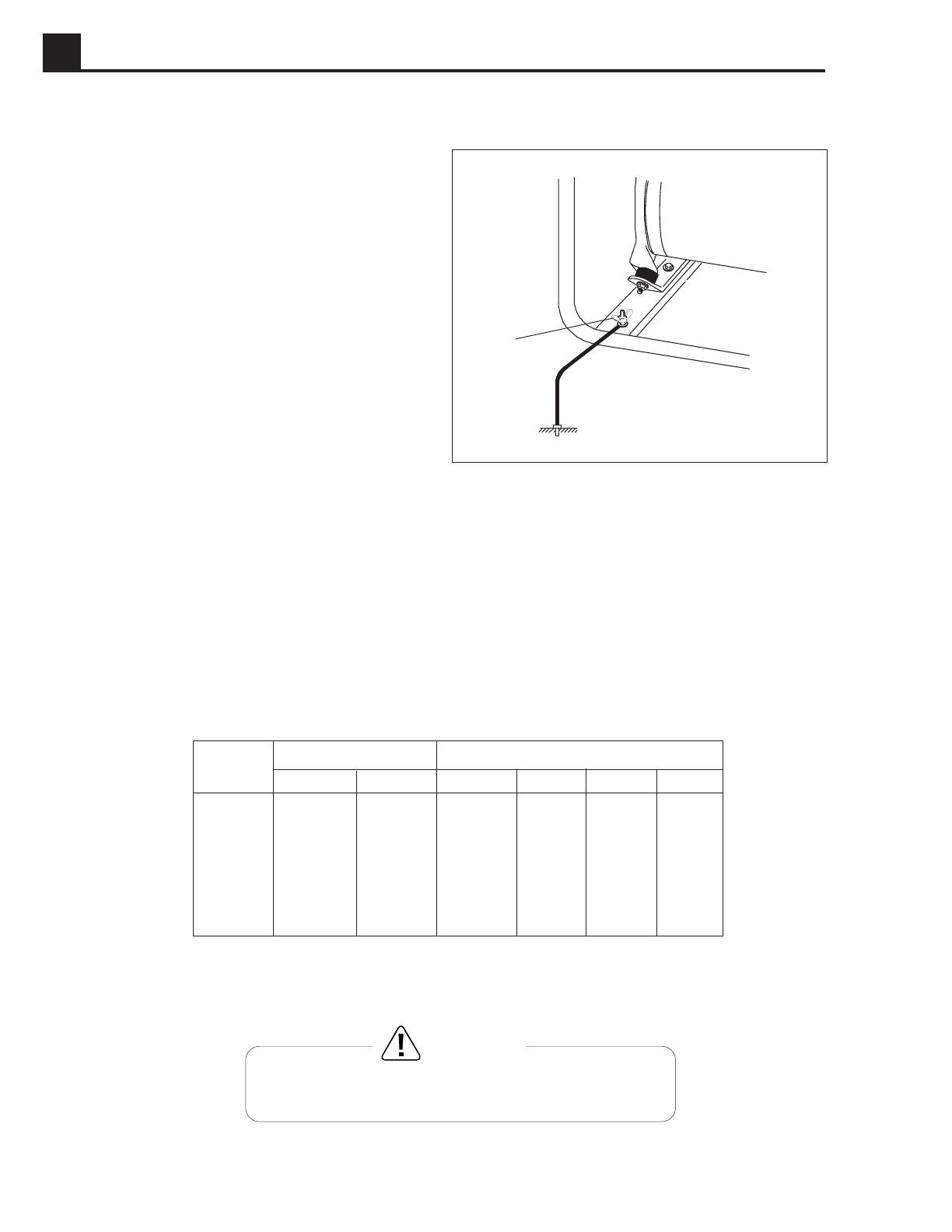
3.4 Grounding the Generator
The generator should be grounded to a good ground
source in compliance with National Electric Code stand-
ards and local regulations.
Use #8 wire and secure one end to the ground terminal
(a) provided on the generator frame and the other end to
a suitable ground source. See Figure 3-1.
3.5 Use of Extension Cords
When a long extension cord is used to connect an appliance or tool to the generator, a voltage loss occurs – the longer
the cord, the greater the voltage loss. This results in less voltage being supplied to the appliance or tool and increases
the amount of current draw or reduces performance. A heavier cord with a larger wire size will reduce the voltage loss.
Use Table 3-1 below as a guide for selecting proper cable size.
Use only extension cords rated for outdoor use and equipped with a third-wire ground.
Current Load in Watts Maximum Cable Length in Ft.
Amps 120V 240V #10 #12 #14 #16
2.5 300 600 1000 ft. 600 ft. 375 ft. 250 ft.
5 600 1200 500 ft. 300 ft. 200 ft. 125 ft.
7.5 900 1800 350 ft. 200 ft. 125 ft. 100 ft.
10 1200 2400 250 ft. 150 ft. 100 ft.
15 1800 3600 150 ft. 100 ft. 65 ft.
20 2400 4800 125 ft. 75 ft. 50 ft.
1001SD02
Keep electrical cords in good condition. DO NOT use worn,
bare, or frayed cords which can cause electrical shock.
WARNING
a
CAUTION: Operating equipment at low voltage can cause overheating.
Figure 3-1. Grounding
Table 3-1.
4A-1
50 HZ PORTABLE GENERATORS G2.1A/G2.1AE 4A
4.1 Theory of Operation –Capacitor Generators
Brushless Generator
This model generator uses a brushless design to generate
and regulate power. It consists of a rotor, stator, diodes,
and an auxiliary winding. The brushless generator also
contains a capacitor that is connected to the auxiliary
winding. Its purpose is to regulate the voltage in the main
windings and prevent a voltage drop when a load is
applied.
This generator is designed to operate with single phase
loads at or near a power factor of 1.0. The principle of
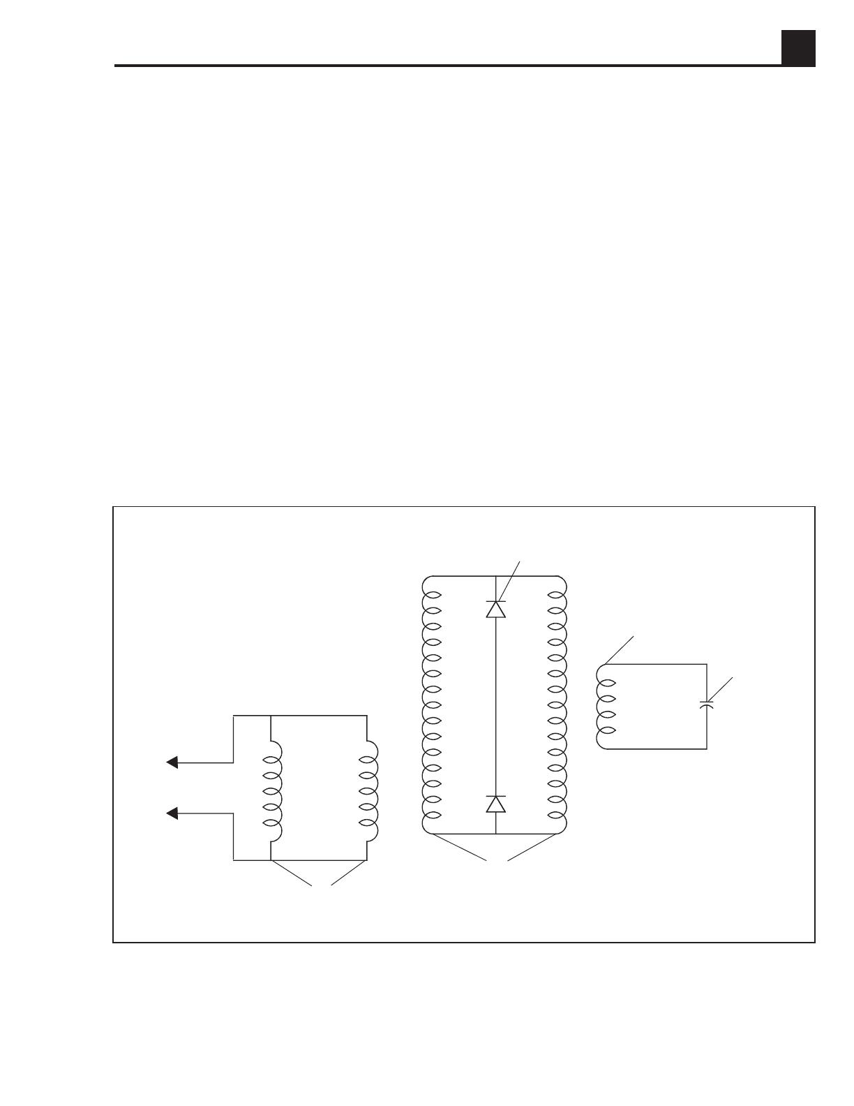
operation is schematically represented in Figure 4-1, and
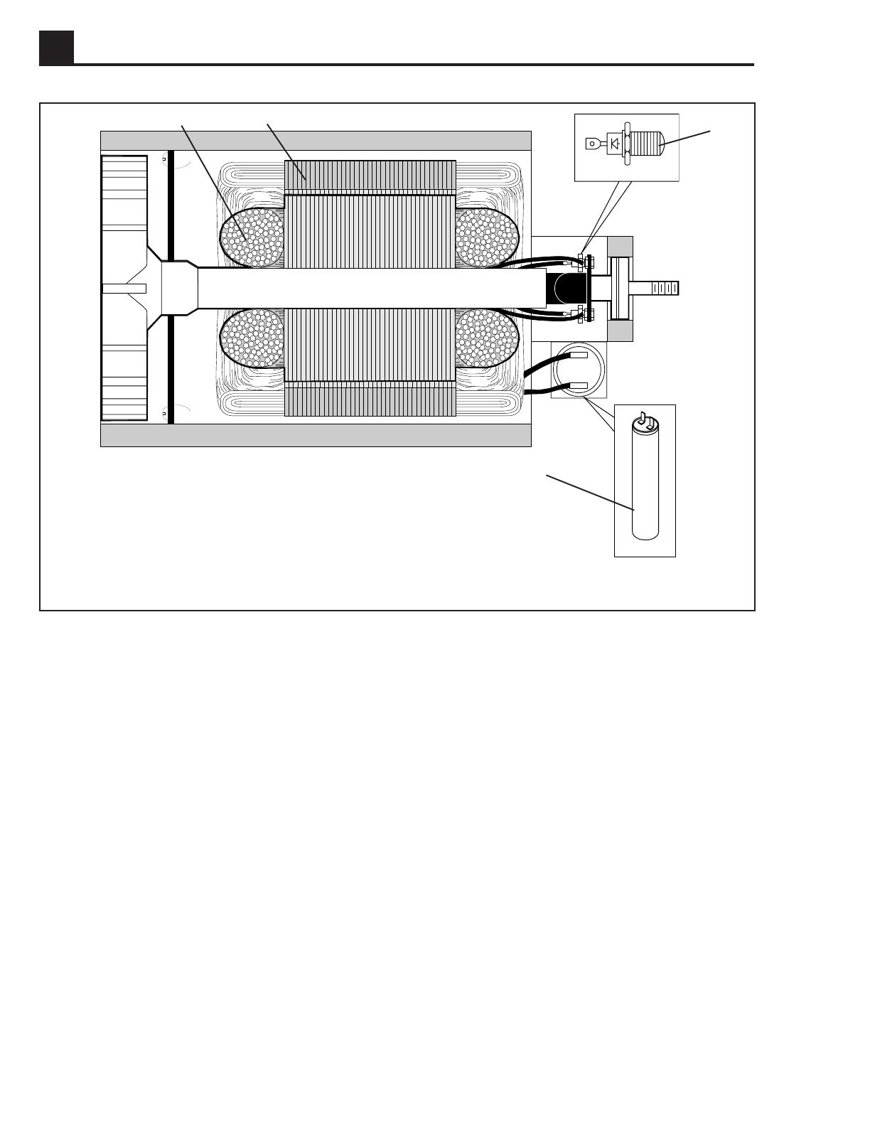
a cross-sectional view in Figure 4-2. The auxiliary
winding (a), in conjunction with the capacitor, provide
excitation by inducing current in the rotor windings (b)
which is rectified by the diodes (c) to produce direct
current. The main stator winding (d) is designed for
parallel connection to give a voltage output with no
voltage adjustment possible.
Figure 4-1. Principle of Operation Schematic
1023SD44
d
Main Windings
b
Rotor Field
Windings
Capacitor
aAuxiliary Winding
cDiodes
(Rectifier)
Basic Generator Theory
Wacker air-cooled generators work on the principle of
electromagnetic induction i.e., the cutting of magnetic
lines of force by a coil of wire to produce an electric
voltage in the coil of wire.
The two main components of the generator, the rotor and
stator, are the key. The rotor acts as the magnet and the
stator acts as the coil of wire. As the rotor rotates, its
magnetic lines of force are cut by the coils of wire in the
stationary stator. The voltage induced in the windings of
the stator is tapped off and available at the receptacles.
4A-2
4A G2.1A/G2.1AE 50 HZ PORTABLE GENERATORS
Figure 4-2. Brushless Type Generator
4.2 Rotor (a)
The inside of the rotor shaft is tapered and connected
directly to the taper on the engine crankshaft. This end is
supported by the engine crankshaft bearing. The oppo-
site end of the rotor is supported by a bearing installed in
the generator housing. This end also contains the two
diodes mounted on the diode bracket assembly. There
are two individual coils wound on the rotor. When the
engine is running, these two windings create the mag-
netic field for the main stator windings.
4.3 Stator (b)
The stator houses both the main windings and auxiliary
winding. The main windings are connected directly to the
main circuit breaker to supply power to the output recep-
tacles. The auxiliary winding induces the initial voltage in
the field windings of the rotor and regulates the voltage.
It is connected directly to the main capacitor.
4.4 Capacitor (c)
A capacitor is connected in series with the auxiliary
winding. Its purpose is to regulate the voltage when a
load is applied.
4.5 Diodes (d)
Two diodes are located on the rotor. These diodes form
a half wave rectifier to convert the induced AC voltage in
the rotor windings to DC voltage.
1022SD88
b
ad
c
4A-3
50 HZ PORTABLE GENERATORS G2.1A/G2.1AE 4A
230V 230V
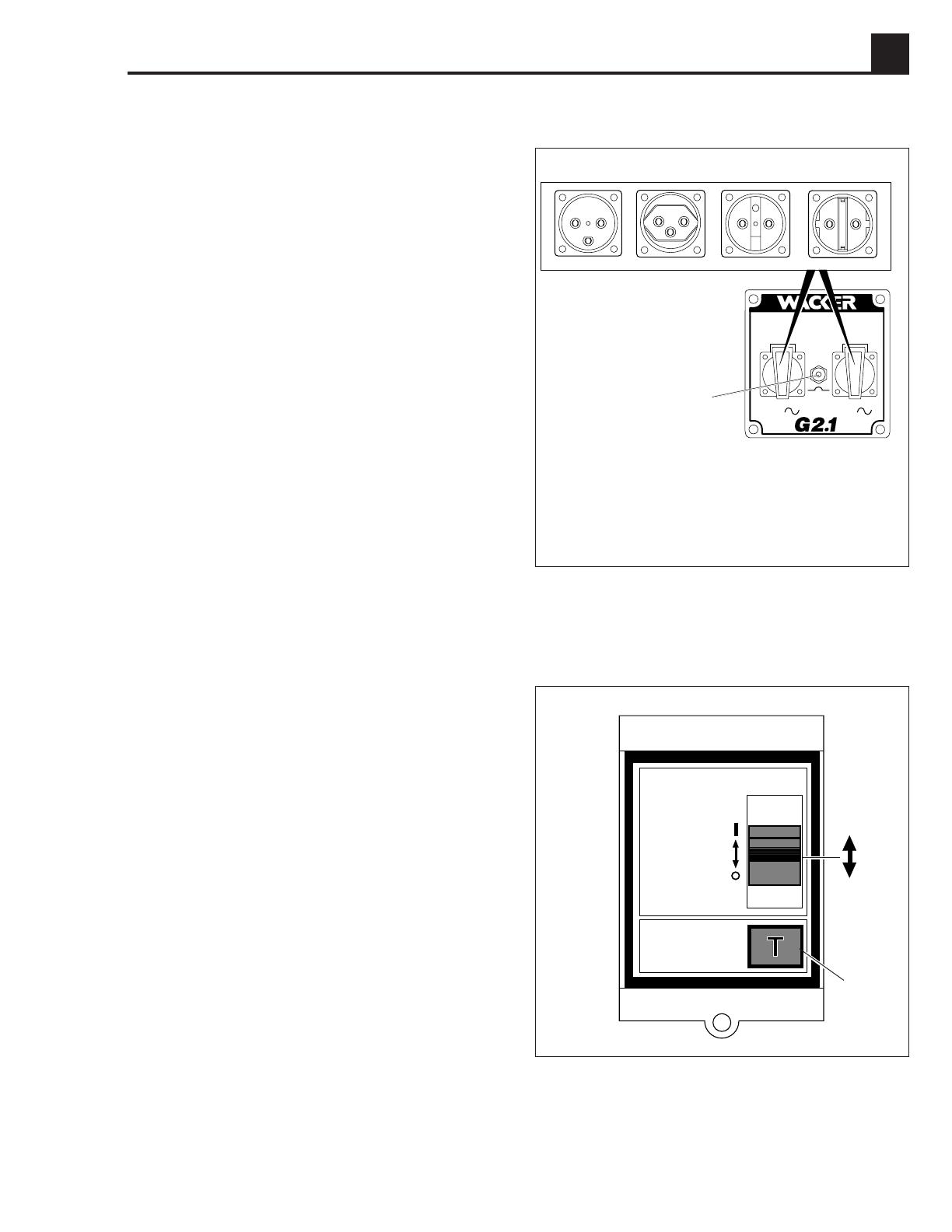
4.6 Control Panel
The generator is protected by a 10 amp circuit breaker
(a) located on the control panel.
The circuit breaker protects the generator from severe
overloads or short circuits. If the circuit breaker opens,
turn the engine off immediately and determine the cause
before restarting. Check the appliances and tools at-
tached to the generator for defects and make sure their
power requirements do not exceed the power rating of
the generator.
When the circuit breaker opens, the breaker button will
pop out. To reset circuit breaker, push button in.
Depending on model, the generator will have one of the
four styles of receptacles, the Danish IP44 type (b), the
Swiss IP X4 type (c), the France/Belgium IP44 type (d),
or the Schuko IP44 (CEE 7) type (e).
Note:
Enlargements of receptacles show protective
covers removed for identification purposes only. Never
remove protective covers.
4.7 Earth-leakage Circuit Breaker
Generator model G2.1AE is equipped with an earth-
leakage circuit breaker. The circuit breaker is current
operated and shuts off the power to the receptacles when
a ground fault of 30 milli-Amps or greater occurs in the
generator or to a piece of equipment attached to the
generator. The circuit breaker is located on the opposite
side of the generator as the control panel.
The circuit breaker should be tested for proper operation
every time the generator is used.
To test the earth-leakage circuit breaker:
Start the generator. Place main circuit breaker in closed
position. Push in TEST button (g). The circuit breaker
lever will lower to the open position (f2). Power is now off
at both receptacles. If the lever does not lower, the circuit
breaker is not working. Do not use the generator until the
problem can be corrected. To restore power to the
receptacles, raise the circuit breaker lever to the closed
position (f1).
If the circuit breaker lever lowers to the open position
during operation, stop the generator and check it and
equipment for defects. Repair all defects before operat-
ing generator.
1020SD80
T
E
S
T
g
f1
f2
bc
Control Panel
aMain circuit breaker - 10 Amp.
bDanish IP44 style receptacle.
cSwiss IP X4 style receptacle.
dFrance/Belgium IP44 style receptacle.
eSchuko IP44 (CEE 7) style receptacle.
a
de
1031SD43

4A-4
4A G2.1A/G2.1AE 50 HZ PORTABLE GENERATORS
Figure 4-4. Testing Capacitor
4.8 Capacitors
Testing Capacitor
1. Discharge capacitor as described above, then
disconnect all wire leads from the terminals.
2. Check the capacitor charge and discharge readings
using an ohmmeter as described below or use a
capacitor checker. See Figure 4-4.
Set Ohmmeter on R x 10k scale.
Set meter leads on capacitor terminals. The meter
should deflect momentarily towards zero (fully
discharged) and then slowly climb up to infinity
(charging).
Reverse meter leads and repeat procedure. Results
should be the same.
3. If meter does not deflect torward zero, or deflects to
zero and remains there, the capacitor is open or
shorted and must be replaced.
ALWAYS handle or test capacitors with the engine
stopped. Extremely high voltage is present at the
capacitor terminals while the generator is in use.
Although the capacitors used in this generator are
designed to discharge when the engine is stopped,
it is still a good idea to discharge them manually
before handling. To discharge a capacitor, place a
conductor, such as a screwdriver with an insulated
handle, across the capacitor terminals. Be sure to
touch only the insulated handle. This will short out
across the terminals and discharge the capacitor.
WARNING
1007SD87
4.9 Engine Speed
All generators require a fixed engine speed to maintain
the correct voltage output. Engine speed is controlled by
a governor which automatically adjusts to varying loads
on the engine to maintain a constant speed of 3000 –
3100 rpm.
Testing Engine Speed
Measure the engine speed using a tachometer with no
load applied to the generator. The engine must be
running at 3100 ± 50 rpm. Voltage output is directly
related to engine speed. A slow engine will reduce
voltage. Refer to the Operator’s Manual for engine speed
adjustment.
The generator is designed to produce no output if
engine rpm falls 10% or more below the required
speed (approximately 2700 rpm).
Setting Engine Speed
Setting the engine speed requires the adjustment to the
governor. See Figure 4-5.
To set the engine to the proper speed:
Turn the engine speed adjusting screw (a) in or out
to obtain a no-load speed of 3100 rpm.
CAUTION: Setting the engine speed too high or too low
may damage tools and other appliances attached to the
generator.
1001SD15
Figure 4-5. Engine Speed Adjusting Screw
a
4A-5
50 HZ PORTABLE GENERATORS G2.1A/G2.1AE 4A
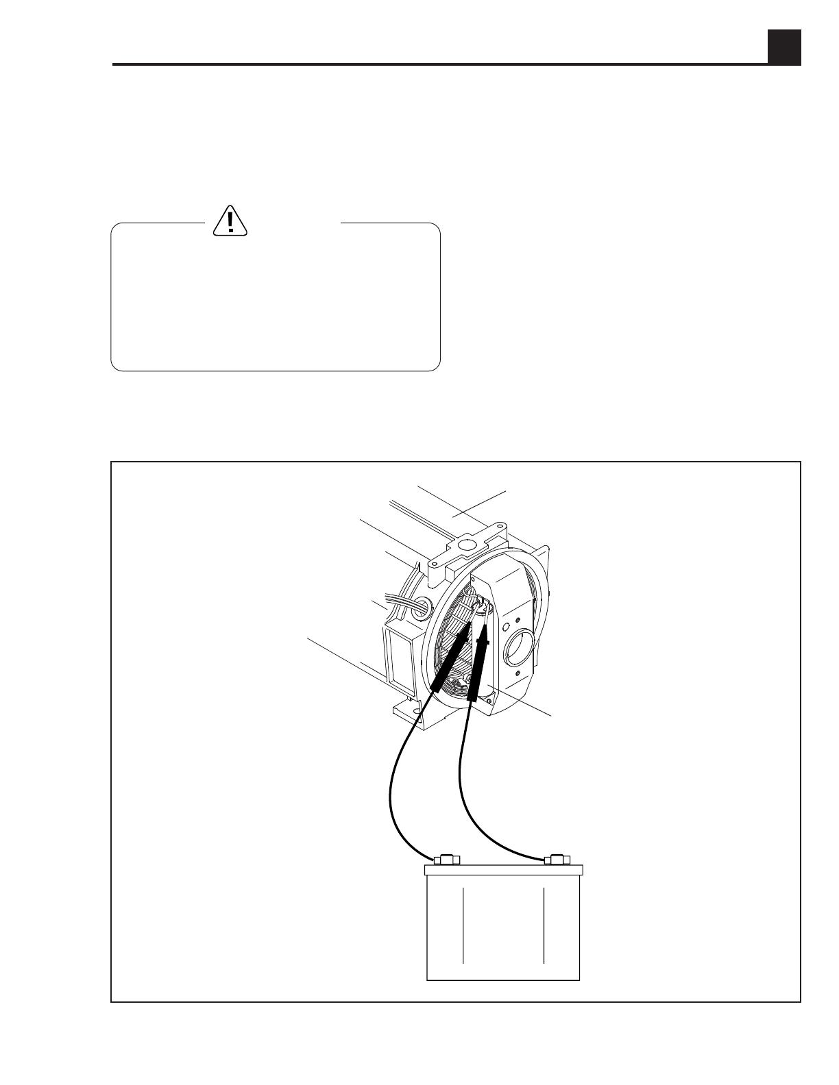
4.10 Loss of Residual Magnetism in Rotor
Contact with exposed connections inside the control
box or while handling battery leads can cause se-
vere electrical shocks. Be extremely careful to avoid
touching any exposed connections. Never wear
jewelry or use tools or metal items that may make
contact across exposed connections. Review safety
rules at beginning of this manual.
WARNING
Figure 4-6. “Flashing” the Rotor
To restore magnetism to the rotor, “flash” it as follows:
1. Remove the two screws and the end cover. Locate the
capacitor that is attached to the stator housing.
2. Run generator at normal no-load speed – 3100 rpm,
auto-idle off.
3. Briefly touch a 12 VDC battery across the two capacitor
connections to pulse the auxiliary winding. The leads
should remain attached to capacitor. The polarity of
the battery leads is not important.
CAUTION: DO NOT hold battery leads on connection
longer than two seconds.
The output voltage should quickly come up to normal
levels. Repeat if necessary. See Figure 4-6.
4. Stop engine and replace end cover.
1023SD45
Capacitor
Stator Hous-
ing
12 VDC
Battery
If the rotor has been removed, or the generator has been
stored over six months, the rotor’s magnetism may be
lost. Loss of magnetism will prevent the generator from
building voltage.

4A-6
4A G2.1A/G2.1AE 50 HZ PORTABLE GENERATORS
4.11 Receptacle Panel Wiring
Remove receptacle panel from control box and inspect
the wiring for worn or loose wires. Make sure all wire
connections are secure and tight at the screws. DO NOT
allow wires to be pinched, kinked or damaged in any
way. Inspect for tight connections at circuit breakers,
capacitors, switches and receptacles. Replace any
broken or damaged parts.
Figure 4-7. Rotor Diode Testing
1024SD03
A zero reading in both directions indicates a shorted
diode. A reading of Infinity in both directions indicates an
open diode. The diode must be replaced in either case.
If one diode is defective it is recommended that both
diodes be replaced since the remaining diode may have
been weakened.
To remove diode, use a soldering iron to soften solder
and remove wires.
When soldering on wires do not allow soldering iron to
remain on diodes longer than 10 seconds or diode may
be damaged.
4.12 Rotor Diode Testing
To check diode:
1. Disassemble generator and remove rotor. See Section
4.15
Generator Disassembly
.
2. Set ohmmeter in lowest scale. Test diode in forward
position. Meter should read low or close to zero.
3. Reverse meter leads and test diode in reverse position.
Meter should read high or close to infinity.
POS
NEGPOS
NEG
HIGH VALUE LOW VALUE
/