Konica Minolta bizhub C220 Series Installation guide
- Category
- Multifunctionals
- Type
- Installation guide
This manual is also suitable for
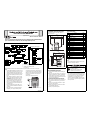
Konica Minolta bizhub C220 Series can handle various paper sizes and types, from small A6 to large A3 and banner paper, and supports weights from 60 to 169gsm, offering flexible paper handling options. It also features a large touch panel for easy control and operation, allowing intuitive access to various functions and settings. Additionally, the bizhub C220 Series offers various connectivity options, including USB, Ethernet, and Wi-Fi, enabling seamless integration into your existing office network or setup.
Konica Minolta bizhub C220 Series can handle various paper sizes and types, from small A6 to large A3 and banner paper, and supports weights from 60 to 169gsm, offering flexible paper handling options. It also features a large touch panel for easy control and operation, allowing intuitive access to various functions and settings. Additionally, the bizhub C220 Series offers various connectivity options, including USB, Ethernet, and Wi-Fi, enabling seamless integration into your existing office network or setup.


-
 1
1
-
 2
2
-
 3
3
-
 4
4
-
 5
5
-
 6
6
-
 7
7
-
 8
8


Konica Minolta bizhub C220 Series Installation guide
- Category
- Multifunctionals
- Type
- Installation guide
- This manual is also suitable for
Konica Minolta bizhub C220 Series can handle various paper sizes and types, from small A6 to large A3 and banner paper, and supports weights from 60 to 169gsm, offering flexible paper handling options. It also features a large touch panel for easy control and operation, allowing intuitive access to various functions and settings. Additionally, the bizhub C220 Series offers various connectivity options, including USB, Ethernet, and Wi-Fi, enabling seamless integration into your existing office network or setup.
Ask a question and I''ll find the answer in the document
Finding information in a document is now easier with AI
Related papers
Other documents
-
Minolta CF2002 User manual
-
-
-
KYOCERA CS 8000i User manual
-
Olivetti D-COPIA 8000 Owner's manual
-
KYOCERA TASKalfa 5500i Operating instructions
-
Copystar CS 3500i Operating instructions
-
Triumph-Adler DC 2435 User manual
-
Utax CD 1435 User manual
-
KYOCERA KM-C1530 User manual