
Rev 3.0/9-21 #35186AFT1
INTENDED FOR USE BY SKILLED
PROFESSIONALS • READ AND
UNDERSTAND BEFORE ASSEMBLING/
INSTALLING
INSTRUCTIONS
MANUAL 908 W. Main • P.O. Box 368
Laurel, MT USA 59044
800-548-7341 (phone)
406-628-8231 (phone)
406-628-8354 (fax)
www.WPG.com
KEEP FOR FUTURE REFERENCE
PAD FRAME EXTENSION KIT, ROCKER ARMS FOR MRTALP-DC3 LIFTERS
Stock numbers: 97463, 97464

#35186AFT Rev 3.0/9-212

Rev 3.0/9-21 #35186AFT1
SPECIFICATIONS .....................................................................................2
FEATURES...............................................................................................3
ASSEMBLY..............................................................................................6
TO CHANGE THE PAD FRAME CONFIGURATION ..................................................6
TO INSTALL/REMOVE EXTENSION KIT...............................................................9
TO INSTALL/REMOVE ROCKER ARMS .............................................................12
TO INSTALL/REMOVE T-ARM ASSEMBLIES ......................................................13
TO CONNECT/DISCONNECT VACUUM HOSES ...................................................14
REPLACEMENT PARTS...........................................................................15
LIMITED WARRANTY ............................................................................16
TO OBTAIN REPAIRS OR WARRANTY SERVICE...................................................16
TABLE OF CONTENTS

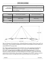
Stock Numbers/
Product Descriptions
97464 (Extension Kit): This option enables an MRTALP-DC3 lifter to handle long loads in the flat
orientation.1
1...... An MRTALP-DC lifter equipped with an Extension Kit (with or without Rocker Arms) can used to handle loads positioned on inclines up to a 4/12 pitch.
97463 (Rocker Arms): This option enables an MRTALP-DC3 lifter to handle loads with increased
weight and length in the flat orientation.
Note: This option requires use of Extension Kit (#97464) and an addition set of T-Arm Assemblies
(#97465 or #97465HV)
Adjusted Maximum
Pad Spread1
1...... See “TO CHANGE THE PAD FRAME CONFIGURATION” for dimensions of various configurations.
Extension Kit, Rocker Arms
and 2 sets of T-Arm Assemblies
Extension Kit
and 1 set of T-Arm Assemblies
with VPSF625 pads 37" x 392½" [94 cm x 997 cm] 37" x 324¾" [94 cm x 825 cm]
with VPSF10T pads 45" x 378" [114 cm x 960 cm] 45" x 310¼" [114 cm x 788 cm]
Adjusted Maximum
Load Capacity 1100 lbs [500 kg] 600 lbs [270 kg]
Weight
Increase2
2...... This weight should be added to the Lifter Weight when determining hoisting equipment capacity.
225 lbs [102 kg] 100 lbs [46 kg]
#35186AFT Rev 3.0/9-212
Note: An Extension Kit (including slings, shackles & lift spool assembly), Rocker Arms and 2 sets
of Pad Frame T-Arm Assemblies equipped with VPFS625 vacuum pads are shown installed on a
model MRTALP-DC3 vacuum lifter.
Note: Before installing the Extension Kit and Rocker Arms read, understand and follow the
lifter’s OPERATING INSTRUCTIONS and the T-Arm Assemblies INSTRUCTIONS MANUAL
(#35178AFT) except when directed differently in these option instructions. Intended use,
operation, storage, inspections, tests and maintenance in the lifter’s instructions should be
understood to include options, when relevant. All warnings in the “SAFETY” section, as well as
alerts in other sections, are applicable when using the Extension Kit and Rocker Arms.
SPECIFICATIONS

Rev 3.0/9-21 #35186AFT3
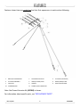
Features shown here are underlined on their first appearance in each section following.
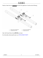
1 MALE QUICK CONNECTOR 2 COTTERLESS HITCH PIN 3 LIFT POINT (TOP SPOOL)
4 LIFT SPOOL ASSEMBLY 5 LONG (OUTSIDE) SLING 6 SHORT (INSIDE) SLING
7 CLEVIS PIN 8 HAIRPIN 9 LONG SLING PIN HOLE
10 EXTENSION ARM 11 FEMALE QUICK CONNECTOR
Note: Pad Frame Extension Kit (#97464) is shown.
For information about specific parts, see “REPLACEMENT PARTS”.
FEATURES

#35186AFT Rev 3.0/9-214
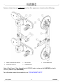
Features shown here are underlined on their first appearance in each section following.
1 FEMALE QUICK CONNECTOR 2 MALE QUICK CONNECTOR
3 COTTERLESS HITCH PIN 4ROCKER ARM TUBE
Note: Pad Frame Rocker Arms (#97463) are shown.
For information about specific parts, see “REPLACEMENT PARTS”.
FEATURES

Rev 3.0/9-21 #35186AFT5
Features shown here are underlined on their first appearance in each section following.
1 SLIDING / MOVABLE PAD MOUNT 2VACUUM PAD 3 QUICK CONNECTOR
4 COTTERLESS HITCH PIN 5 EXTENSION ARM
Note: A Pad Frame T-Arm Assembly with VPSF625 pads is shown at left (#97465) and with
VPSF10T pads at right (#97465HV).
For information about the assemblies, see “REPLACEMENT PARTS”.
FEATURES

#35186AFT Rev 3.0/9-216
ASSEMBLY
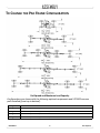
TO CHANGE THE PAD FRAME CONFIGURATION
Pad Spread and Maximum Load Capacity
Configurations are shown with the following optional components and VPFS625 vacuum
pads installed (from top to bottom):
Configuration 1 1 set of T-Arm Assemblies
Configuration 2 Extension Kit (2 arms in use) and 1 set of T-Arm Assemblies
Configuration 3 Extension Kit (2 arms in use), Rocker Arms, and 2 sets of T-Arm Assemblies
Configuration 4 Extension Kit (4 arms in use) and 1 set of T-Arm Assemblies
Configuration 5 Extension Kit (4 arms in use), Rocker Arms, and 2 sets of T-Arm Assemblies

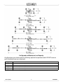
Pad Spread and Maximum Load Capacity
Configurations are shown with the following optional components and VPFS10T vacuum
pads installed (from top to bottom):
Configuration 1 1 set of T-Arm Assemblies
Configuration 2 Extension Kit (2 arms in use) and 1 set of T-Arm Assemblies
Configuration 3 Extension Kit (2 arms in use), Rocker Arms, and 2 sets of T-Arm Assemblies
Configuration 4 Extension Kit (4 arms in use) and 1 set of T-Arm Assemblies
Configuration 5 Extension Kit (4 arms in use), Rocker Arms, and 2 sets of T-Arm Assemblies
Rev 3.0/9-21 #35186AFT7
ASSEMBLY

#35186AFT Rev 3.0/9-218
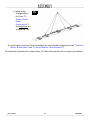
These optional components offer a variety of configurations that enable the lifter to match
different dimensions and weights of rigid roof panels and similar loads. The illustrations on the
two preceding pages show all approved configurations.
Choose an approved configuration to maximize support across the load surface and minimize
load overhang (see “LOAD CHARACTERISTICS” in the lifter’s OPERATING INSTRUCTIONS).
The pad frame configuration selected must be appropriate, both for the weight and for the
dimensions of the load in question (see “SPECIFICATIONS” and configuration illustrations).
Install or remove extension arms, rocker arms and T-arm assemblies as necessary to support the
load adequately (see following sections).
Note: Separate INSTRUCTIONS FOR USE (#35178AFT) are provided with the T-arm assemblies;
read and understand these instructions before employing them.
Always arrange the vacuum pads in a symmetrical configuration about the MRTALP-DC3's main
pad frame, to keep the lifter balanced.
Never use a sling that has knots, twists or
wear that could compromise its strength.
Never use a sling if the capacity tag is
missing or unreadable.
To prevent lifter damage when using
the extension kit (and rocker arms),
always use the kit’s lift spool assembly
and slings regardless of the
configuration selected.
Securely position vacuum hoses to avoid
damage during lifter operation.
After changing the configuration,
suspend the lifter from a crane as
directed in the “ASSEMBLY” section of
the lifter’s OPERATING INSTRUCTIONS.
ASSEMBLY

Rev 3.0/9-21 #35186AFT9
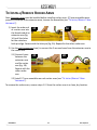
TO INSTALL/REMOVE EXTENSION KIT
1) Remove any pad frame extensions and/or T-arm assemblies from the vacuum lifter (see
“TO INSTALL/REMOVE T-ARM ASSEMBLIES”).
2) Set the lifter down, as directed in the lifter’s OPERATING INSTRUCTIONS.
3) Install one extension arm on the lifter’s pad frame in a similar way to that described in “TO
INSTALL/REMOVE T-ARM ASSEMBLIES”. Repeat with another extension arm.
Note: Consult the configuration illustrations for correct orientation of the extension arms
(see “TO CHANGE THE PAD FRAME CONFIGURATION”).
Note: Make sure to connect corresponding vacuum hoses correctly (see “TO CONNECT/
DISCONNECT VACUUM HOSES”).
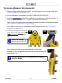
4)
4A 4B
Attach the hoisting hook to the lift
point, which is the top spool of the
lift spool assembly (circled in fig.
4A).
Make sure hook has
restraining latch (fig. 4B).
4C
Note: Some hooks may not be compatible with the lift spool
assembly. If not, use rigging as needed to connect the hook with the
top spool (fig. 4C).1
Use only rigging rated to carry Maximum Load Capacity
plus Lifter Weight.
ASSEMBLY

#35186AFT Rev 3.0/9-2110
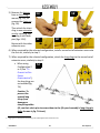
5)
5A 5B
5C 5D 5E
Remove the hairpin
from a short sling’s
mount (fig. 5A), to
remove the clevis pin
(fig. 5B).
Then attach the short
sling to one extension
arm by installing and
securing it with both
pins (figs. 5C-E).
Repeat with the other
extension arm.
6) When required for the selected configuration, install a second set of extension arms onto
the first set, similarly to step 3.
7) When required for the selected configuration, attach the long slings to the second set of
extension arms, similarly to step 5.
•
7A
When using
Configuration 2
or 3 (see “TO
CHANGE THE PAD
FRAME
CONFIGURATION”),
the long slings are
not needed (fig.
7A).
Caution: To
prevent the
unused long
slings from
damage or
interfering with a
lift, use their clevis pins to secure them to the lift spool assembly’s long sling pin
holes (arrows in fig. 7A inset).
1..... Rigging for use directly with the hoisting hook is not supplied with the extension kit.
ASSEMBLY

Rev 3.0/9-21 #35186AFT11
•
7B
When using
Configuration 4
or 5 (see “TO
CHANGE THE PAD
FRAME
CONFIGURATION”),
the long slings are
needed (fig. 7B).
8) Install rocker arms and T-arm assemblies per the selected configuration (see “TO INSTALL/
REMOVE ROCKER ARMS” and “TO INSTALL/REMOVE T-ARM ASSEMBLIES”).
To remove the extension kit, reverse steps 1-8. Store the extension kit in a clean, dry location.
ASSEMBLY

#35186AFT Rev 3.0/9-2112
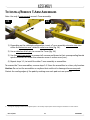
TO INSTALL/REMOVE ROCKER ARMS
Note: Extension arms must be installed before installing rocker arms. If T-arm assemblies were
previously installed in the extension arms, remove the assemblies (see “TO INSTALL/REMOVE T-ARM
ASSEMBLIES”).
1)
1A 2A
Insert the male end
of a rocker arm into
the female end of an
extension arm (fig.
1A) until the holes
for the cotterless
hitch pin align. Secure with the hitch pin (fig. 2A). Repeat for the other rocker arm.
2) Use the quick connectors (see ) to connect the 2 vacuum hoses from the extension arm to
the rocker arm:
2.1)
2A 2B
Connect hoses
between the
extension arm
and the rocker
arm (fig. 1B).
Repeat with the
other rocker
arm.
2.2) Install 2 T-arm assemblies on each rocker arms (see “TO INSTALL/REMOVE T-ARM
ASSEMBLIES”).
To remove the rocker arms, reverse steps 1-2. Store the rocker arms in a clean, dry location.
ASSEMBLY

Rev 3.0/9-21 #35186AFT13
TO INSTALL/REMOVE T-ARM ASSEMBLIES
1A 2A
Note: Use only 2 vacuum pads on each T-arm assembly.
1) Depending on the selected configuration, insert a T-arm assembly extension arm into
either the extension arm’s tube or rocker arm tube (fig. 1A).
2) Use a cotterless hitch pin, to secure the T-arm (fig. 2A).
3) Use the quick connectors to connect all vacuum pad hoses to their corresponding female
quick connectors on either the extension arms or rocker arms (see ).
4) Repeat steps 1-3, to install the other T-arm assembly or assemblies.
To remove the T-arm assemblies, reverse steps 1-4. Store the assemblies in a clean, dry location.
Caution: Do not set the assemblies on surfaces that could soil or damage the vacuum pads.
Protect the sealing edges of the pads by making sure each pad rests on spacers.1
1..... The original shipping container has integrated spacers. Use similarly shaped spacers when setting the assemblies on other surfaces.
ASSEMBLY

1A 2A
#35186AFT Rev 3.0/9-2114
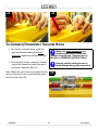
TO CONNECT/DISCONNECT VACUUM HOSES
•
Make sure quick connectors seal
completely and all vacuum hoses
function correctly (see “Vacuum Test” in
the lifter’s OPERATING INSTRUCTIONS).
Securely position vacuum hoses to
avoid damage during lifter operation.
To connect a vacuum hose, push the
male and female ends of the quick
connector together until they lock (fig.
1A).
• To disconnect a hose, move the release
ring on the female end until the quick
connector separates (fig. 2A).
Note: Make sure each hose is connected to the
correct vacuum circuit, as indicated by green
and red colors
1B
(fig. 1B).
ASSEMBLY

Stock No. Description Qty.
97465 Optional Pad Frame T-Arm Assemblies – VPFS625 (set of 2) (1/2)
97465HV Optional Pad Frame T-Arm Assemblies – VPFS10T (set of 2) (1/2)
65440 Vacuum Hose – 1/4" ID x 3/8" OD – Red *
65437 Vacuum Hose – 1/4" ID x 3/8" OD – Green *
65324CH Lift Sling – 12' Length 2
65324CD Lift Sling – 15' Length 2
65313AM Velcro Strap – 1" x 24" 4
16057 Quick Connector – 1/8 FNPS – Male End 8
16056 Quick Connector – 1/8 FNPS – Female End (for extension kit) 8
16056 Quick Connector – 1/8 FNPS – Female End (for rocker arms) 4
13435 Clevis Pin – 1/2" x 3-1/2" 4
13219 Hairpin – 0.120" Diameter (for clevis pin) 4
Rev 3.0/9-21 #35186AFT15
* — Length as required; sold by the foot (approx 30.5 cm).
SERVICE ONLY WITH IDENTICAL REPLACEMENT PARTS,
AVAILABLE AT WPG.COM OR THROUGH AN AUTHORIZED WPG DEALER
REPLACEMENT PARTS

#35186AFT Rev 3.0/9-2116
LIMITED WARRANTY
Wood's Powr-Grip® (WPG) products are carefully constructed, thoroughly inspected at various
stages of production, and individually tested. They are warranted to be free from defects in
workmanship and materials for a period of one year from the date of purchase.
If a problem develops during the warranty period, follow the instructions below to obtain
warranty service. If inspection shows that the problem is due to defective workmanship or
materials, WPG will repair the product without charge.
Warranty does not apply when ...
• modifications have been made to the product after leaving the factory
• rubber portions have been cut or scratched during use;
• repairs are required due to abnormal wear and tear, and/or;
• the product has been damaged, misused or neglected.
If a problem is not covered under warranty, WPG will notify the customer of costs prior to
repair. If the customer agrees to pay all repair costs and to receive the repaired product on a
C.O.D. basis, then WPG will proceed with repairs.
TO OBTAIN REPAIRS OR WARRANTY SERVICE
For purchases in North America:
Contact the WPG Technical Service Department. When factory service is required, ship the
complete product – prepaid – along with your name, address and phone number to the street
address listed at the bottom of this page. WPG may be reached by phone or fax numbers listed
below.
For purchases in all other localities:
Contact your dealer or the WPG Technical Service Department for assistance. WPG may be
reached by phone or fax numbers listed below.
Wood's Powr-Grip Co., Inc.
908 West Main St.
Laurel, MT 59044 USA
406-628-8231 (phone)
800-548-7341 (phone)
406-628-8354 (fax)
-
 1
1
-
 2
2
-
 3
3
-
 4
4
-
 5
5
-
 6
6
-
 7
7
-
 8
8
-
 9
9
-
 10
10
-
 11
11
-
 12
12
-
 13
13
-
 14
14
-
 15
15
-
 16
16
-
 17
17
-
 18
18


Woods Powr-Grip 97463 Operating instructions
- Type
- Operating instructions
- This manual is also suitable for
Ask a question and I''ll find the answer in the document
Finding information in a document is now easier with AI