Page is loading ...

LT‐PM3100-201
Issue 1 Print 2
Charles Industries, Ltd. All rights reserved. Printed in the United States of America.
PM INSTALLATION INSTRUCTIONS
& OWNER’S MANUAL
Model 9C-PM3−100-A
POWER ISOLATION TRANSFORMER
# −!))t
WITH SOFT START TECHNOLOGY

LT-PM3100−201 Issue 1 Print 2
2 Charles Industries, Ltd. All rights reserved. Printed in the United States of America.
INTRODUCTION AND APPLICATION 3. . . . . . . . . . . . . . . . . . . . . . . . . . . . . . . . . . . . . . . . . . . . . . . . . . . . . . . . . . . . . . .
Warranty/Registration 3. . . . . . . . . . . . . . . . . . . . . . . . . . . . . . . . . . . . . . . . . . . . . . . . . . . . . . . . . . . . . . . . . . . . . . . . .
Manual Purpose 3. . . . . . . . . . . . . . . . . . . . . . . . . . . . . . . . . . . . . . . . . . . . . . . . . . . . . . . . . . . . . . . . . . . . . . . . . . . . . .
IMPORTANT SAFETY INSTRUCTIONS 3. . . . . . . . . . . . . . . . . . . . . . . . . . . . . . . . . . . . . . . . . . . . . . . . . . . . . . . . . . . . .
Installation Precaution 4. . . . . . . . . . . . . . . . . . . . . . . . . . . . . . . . . . . . . . . . . . . . . . . . . . . . . . . . . . . . . . . . . . . . . . . .
Environmental Precaution 4. . . . . . . . . . . . . . . . . . . . . . . . . . . . . . . . . . . . . . . . . . . . . . . . . . . . . . . . . . . . . . . . . . . . .
Application Precaution 4. . . . . . . . . . . . . . . . . . . . . . . . . . . . . . . . . . . . . . . . . . . . . . . . . . . . . . . . . . . . . . . . . . . . . . . .
Damaged Unit Precaution 4. . . . . . . . . . . . . . . . . . . . . . . . . . . . . . . . . . . . . . . . . . . . . . . . . . . . . . . . . . . . . . . . . . . . .
Disassembly Precaution 4. . . . . . . . . . . . . . . . . . . . . . . . . . . . . . . . . . . . . . . . . . . . . . . . . . . . . . . . . . . . . . . . . . . . . .
INSTALLING THE PM#−!))t 5. . . . . . . . . . . . . . . . . . . . . . . . . . . . . . . . . . . . . . . . . . . . . . . . . . . . . . . . . . . . . . . . . . . . . .
Choosing an Electrical Wiring Method 5. . . . . . . . . . . . . . . . . . . . . . . . . . . . . . . . . . . . . . . . . . . . . . . . . . . . . . . . .
Wired as an Isolation Transformer 6. . . . . . . . . . . . . . . . . . . . . . . . . . . . . . . . . . . . . . . . . . . . . . . . . . . . . . . . . . . . .
Choosing a Mounting Location for the Transformers 7. . . . . . . . . . . . . . . . . . . . . . . . . . . . . . . . . . . . . . . . . . . .
Choosing a Mounting Location for the Control Unit 7. . . . . . . . . . . . . . . . . . . . . . . . . . . . . . . . . . . . . . . . . . . . .
Choosing the Appropriate Wire Type and Gauge 8. . . . . . . . . . . . . . . . . . . . . . . . . . . . . . . . . . . . . . . . . . . . . . . .
Choosing Electrical Wiring 8. . . . . . . . . . . . . . . . . . . . . . . . . . . . . . . . . . . . . . . . . . . . . . . . . . . . . . . . . . . . . . . . . . . .
Overcurrent Protection 8. . . . . . . . . . . . . . . . . . . . . . . . . . . . . . . . . . . . . . . . . . . . . . . . . . . . . . . . . . . . . . . . . . . . . . . .
Securing Covers 10. . . . . . . . . . . . . . . . . . . . . . . . . . . . . . . . . . . . . . . . . . . . . . . . . . . . . . . . . . . . . . . . . . . . . . . . . . . . .
Installing and Wiring the Remote Panel 10. . . . . . . . . . . . . . . . . . . . . . . . . . . . . . . . . . . . . . . . . . . . . . . . . . . . . . .
Applying Power 11. . . . . . . . . . . . . . . . . . . . . . . . . . . . . . . . . . . . . . . . . . . . . . . . . . . . . . . . . . . . . . . . . . . . . . . . . . . . .
OPERATING THE PM#−!))t 11. . . . . . . . . . . . . . . . . . . . . . . . . . . . . . . . . . . . . . . . . . . . . . . . . . . . . . . . . . . . . . . . . . . . .
Proper Operation 11. . . . . . . . . . . . . . . . . . . . . . . . . . . . . . . . . . . . . . . . . . . . . . . . . . . . . . . . . . . . . . . . . . . . . . . . . . . .
EXPLANATION OF THE REMOTE DISPLAY INFORMATION 14. . . . . . . . . . . . . . . . . . . . . . . . . . . . . . . . . . . . . . . . .
Normal Mode 14. . . . . . . . . . . . . . . . . . . . . . . . . . . . . . . . . . . . . . . . . . . . . . . . . . . . . . . . . . . . . . . . . . . . . . . . . . . . . . . .
Separate Mode 14. . . . . . . . . . . . . . . . . . . . . . . . . . . . . . . . . . . . . . . . . . . . . . . . . . . . . . . . . . . . . . . . . . . . . . . . . . . . . .
Source 1 and Source 2 Modes 14. . . . . . . . . . . . . . . . . . . . . . . . . . . . . . . . . . . . . . . . . . . . . . . . . . . . . . . . . . . . . . . .
Off Mode (Only Available from the Setup Menu) 15. . . . . . . . . . . . . . . . . . . . . . . . . . . . . . . . . . . . . . . . . . . . . . . .
Isolation 15. . . . . . . . . . . . . . . . . . . . . . . . . . . . . . . . . . . . . . . . . . . . . . . . . . . . . . . . . . . . . . . . . . . . . . . . . . . . . . . . . . . .
Compatibility 15. . . . . . . . . . . . . . . . . . . . . . . . . . . . . . . . . . . . . . . . . . . . . . . . . . . . . . . . . . . . . . . . . . . . . . . . . . . . . . . .
Thermal Protection 15. . . . . . . . . . . . . . . . . . . . . . . . . . . . . . . . . . . . . . . . . . . . . . . . . . . . . . . . . . . . . . . . . . . . . . . . . .
Voltage Boosting 16. . . . . . . . . . . . . . . . . . . . . . . . . . . . . . . . . . . . . . . . . . . . . . . . . . . . . . . . . . . . . . . . . . . . . . . . . . . .
Power Interruptions and Recovery 16. . . . . . . . . . . . . . . . . . . . . . . . . . . . . . . . . . . . . . . . . . . . . . . . . . . . . . . . . . . .
Safety 16. . . . . . . . . . . . . . . . . . . . . . . . . . . . . . . . . . . . . . . . . . . . . . . . . . . . . . . . . . . . . . . . . . . . . . . . . . . . . . . . . . . . . .
Remote Display Warning Messages 17. . . . . . . . . . . . . . . . . . . . . . . . . . . . . . . . . . . . . . . . . . . . . . . . . . . . . . . . . . .
Manual Override 18. . . . . . . . . . . . . . . . . . . . . . . . . . . . . . . . . . . . . . . . . . . . . . . . . . . . . . . . . . . . . . . . . . . . . . . . . . . . .
POST INSTALLATION VERIFICATION 18. . . . . . . . . . . . . . . . . . . . . . . . . . . . . . . . . . . . . . . . . . . . . . . . . . . . . . . . . . . . .
Voltage Boosting 18. . . . . . . . . . . . . . . . . . . . . . . . . . . . . . . . . . . . . . . . . . . . . . . . . . . . . . . . . . . . . . . . . . . . . . . . . . . .
Phase Inverting 19. . . . . . . . . . . . . . . . . . . . . . . . . . . . . . . . . . . . . . . . . . . . . . . . . . . . . . . . . . . . . . . . . . . . . . . . . . . . . .
Digital Multi-Meters 19. . . . . . . . . . . . . . . . . . . . . . . . . . . . . . . . . . . . . . . . . . . . . . . . . . . . . . . . . . . . . . . . . . . . . . . . . .
Testing Procedure 19. . . . . . . . . . . . . . . . . . . . . . . . . . . . . . . . . . . . . . . . . . . . . . . . . . . . . . . . . . . . . . . . . . . . . . . . . . .
MAINTAINING THE PM#−!))t 22. . . . . . . . . . . . . . . . . . . . . . . . . . . . . . . . . . . . . . . . . . . . . . . . . . . . . . . . . . . . . . . . . . .
WARRANTY AND SERVICE 22. . . . . . . . . . . . . . . . . . . . . . . . . . . . . . . . . . . . . . . . . . . . . . . . . . . . . . . . . . . . . . . . . . . . . .
Warranty 22. . . . . . . . . . . . . . . . . . . . . . . . . . . . . . . . . . . . . . . . . . . . . . . . . . . . . . . . . . . . . . . . . . . . . . . . . . . . . . . . . . . .
Service and Repair 22. . . . . . . . . . . . . . . . . . . . . . . . . . . . . . . . . . . . . . . . . . . . . . . . . . . . . . . . . . . . . . . . . . . . . . . . . .
Service Center and Correspondence 22. . . . . . . . . . . . . . . . . . . . . . . . . . . . . . . . . . . . . . . . . . . . . . . . . . . . . . . . . .
SPECIFICATIONS 23. . . . . . . . . . . . . . . . . . . . . . . . . . . . . . . . . . . . . . . . . . . . . . . . . . . . . . . . . . . . . . . . . . . . . . . . . . . . . . .
Control Unit 23. . . . . . . . . . . . . . . . . . . . . . . . . . . . . . . . . . . . . . . . . . . . . . . . . . . . . . . . . . . . . . . . . . . . . . . . . . . . . . . . .
Transformer 23. . . . . . . . . . . . . . . . . . . . . . . . . . . . . . . . . . . . . . . . . . . . . . . . . . . . . . . . . . . . . . . . . . . . . . . . . . . . . . . . .
APPENDIX A − SENSORS 25. . . . . . . . . . . . . . . . . . . . . . . . . . . . . . . . . . . . . . . . . . . . . . . . . . . . . . . . . . . . . . . . . . . . . . . .
APPENDIX B − SAMPLE OF NON-VOLATILE ERROR MEMORY 27. . . . . . . . . . . . . . . . . . . . . . . . . . . . . . . . . . . . .
APPENDIX C − TROUBLESHOOTING 28. . . . . . . . . . . . . . . . . . . . . . . . . . . . . . . . . . . . . . . . . . . . . . . . . . . . . . . . . . . . .

LT‐PM3100-201
Issue 1 Print 2
3
Charles Industries, Ltd. All rights reserved. Printed in the United States of America.
INTRODUCTION AND APPLICATION
The PM− is an intelligent isolation transformer unit that takes potentially varying shoreline AC power and
controls the output voltage to the boat providing consistent AC usage. This functionality allows for uninterrupted
power consumption to appliances requiring electricity. Up to two display units are available with the PM−
providing a convenient display of AC power consumption at all times.
The PM− operates using an automatic voltage boosting, phase correcting, and isolation transformer sys-
tem intended for boats with up to two 208 VAC to 240 VAC shoreline connections, capable of up to 24 KVA each.
When properly installed, it will electrically isolate the two AC shoreline power connections to the boat’s AC power
system, reducing galvanic current corrosion associated with the AC shore power connection. Should the power
source fluctuate, the input voltage will automatically adjust, if necessary, and will safely combine the two inputs
from the power source on shore creating a regulated output on the boat. This functionality is transparent during
power usage.
The PM− has two power connections capable of 24 KVA input each, for a total of 48KVA 120/240 VAC.
When only one source is available, the outputs are placed in parallel with each other to allow AC voltage up to
24KVA to be supplied to a boat’s AC system.
With the utmost safety in mind, the boat’s AC system and grounding conductor are not actually connected to the
shore-side system when you use the PM−. This design is intended to minimize shock hazards associated
with the use of AC equipment. Power is transferred from the shore-side AC system to the boat’s AC system by
magnetic couplings. This means that there is no direct AC connection between the primary (shore) and the sec-
ondary (boat) transformer windings. For safety, a metallic shield is placed between the primary and secondary
windings of each transformer. This shield assures AC current isolation on the boat by providing a protective layer
between primary and secondary windings within the transformer. In the unlikely event of a breakdown within the
transformer, the shield can withstand the fault current of a properly sized shore supply circuit breaker long enough
for the breaker to trip.
SoftStart Technology prevents in-rush current from tripping Ground Fault Interrupting Devices. Such devices are
typically represented by the following acronyms: ELCI, GFCI, RCD.
Manual Purpose
With your personal safety in mind, this manual lists important safety precautions first, then covers installation,
operation, maintenance, troubleshooting, warranty, and service information.
IMPORTANT SAFETY INSTRUCTIONS
SAVE THESE INSTRUCTIONS. This manual contains important safety and operating instructions
for the PM#−!))t. Read the entire manual before usage.
This device is not ignition protected. Avoid serious injury or death from fire or explosion. Do not
install in compartment containing gasoline fueled engines or gasoline tanks, or in areas where
ignition protected equipment is required.
DANGER
To avoid serious injury or death from high voltage electrical shock disconnect AC shore power before
opening panel.
DANGER
Primary and secondary overcurrent protection and conductor sizing must be in accordance with
manufacturer’s installation instructions.
WARNING − FIRE HAZARD

LT-PM3100−201 Issue 1 Print 2
4 Charles Industries, Ltd. All rights reserved. Printed in the United States of America.
Do not store equipment on or next to the PM#−!))t. In operation, the PM#−!))t’s transformers can
reach high temperatures and must have free air flow to prevent overheating or possible damage to
adjacent materials.
WARNING − FIRE HAZARD
Non-metallic strain relief connectors must be used to prevent wires from chafing on the metal case,
causing an electrical short. See installation instructions for suitable connector types or call the
Charles Marine & Industrial Group to order a strain relief kit.
WARNING − ELECTRICAL SHOCK AND FIRE HAZARD
Installation Precaution
Boat wiring is a complex task that can pose shock, corrosion and other hazards if not done properly by trained,
experienced personnel. For more information on this subject contact the American Boat and Yacht Council
(ABYC) or see the standards and regulations below:
American Boat and Yacht Council 3069 Solomon’s Island Road
E-11 “Alternating Current (AC) Electrical Edgewater, MD 21037
Systems on Boats” Telephone: 410.956.1050
FAX: 410.456.2737
NFPA Standard 302 National Fire Protection Association
“Pleasure and Commercial Motor Craft” 1 Batterymarch Park
Quincy, MA 02169−7471
U.S.A.
Telephone: 800.344.3555
Rules and Regulations for Recreational Boats Excerpts from the United States Code (USC) and
the Code of Federal Regulations (CFR) (U.S. Coast
Guard Regulations) are available from the Ameri-
can Boat and Yacht Council listed above.
Note: Installation of the PM#−!))t must be made in accordance with all applicable standards and regulations.
Environmental Precaution
The PM− is intended for installation inside an engine room or elsewhere on the interior of the boat. Be
careful that the location will not subject the unit to rain, snow, excessive moisture, or excessive heat.
Application Precaution
These units are intended for hard-wired, permanent, on-board applications. Use of attachments not recom-
mended or sold by the Charles Marine & Industrial Group may result in risk of fire, electrical shock or personal
injury.
Damaged Unit Precaution
Do not operate the PM− if it has received a sharp blow, been dropped, immersed in water or otherwise
damaged. See the section in this manual on Warranty & Customer Service for repair and replacement informa-
tion.
Disassembly Precaution
Do not disassemble the PM−. See the sections in this manual on Maintaining the PM#−!))t, Trouble-
shooting, and Warranty and Service.

LT‐PM3100-201
Issue 1 Print 2
5
Charles Industries, Ltd. All rights reserved. Printed in the United States of America.
Figure 1. PM#−!))t − Control Unit

LT-PM3100−201 Issue 1 Print 2
6 Charles Industries, Ltd. All rights reserved. Printed in the United States of America.
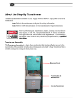
Figure 2. PM#−!))t − Transformer

LT‐PM3100-201
Issue 1 Print 2
7
Charles Industries, Ltd. All rights reserved. Printed in the United States of America.
INSTALLING THE PM#−!))t
The PM− consists of two transformer units, a control unit and a remote display panel. A second remote
display panel can be purchased to provide an additional power output monitoring location on-board the boat.
Choosing an Electrical Wiring Method
There are two wiring methods that are acceptable for installation of the PM− as an isolation transformer in
accordance with the American Boat and Yacht Council (ABYC) Alternating Current (AC) Electrical Systems on
Boats standard. See Figure 3 and Figure 4.
Note: Figure 3 and Figure 4 are reprinted with permission from the American Boat and Yacht Council (ABYC).
To obtain the complete standard referenced or any other standards contact the ABYC.
Wired as an Isolation Transformer
The difference between the two methods below is that in Method 2, a main shore power circuit breaker with
Ground Fault Protection (GFP) must be used instead of a conventional circuit breaker, and the shore grounding
conductor is not wired past the inlet of the boat. Method 1 is most commonly used.
Note: The following electrical diagrams do not illustrate complete systems. Refer to the appropriate ABYC text.
Isolation Transformer System with Single-Phase 240-Volt Input, 120/240-Volt Single-Phase Output with Boat Grounded Secondary. Shield
Grounded on Shore and Metal Case Grounded on Boat (Figure 3). The ungrounded shore current-carrying conductors are connected from the
power inlet to the primary winding of the isolation transformer through an overcurrent protection device which simultaneously opens both cur-
rent-carrying conductors. Do not connect the shore neutral. Fuses shall not be used in lieu of simultaneous trip devices.
240-Volt branch circuit breakers and switches simultaneously open all current-carrying conductors.
120-Volt branch circuit breakers are permitted to use single-pole breakers in the ungrounded current-carrying conductors.
Polarization of conductors must be observed in all circuits.
The green grounding wire from the shore is connected to the shore power inlet shell which is insulated from metal-hulled boats. Do not connect
the shore green wire to the boat ground.
The grounded neutral from the secondary of the isolation transformer and the case of the transformer are connected to the system ground,
neutral conductor and engine negative terminal or its bus.
Figure 3. Electrical Diagram − Method 1

LT-PM3100−201 Issue 1 Print 2
8 Charles Industries, Ltd. All rights reserved. Printed in the United States of America.
Isolation Transformer System with Single-Phase 240-Volt Input, 120/240-Volt Single-Phase Output, Ground Fault Protection and a Grounded
Secondary. Shield and Metal Case Grounded on Boat (Figure 4) − The ungrounded shore current-carrying conductors are connected from the
power inlet to the primary winding of the isolation transformer through a ground fault protection device which simultaneously opens both cur-
rent-carrying shore conductors. Fuses shall not be used in lieu of simultaneous trip devices.
240-Volt branch circuit breakers and switches simultaneously open all current-carrying conductors.
120-Volt branch circuit breakers are permitted to use single-pole breakers in the ungrounded current-carrying conductors.
Polarization of conductors must be observed in all circuits.
The green grounding wire from the shore power inlet is not connected to the isolation transformer shield or case nor to the boat ground.
Figure 4. Electrical Diagram − Method 2
Choosing a Mounting Location for the Transformers
When choosing a mounting location for the PM−, placement of the two transformers can be up to 50 feet
(15 meters) from the control unit, allowing for the equal weight distribution of the transformers to best balance the
boat. Consideration should also be made for a light audible hum that is present when the transformers are in op-
eration. It is best not to install the transformers adjacent to areas of the boat that are preferred to be kept quiet.
The transformers should be mounted horizontally. Special care should be taken to mount each of the transform-
ers on supports that can sustain a shock load of at least twice the weight of itself. Finally, transformers generate
heat during normal operation. Proper ventilation around the case is important. Allow for 4 inches (10 centime-
ters) of clearance on all sides of the unit and at least two inches between the back of the unit and the surface it is
mounted on.
Choosing a Mounting Location for the Control Unit
The control unit may be placed in a convenient location, not exceeding 50 feet (15 meters) from each of the
transformers. It too should be mounted horizontally. Inside the control unit are contactors that make a soft
“clanking” sound when the unit is in use. It may be preferable to not place the control unit in or near an area that
should be kept quiet. Special care should be taken to mount the control unit on supports that can sustain a shock
load of at least twice the weight of itself. The control unit will generate heat during normal operation. Proper ven-
tilation around the case is important. Allow for two inches (5 centimeters) of clearance on all sides of the unit.
Do not store equipment on or next to the PM#−!))t. The PM#−!))t transformers, in operation, can
reach high temperatures and must have free airflow to prevent overheating or possible damage to
adjacent materials.
WARNING − FIRE HAZARD

LT‐PM3100-201
Issue 1 Print 2
9
Charles Industries, Ltd. All rights reserved. Printed in the United States of America.
Choosing the Appropriate Wire Type and Gauge
All input conductors should be at least 4 AWG, and all output conductors should be at least 1/0 AWG, stranded,
600 volt rating, UL type AWM, UL 1426 equivalent or better. See ABYC standards for AC electrical systems on
boats for more details on conductor types and sizing.
Choosing Electrical Wiring
The PM− is intended to be used as an isolation transformer. In this application, there is no fault current
path for the wiring from the shore power inlet to the PM− output connections. For this reason, the wiring
should only be done with a jacketed cable (0.030 inches jacket thickness minimum) such as UL type 1426 boat
cable or by using a marine cable set wire (type SO or equivalent). This wiring should be installed in the boat in a
protected area and routed to avoid contact with sharp edges or hot surfaces.
Strain relief cord grip connectors or another method must be used to prevent wires from chafing on
the metal case and causing an electrical short. See installation instructions for suitable connector
kit. Use wire rated for at least 90 degrees Celsius, and sized on the basis of 75 degrees Celsius rated
wire amperage.
WARNING − ELECTRICAL SHOCK AND FIRE HAZARD
The PM− is intended for hard-wiring in a permanent location. Non-metallic strain relief/grip connectors (see
Table 1) are required, and included with the unit, to secure wires or cables going into or out of the PM−.
Table 1. Recommended Strain Relief Connectors and Accessories
Description* Manufacturer Catalog
Number Locknut Charles Number
Cord Range: 1.39 inches (35 millime-
ters)−1.69 inches (43 millimeters) Thomas & Betts 2707 145 18-900736-0
0.89 inches (23 millimeters) to 1.09 inches
(28 millimeters) Thomas & Betts 2702 144 25223
0.66 inches (17 millimeters) to 0.78 inches
(20 millimeters) Thomas & Betts 2675 142 18-900250-0
Strain Relief Kit − 4 AWG Wire Charles N/A Included 97−001121−A
Strain Relief Kit − 6 AWG Wire Charles N/A Included 97−001120−A
*All strain relief connectors must be of a non-metallic type to conform to UL requirements.
Overcurrent Protection
Overcurrent protection must be provided at the time of installation by a two-pole circuit breaker on each primary
supply (incoming shore power AC) and each secondary (boat system AC power) circuit. Each shore power AC
input breaker should be rated at 100 amps and each boat system AC output breaker should be rated at 200
amps.
To avoid serious injury or death from high voltage electrical shock disconnect AC shore power
before opening panel.
WARNING − HIGH VOLTAGE
While making connections to the PM− reference Figure 5.
The wiring installation will depend on the method chosen in the section titled Choosing an Electrical Wiring Meth-
od. Follow the procedure below to make the appropriate connections.

LT-PM3100−201 Issue 1 Print 2
10 Charles Industries, Ltd. All rights reserved. Printed in the United States of America.
Step Action
1. Remove the terminal access cover on the transformer.
2. Remove the front cover on the control unit.
3. Install the strain relief connectors.
4. Undo the chucks and compression grommets from the strain relief connectors.
5. Slide the strain relief connector chuck and compression grommets down and over the input and output
cables.
6. Strip back the insulating layers to the appropriate length.
7. Crimp ring terminals on all wires using the proper tool.
8. Connect all wiring as shown in Figure 5 and described in Table 2 through Table 4.
9. Re-assemble and tighten all strain relief connectors.
10. Re-install the terminal access cover.
Transformer
Transformer
Control Unit
Remote Display
Side 1
Side 2
Circuit Breaker
Circuit Breaker
Cat 5 Wire
50-foot Maximum
Side 1 Side 2
Output Output
{Side 1 Input
{Side 2 Input
*Heavy Cable
50-foot Maximum
BNC
50-foot Maximum
BNC
*Heavy Cable
{Cable/Wire included with the product
Customer provided
*Ring lugs on each end of the cable are
customer provided
See
Table 3
See
Table 3
See
Table 4
See
Table 4
(See Table 2)
(See Table 2)
Shore Cable − 4 AWG Minimum
Output − 1/0 AWG Minimum
Output − 1/0 AWG Minimum
Shore Cable − 4 AWG Minimum
Figure 5. Typical Wiring Connections

LT‐PM3100-201
Issue 1 Print 2
11
Charles Industries, Ltd. All rights reserved. Printed in the United States of America.
Table 2. PM#−!))t Connections from the Transformers to the Control Unit
Side Connection Wire
1 T1 Black
1 T2 Red
1 T3 Black with Red Stripe
1 T4 Red with Black Stripe
Case Ground Ground Green with Yellow Stripe
2 T1 Black
2 T2 Red
2 T3 Black with Red Stripe
2 T4 Red with Black Stripe
Table 3. Input Connections to the Transformers
Side Connection Wire
1 L1 Black
1 N Neutral
1 L2 Red
2 L1 Black
2 N Neutral
2 L2 Red
Table 4. Output Connections from the Control Unit
Side Connection Wire
1 L1 Black
1 N Neutral
1 L2 Red
2 L1 Black
2 N Neutral
2 L2 Red
Securing Covers
After all connections and terminations have been made, the terminal access cover on the transformer and the
front cover to the control unit should be re-installed using all hardware supplied.
Connect the BNC-BNC cables from the transformers to the control unit (see Figure 5).
Installing and Wiring the Remote Panel
The PM− remote panel provides a visual display of the operating modes of the unit without having to go
physically look at it. Up to two remote panels may be used with the PM−. Contact the Charles Marine &
Industrial Group for more information on obtaining a second display unit if desired.
Follow the procedure below to connect the remote panel to the PM−.

LT-PM3100−201 Issue 1 Print 2
12 Charles Industries, Ltd. All rights reserved. Printed in the United States of America.
Step Action
1. Using the template provided with the remote panel, carefully cut out the shaded portion in the de-
sired mounting location.
2. Using the template provided, drill 4 pilot holes for no.10 self-tapping screws.
3. Route the cable to the PM− control unit using care to avoid chafing and sharp bends.
4. Strip back approximately 1/2-inch (13mm) of the outer cable jacket (not the wires).
5. Insert the insulated conductors into the provided RJ45 plug assembly (see Figure 6) and crimp us-
ing the proper tool for CAT5 connectors.
6. Insert the RJ45 plug from step 5 into the socket marked “IN” on the rear of the display. The
PM− remote is provided with an additional socket “OUT” for the connection of a second dis-
play if desired.
7. Insert the pre-installed RJ45-plug, provided on the 50-foot Cat 5 cable, into the RJ45-socket lo-
cated on the right side of the PM− control unit.
Metal
Contacts (up)
RJ45 Plug
Cat 5 Cable
(50 feet provided −
cut to desired lengrth)
1 through 8 (see Wire Connection Chart) Wire Connection Chart
Contactor Color
1
2
3
4
5
6
7
8
Green/White
Green
Orange/White
Blue
Blue/White
Orange
Brown/White
Brown
Cable
Jacket
Wires
12345678
Figure 6. Remote Panel RJ45 Plug (Front View) with Wire Connection Chart
Applying Power
Power should only be applied after all connections and terminations have been made and the terminal access
cover is secure. Plug in the shore power AC and turn on the appropriate circuit breakers to apply power. Refer to
the section on Proper Operation.
OPERATING THE PM#−!))t
Proper Operation
The PM− is designed to operate in the best possible mode without any user intervention. The PM−
will select one of three possible modes of operation automatically: Normal, Separate or Single-Source (Shore
Cable 1 or Shore Cable 2). These modes of operation are described in Table 6 and more fully later in this docu-
ment. Diagrams of the operating modes are shown in Figure 7. Boosting is available in all except the Manual
Override mode and discussed later in this document.
Note: When operating in a single souce mode, the source selector switch must be in the position that corre-
sponds to the shore cable being used.

LT‐PM3100-201
Issue 1 Print 2
13
Charles Industries, Ltd. All rights reserved. Printed in the United States of America.
When power is first applied to Shore Cable 1 (assuming the PM− has been disconnected from the power
source at least 15 seconds), there will be no output on the PM−. The PM− will wait for approximate-
ly 25 seconds for a second shore cable to be connected. During this time, the PM− will display on the local
and remote (if connected) displays the voltage found on the shore cables as referenced in Table 5.
Table 5. Control Unit & Remote Display Examples at Initial Startup
Note: Typically the Remote Display shows the middle two lines of the Control Unit Display.
CONTROL UNIT MEANING
− Initial Startup −
Src 1: Found 234V
Src 2: Found 230V
↵= Setup
1. Initial startup indicator.
2. Shore cable 1 connected, the display indicates the input voltage.
3. Shore cable 2 connected, the display indicates the input voltage.
4. Pressing the RETURN key will force the system to enter the setup menu.
REMOTE DISPLAY
Src 1: Found 234V
Src 2: Found 230V
1. Shore cable 1 connected, the display indicates the input voltage.
2. Shore cable 2 connected, the display indicates the input voltage.
CONTROL UNIT MEANING
− Initial Startup −
Src 1: Found 234V
Src 2:
↵= Setup
1. Initial startup indicator.
2. Shore cable 1 connected, the display indicates the input voltage.
3. Shore cable 2 is not connected or below the minimum operating voltage.
4. Pressing the RETURN key will force the system to enter the setup menu.
REMOTE DISPLAY
Src 1: Found 234V
Src 2:
1. Shore cable 1 connected, the display indicates the input voltage.
2. Shore cable 2 is not connected or below the minimum operating voltage.
The system will begin to analyze power 25 seconds after the initial startup. If the voltage is above the minimum
required, the PM− will automatically select one of the three automatic modes.
Table 6. Modes of Operation
Mode Description
Normal This mode is available when the 2 shore power AC input cables (Shore Cable 1 and
Shore Cable 2) are connected, functioning and either 0 degrees (in-phase) or 180 de-
grees (out-of-phase) when compared to each other. The AC load is shared between the
2 shore cables. The total AC amperage is the sum of Shore Cable 1 and Shore Cable
2, up to 200 amps at 240 volts (48,000 VA). (Figure 7)
Note: The source selector switch, located in the manual override compartment, can
be set to either the “Source 1” or “Source 2” position.
Separate This mode is selected by the PM− when the 2 shore power AC cables (Shore
Cable 1 and Shore Cable 2) are connected, but phasing cannot be corrected by the
PM−. Shore Cable 1 and Shore Cable 2 remain isolated from each other and op-
erate independently. The total AC amperage is up to 100 amps at 240 volts (24,000
VA) for each output. (Figure 7)
Note: The source selector switch, located in the manual override compartment, can
be set to either the “Source 1” or “Source 2” position.

LT-PM3100−201 Issue 1 Print 2
14 Charles Industries, Ltd. All rights reserved. Printed in the United States of America.
Mode Description
Shore Cable 1 This mode is selected by the PM− when AC shore power is connected to Shore
Cable 1 only, and the source selector switch located in the manual override compart-
ment is set to the “Source 1” position. The total AC amperage of outputs 1 and 2 is 100
amps at 240 volts (24,000 VA). (Figure 7)
Note: When operating in Shore Cable 1 mode only, adding power to the second
shore cable will cause the unit to restart after a pre-set cycle, allowing the sys-
tem to switch into Normal or Separate mode if the power is stable.
Shore Cable 2 This mode is selected by the PM− when AC shore power is connected to Shore
Cable 2 only, and the source selector switch located in the manual override compart-
ment is set to the “Source 2” position. The total AC amperage of outputs 1 and 2 is 100
amps at 240 volts (24,000 VA). (Figure 7)
Note: When operating in Shore Cable 2 mode only, adding power to the first shore
cable will cause the unit to restart after a pre-set cycle, allowing the system to
switch into Normal or Separate mode if the power is stable.
Off Power is still being supplied to the PM−, but the outputs are turned off. This
mode is only available for doing maintenance on the PM−.
Isolation/
Boost
Shore Output A
Output BIsolation/
Boost
Isolation/
Boost Output A
Output BIsolation/
Boost
Normal Mode Separate Mode
Cable 1
Shore
Cable 2
Shore
Cable 1
Shore
Cable 2
Isolation/
Boost Output A
Output BIsolation/
Boost
Source 1 Mode
Shore
Cable 1
Shore
Cable 2
Isolation/
Boost Output A
Output BIsolation/
Boost
Source 2 Mode
Shore
Cable 1
Shore
Cable 2
Figure 7. Modes of Operation Diagram

LT‐PM3100-201
Issue 1 Print 2
15
Charles Industries, Ltd. All rights reserved. Printed in the United States of America.
EXPLANATION OF THE DISPLAY INFORMATION
In each of the modes of operation the PM− is continually monitoring the system. The modes of operation
are summarized in Table 6 and illustrated in Figure 7.
Note: The source selector switch, located in the manual override compartment, must be set to the mode that
corresponds to the desired mode of operation.
Normal Mode
When the PM− is operating in a Normal mode the control unit will display the output similar to the one
shown in Table 7. The Remote display will rotate the output between the first line and the middle two lines.
Table 7. Control Unit & Remote Display Output in Normal Mode
Note: The Remote Display unit alternates the display of information two lines at a time.
CONTROL UNIT MEANING
Mode: Normal 14696VA
1:208V 35A BOOST
2:206V 36A BOOST INV
↵= Setup
The system is running in Normal Mode. Output power is 14696 Volt−Amps.
Shore cable 1 input voltage is 208V. Current draw is 35 Amps. Output voltage
is boosted 15%.
Shore cable 2 input voltage is 206V. Current draw is 36 Amps. Output voltage
is boosted 15%. The input phase is 180 out of phase as compared to shore
cord 1.
Pressing the RETURN key will force the system to enter the setup menu.
Separate Mode
When the PM− is operating in a Separate mode the control unit will display the output similar to the one
shown in Table 8. The Remote display will rotate the output between the first line and the middle two lines.
Table 8. Control Unit & Remote Display Output in Separate Mode
Note: The Remote Display unit alternates the display of information two lines at a time.
CONTROL UNIT MEANING
Mode: Seprte 9540VA
1:240V 29A
2:215V 12A BOOST
↵= Setup
The system is running in Separate Mode. Both cables, but not power, are com-
bined. Output power is 9540 Volt-Amps.
Shore cable 1 input voltage is 240V. Current draw is 29 Amps.
Shore cable 2 input voltage is 215V. Current draw is 12 Amps. Output voltage
is boosted 15%.
Pressing the RETURN key will force the system to enter the setup menu.
If the PM− detects an incorrect shore power AC phase relationship, the PM− will not combine the
incoming shore power AC sources. The PM− outputs will be limited in amperes to their respective shore
power inputs. Separate Mode will continue until both shore power sources are disconnected. Once reconnected,
the PM− will attempt to restart following the standard startup sequence.
If the PM− has detected a fault on one side (example Shore Cable 1) it will disconnect the output power on
the side with the fault, wait for the source power to stabilize and restart the faulted side following a normal power
sequence for a single side. The user is notified of the problem.
Source 1 and Source 2 Modes
When the PM− is operating with a single shore cable, either Shore Cable 1 or Shore Cable 2, the control
unit will display the output similar to the one shown in Table 9. The Remote display will rotate the output between
the first line and the middle two lines.

LT-PM3100−201 Issue 1 Print 2
16 Charles Industries, Ltd. All rights reserved. Printed in the United States of America.
Table 9. Control Unit & Remote Display Output in Source 1 Mode
Note: The Remote Display unit alternates the display of information two lines at a time.
CONTROL UNIT MEANING
Mode: Src 1 22184VA
1:236V 94A
2:0V 0A NOT USED
HEAVY LOAD ↵= Setup
The system is running in Source 1 Mode. Single cable only. Output power is
22184 Volt-Amps.
Shore cable 1 input voltage is 236V. Current draw is 94 Amps.
Shore cable 2 input is not connected.
System warning about heavy load. Reduce load. Pressing the RETURN key
will force the system to enter the setup menu.
The system is operating on an incoming shore power supply. If an error occurs, the PM− will disconnect
the power and attempt a restart in approximately 45 seconds.
Should a second incoming shore supply be detected, the system will shut down and restart. Power will be inter-
rupted for a brief period of time during the restart. The system will analyze the shore supplies and switch to either
Normal or Separate mode as appropriate.
Off Mode (Only Available from the Setup Menu)
When the PM− is operating in an Off mode the control unit will display the output similar to the one shown
in Table 10. The Remote display will rotate the output between the first line and the middle two lines.
Table 10. Control Unit & Remote Display Output in Off Mode
Note: Typically the Remote Display shows the middle two lines of the Control Unit Display.
CONTROL UNIT MEANING
Mode: Off 0VA
1:212V 0A
2:219V 0A
↵= Setup
The system is turned off. There is no voltage on the output. Output power is 0.
Shore cable 1 input voltage is 212V. Current draw is 0 Amps.
Shore cable 2 input voltage is 219V. Current draw is 0 Amps.
Pressing the RETURN key will force the system to enter the setup menu.
Isolation
All modes listed in Table 6 have 4000 VRMS isolation from the source side to the output side.
Compatibility
The PM− will accept shore power AC input on either Shore Cable 1 or Shore Cable 2 within the following
range: Voltage: 185 to 260 Volts AC (recommended maximum)
Frequency: 50 Hz or 60 Hz
Shore power Load: 0 to 100 Amps per input (110 Amps maximum)
Thermal Protection
The PM− is equipped with a built-in thermal cutout that is embedded in the transformer windings. In the
event of sustained overload or overheating, this device will disable the transformer and shut down. When this oc-
curs all AC power being supplied from the transformer to the outputs will be disconnected and the manual over-
ride may not function. A red light on the transformer will indicate that the unit has been disabled due to overheat-
ing.
Reduce all AC loads and allow the unit to cool down. The thermal cutout will automatically reset and the
PM− will re-energize and resume normal operation.
Note: It may take a significant amount of time for the PM#−!))t to cool down depending on the ambient tem-
perature.

LT‐PM3100-201
Issue 1 Print 2
17
Charles Industries, Ltd. All rights reserved. Printed in the United States of America.
Voltage Boosting
All modes will automatically boost (with the exception of the Manual Override mode) the output voltage 15% over
the shore power AC voltage when it is less than optimal. This helps to prevent harm to voltage sensitive motors
and electronics on the boat. Voltage boosting is done automatically by the PM− and follows these simple
rules:
1. Upon power up, if the source voltage is less than 220 volts, the PM− will boost the output volt-
age by a factor of approximately 15% over the shore voltage.
2. If the shore voltage is or rises above 220 volts, the PM− will remove the boost and provide a
1:1 shore voltage to output voltage ratio.
3. Should the shore voltage drop below 210 volts, the PM− will again implement the boosting of
the output voltage by approximately 15% over the shore voltage.
Important notes about voltage boosting:
During voltage boosting, the usable current on the output side is reduced by 15% to prevent
overloading shore circuit breakers.
Shore Cable 1 voltage boosting is independent of Shore Cable 2 voltage boosting and vise versa.
When switching in and out of boost, the output voltage is not interrupted. However, the output voltage
may be reduced during the transition.
Input to output conversion is approximate. Due to varying loads, boost percentages vary slightly.
Power Interruptions and Recovery
The PM− is designed with a momentary power black-out detector. If a momentary loss of
power is detected by the PM− computer, the system will attempt a quick restart once the
power situation has passed. This feature minimizes the time the boat will experience a power loss
once the dock power has been restored.
If the power loss is greater than a few seconds, when the power returns, the system will restart using
the procedure described in section Proper Operation above.
Safety
The PM− will display three types of warnings on the remote display to indicate to the user that the limits of
the system are being reached. The warnings are below.
Low Voltage warning: When the input voltage on the shore cables falls below 200 volts, the system
will display a warning message on the remote display informing the user of low shore cable voltage.
The user should consider disconnecting the shore cables to prevent damage to motors and other
systems on the boat.
High Voltage warning: When the input voltage on the shore cables rises above 252 volts, the system
will display a warning message on the remote display informing the user of high shore cable voltage.
The user should consider disconnecting the shore cables to prevent damage to motors and other
systems on the boat.
High Current warning: When the current draw on a shore cable reaches 92 amps, the system will
display a warning message on the remote display informing the user of excessive current draw. The
user should immediately reduce the load on the system by turning off some electrical appliances or
systems to prevent a system shutdown if the current rises to the shutoff limit.
The PM− design is self-protecting and also protects the AC systems it powers. To do so, the PM−
has several safety features.

LT-PM3100−201 Issue 1 Print 2
18 Charles Industries, Ltd. All rights reserved. Printed in the United States of America.
Low Source Voltage: If the shore power AC input voltage drops below 185 volts, The PM− will
shut down. There is a built-in time delay to allow for large motor starting that may drag the voltage
below the threshold for a minimal period of time.
Over Load Condition: If the PM− detects an overload condition of 110% of the maximum
current draw of each input for an extended period of time, the system will shut down to protect the
system’s internal components. (i.e. 110 amps per shore cable or 220 amps total if both shore cables
are connected in Normal Mode)
Phasing: Normal Mode is only available when the Shore Cable 1 source and Shore Cable 2 source
are either 0 degrees or 180 degrees out of phase (typically, a source 180 degrees out of phase is due
to incorrect wiring on the shore). If the phasing of the source cannot be determined, or is not 0
degrees or 180 degrees out of phase, the PM− will revert to Separate Mode.
External AC Voltage on the outputs: If the PM− detects another AC power source (such as an
AC generator) on the outputs during startup, the PM− will not allow shore power AC to be
connected to the outputs until the external AC voltage source is removed from the outputs. This
feature prevents potential damage to AC systems on the boat (such as an AC generator).
Extreme Temperature: Should the PM− detect excess temperature internally (usually caused
by overloading), the PM− will immediately shutdown and the red LED, “Over Temperature”,
located on the transformers will turn on.
Integrated wire protection: If the wiring becomes shorted between the transformer and the control unit
the circuit breakers located in the affected transformers will trip.
Incorrect wiring: If the wiring between the transformer and the control unit is incorrect or missing, the
PM− will shut down and indicate the location of the fault when it attempts a system startup.
Isolation: 4000 VRMS isolation is designed to prevent a shock hazard from boat to shore.
Remote Display Warning Messages
Should any of the messages in Table 11 appear on the remote display, follow the suggested action and take pre-
caution to avoid a recurrence of the condition.
Table 11. Remote Display Warning Messages
REMOTE DISPLAY MEANING
Heavy Load WARNING
Reduce Load
1. The PM− is close to maximum power. Consider reducing the load.
Shore Cable WARNING!
Voltage very low!
1. Shore cable voltage is nearing the minimum voltage needed for PM−
to operate properly.
Shore Cable WARNING!
Voltage very high!
1. Shore cable voltage is nearing the recommended maximum voltage for
PM− . Consider switching the a generator to prevent damage to other AC
systems on the boat.
**** FAILURE ****
**** Detected ****
1. Indicates the PM− has stopped because of some reason. Often it’s
due to shore cable problems.
**** SYSTEM ****
**** HALTED ****
1. Indicates the PM− has been turned off. Usually this is due to a second
shore cable that has been detected.
2nd Cable Detected
Waiting for restart
1. Cable has been plugged in and the system has detected it.
2. Waiting for cable to stabilize before restarting.
System will attempt
a restart in 15 sec
1. System will restart in the displayed number of seconds.

LT‐PM3100-201
Issue 1 Print 2
19
Charles Industries, Ltd. All rights reserved. Printed in the United States of America.
If any of the fault conditions triggers the PM− to shutdown (other than over temperature), the local and re-
mote displays will describe the condition and the possible methods to remedy the problem. In addition, the sys-
tem will try to restart after approximately 45 seconds.
Manual Override
Manual override is for emergency situations only, and is not intended for normal use. When operating in manual
mode, the user should pay particular attention to the input voltage and load on the system as not to damage the
PM− or systems that rely on the PM− for power. Of particular concern is extremely low or high input
voltage which may damage devices in the boat.
Table 12. Manual Override Mode
Mode Description
Manual Override To be used when the PM− control unit has malfunctions or the operation of
the PM− is necessary when voltage is outside of the normal operating limits.
During the operation in manual override, isolation is maintained.
Note: Display voltage and boost not available.
Use the following procedure to enter the manual override mode.
Step Action
1. Disconnect all shore cables.
2. Remove the manual override access cover on the PM− control unit and switch the manual
override switch to ”override mode”.
3. Connect one or both of the shore cables to power. If connecting only a single cord, shore cable 1
must be connected to the power source. The system will operate as in SEPARATE mode described
earlier with the following exceptions:
a. The computer and all displays are disengaged and off.
b. Four LEDs located in the manual override switch compartment are off.
c. Boost is not available. The system only operates in non-boost mode.
d. All the computer controlled safety shutdown mechanisms are disabled
except over-temperature.
Use the following procedure to exit the manual override mode.
Step Action
1. Disconnect all shore cables.
2. Flip the manual override switch on the PM− control unit to automatic mode.
3. Replace the manual override access cover.
POST INSTALLATION VERIFICATION
Post installation verification should be done after installing the PM− and making all the final connections,
or after servicing the PM− to verify that the connections in the boat and to the control unit and transformers
are functioning properly.
Note: The remote display (and optional second display if present) should be installed prior to performing the
Post Installation Verification.
Voltage Boosting
During the testing sequence, depending on the shore power voltage, the PM− may automatically turn on
the voltage boost mechanism. If this occurs, there may be a momentary reduction in the power and the remote
display (if present) will indicate “BOOST” after the shore voltage. Likewise, if the voltage reaches a point where

LT-PM3100−201 Issue 1 Print 2
20 Charles Industries, Ltd. All rights reserved. Printed in the United States of America.
boost is not needed, there may be a momentary reduction in the power as it is removed. The post installation ver-
ification is not intended to verify voltage boosting, and therefore the voltage boost mechanism should be ignored.
The PM−’s voltage boosting function is set and pre-tested at the factory prior to shipment.
Phase Inverting
During testing, depending on the phase of the shore power, the PM− may invert the shore input that is 180
degrees out of phase. The remote display (if present) will show “INV”. The post installation verification is not in-
tended to verify phase correction, and therefore this should be ignored. The PM−’s phase inverting function
is set and pre-tested at the factory prior to shipment.
Digital Multi-Meters
Often a digital multi-meter will display stray voltage on a circuit that is open and not connected. The meter, be-
cause of its high input impedance, is actually detecting stray induced power on the open wire. This stray power is
not useable nor does it pose a danger to the user. However, this fact should be taken into consideration when
making measurements. Consult the user manual for the digital multi-meter to determine how to reduce
incorrect readings.
WARNING
It is possible to have back voltage on an unused shore cable if a wiring error has been made during
the installation of the PM#−!))t. Take appropriate precautions to prevent injury during the testing.
The Post Installation Verification procedure checks for wiring errors, removing any chance of back
voltage on an unused shore cable.
Testing Procedure
Before beginning the testing procedure the following should be readily available:
Volt Meter capable of measuring 120/240VAC
Estimated 15 minutes time to perform tests
Required Connections: Two 100-amp 240VAC shore power inputs with phasing that is 0 or 180
degrees apart. Do not test with shore power that has 120 degree phasing (split phasing off, a
three-phase connection is not acceptable.)
At least 12 amps of load is available to load the PM− down properly.
Follow the procedure below after the PM− is installed and wired, shore power is available, and when suffi-
cient wiring of the AC circuits on the boat are complete to provide at least 12 amps of load. (i.e. lighting, motors,
etc.).
Each mode of operation in this test procedure must be performed in the order shown, which are:
1. Source 1 Mode
2. Source 2 Mode
3. Normal Mode
4. Manual Override Mode
/