Page is loading ...

SERVICE MANUAL
Room Air Conditioner
MODEL : LS-P0760CL/P0760HL LS-P0820C
LS-P0960CL/P0960HL
LS-S0960CL/S0960HL LS-S1120C
LS-S1260CL/S1260HL
LS-S1420CL LS-S1421CL
CAUTION
BEFORE SERVICING THE UNIT, READ THE “SAFETY
PRECAUTIONS” IN THIS MANUAL.

Contents
Functions 3
Product Specifications (Cooling Only) 5
Product Specifications (Cooling & Heating) 7
Dimensions 8
Refrigeration Cycle Diagram 10
Wiring Diagram 11
Operation Details 13
Display Function 21
Self-Diagnosis Function 21
Installation 22
Operation 41
Disassembly of the parts (Indoor Unit) 43
2-way, 3-way Valve 46
Cycle Trouble Shooting Guide 53
Electronic Parts Trouble Shooting Guide 54
Electronic Control device 59
Schematic Diagram 63
Exploded View & Replacement Parts List 67
ƒ¡2ƒ¡

Functions
ƒU Room temperature sensor. (THERMISTOR)
ƒU Maintains the room temperature in accordance with the Setting Temp.
ƒU Indoor fan is delayed for 5 sec at the starting.
ƒU Restarting is inhibited for approx. 3 minutes.
ƒU High, Med, Low
--- Lights up in operation
--- Lights up in Sleep Mode
--- Lights up in Timer Mode
--- Lights up in Deice Mode (for Heating Model)
OUTDOOR --- Lights up in compressor operation (for Cooling Model)
ƒU Intermittent operation of fan at low speed.
ƒU The fan is switched to low(Cooling), med(Heating) speed.
ƒU The unit will be stopped after 1, 2, 3, 4, 5, 6, 7 hours.
ƒU The fan is switched to intermittent or irregular operation
ƒU
The fan speed is automatically switched from high to low speed.
ƒU The louver can be set at the desired position or swing
up and down automatically.
Indoor Unit
Operation ON/OFF by Remote controller
Sensing the Room Temperature
Room temperature control
Starting Current Control
Time Delay Safety Control
Indoor Fan Speed Control
Operation indication Lamps (LED)
Soft Dry Operation Mode
ƒU Both the indoor and outdoor fan
stops during deicing.
ƒU The indoor fan stops until the
evaporator piping temperature
will be reached at 28¡ .
Sleep Mode Auto Control
Natural Air Control by CHAOS Logic
Airflow Direction Control
ƒ¡3ƒ¡
Deice (defrost) control (Heating)
Hot-start Control (Heating)

ƒ¡4ƒ¡
Remote Controller
Operation ON/OFF
Reset
Operation Mode Selection
Fan Speed Selection
Room Temperature Display
Temperature Setting
Setting the Time or Time
Timer Selection
Timer Setting
Timer Cancel
Sleep Operation
Airflow Direction Control
(Cooling
model only)
(Heating
model only)
TEMPERATURE
LOW HIGH
(Low) (Med) (High) (CHAOS)
Cooling Operation Mode.( )
Soft Dry Operation Mode.( ) Auto Operation Mode.( )
Heating Operation Mode.( )
CHAO
S
ON
OFF
SET
CANCEL
Fan Operation Mode
RESET
: High:39°C LOW:11°C
: Cooling
Down to 20°C
Up to 30°C
: Heating
Down to 16°C
Up to 30°C
: OFF, ON, OFF ON
: Cancel Sleep Mode, Timer ON or Timer OFF.
: 1, 2, 3, 4, 5, 6, 7, Off Timer
: Cooling Model Only

ƒ¡5ƒ¡
Product Specifications (Cooling Only)
Model Name
Item Unit
Cooling Capacity BTU/h 7,200 7,300 8,400 8,500 8,800 9,000 12,000 12,000
Moisture Removal §⁄/h 1.0 1.2 1.2 1.2
Power Source §j, V, Hz 1§j220-240V, 50Hz
Indoor 4.6 5.3 7.3 8.9
Outdoor 25 25 25 25
Indoor 35 36 37 38 36 37 38
Outdoor 46 47 47 48 47 48 49
Input W 690 715 890 900 730 750 1,180 1,180
Running Current A 3.2 3.2 4.0 3.9 3.4 3.3 5.8 5.4
E.E.R. BTU/h-W 10.4 10.2 9.44 9.44 12.0 12.0 10.17 10.17
Indoor 8 8 10 15
Outdoor 25 25 25 25
Indoor 790¡¿230¡¿142 880¡¿302¡¿183
Outdoor 660¡¿540¡¿260
Indoor 7 7 9.5 9.5
Outdoor 29 29 29 30
Refrigerant (R-22) g 560 490 780 700
Airflow Direction Control (Up & Down) § § § §
Remocon Type L.C.D Wireless
Liquid 1/4" (6.35)
Gas 3/8" (9.52) 1/2"(12.7)
Sleeping Operation § § § §
Drain Hose § § § §
Connecting Cable 1.0mm
2
Power Cord 1.0mm
2
Air Circulation
Noise Level
m
3
/min
dB (A)¡ 3
Service Valve
Motor Output
Dimensions
(W¡¿H¡¿D)
Net. Weight
W
mm
kg
LS-P0760CL LS-P0960CL LS-S0960CL LS-S1260CL
SPEC. AT 220/240V

ƒ¡6ƒ¡
Model Name
Item Unit
Cooling Capacity BTU/h(kcal/h) 7,500(1,900) 11,000(2,772) 13,300(3,350) 14,000(3,550)
Moisture Removal §⁄/h 1.2 2.3 2.3 2.5
Power Source §j, V, Hz 1Ø, 220~V, 60Hz
Indoor 5.5 9.0 9.0 10.1
Outdoor 23 24 24 27
Indoor 36 39 39 39
Outdoor 47 49 49 50
Input W 710 1,050 1,378 1,500
Running Current A 3.3 4.9 6.3 6.9
E.E.R. BTU/h-W 10.6 10.5 9.7 9.3
Indoor 4.5 19.8 19.8 19.8
Outdoor 20 30 30 35
Indoor 790¡¿230¡¿142 880¡¿302¡¿183
Outdoor 660¡¿540¡¿260
Indoor 6 9.5 9.5 9.5
Outdoor 29 31.5 33.5 31.5
Refrigerant (R-22) g 600 710 980 750
Airflow Direction Control (Up & Down) § § § §
Remocon Type L.C.D Wireless
Liquid 1/4" (6.35)
Gas 3/8" (9.52) 1/2" (12.7)
Sleeping Operation §
Drain Hose §
Connecting Cable 1.0mm
2
Power Cord 1.0mm
2
Air Circulation
Noise Level
m
3
/min
dB (A)¡ 3
Service Valve
Motor Output
Dimensions
(W¡¿H¡¿D)
Net. Weight
W
mm
kg
LS-P0820CL LS-S1120CL LS-S1420CL LS-S1421CL
SPEC. AT 220V

ƒ¡7ƒ¡
Product Specifications (Cooling & Heating)
Model Name
Item Unit
Cooling 7,000 7,000 8,400 8,500 9,400 9,500 11,700 12,000
Heating 7,300 7,500 9,400 9,500 10,200 10,500 12,600 13,000
Moisture Removal §⁄/h 1.3 1.17 1.2 1.2
Power Source §j, V, Hz 1§j220-240V, 50Hz
Indoor 5.3 6.3 7.6 8.9
Outdoor 24 25 25 25
Indoor 36 38 36 37 37 38
Outdoor 47 49 47 48 48 49
Cooling 710 720 910 940 940 950 1,210 1,250
Heating 730 740 940 990 900 950 1,160 1,230
Cooling 3.1 4.5 4.5 6.4 6.2
Heating 3.3 4.5 4.5 6.2 6.0
E.E.R. Cooling BTU/h¡⁄w 9.86 9.7 9.23 9.0 10.0 10.0 9.7 9.6
C.O.P Heating W/W 2.93 2.97 2.93 2.81 3.32 3.2 3.2 3.1
Indoor 8 8 10 15
Outdoor 25 25 25 25
Indoor 790¡¿230¡¿142 880¡¿302¡¿183
Outdoor 660¡¿540¡¿260
Indoor 7 7 9.5 9.5
Outdoor 30 31 31 33
Refrigerant (R-22) g 600 540 1,020 1,150
Airflow Direction Control (Up & Down) § § § §
Remocon Type L.C.D Wireless
Liquid 1/4" (6.35)
Gas 3/8" (9.52) 1/2"(12.7)
Sleeping Operation § § § §
Drain Hose § § § §
Connecting Cable 1.0mm
2
Power Cord 1.0mm
2
Air Circulation
Noise Level
Input
Running
Current
Capacity BTU/h
Service Valve
Motor Output
Dimensions
(W¡¿H¡¿D)
Net. Weight
m
3
/min
dB (A)¡ 3
W
A
W
mm
kg
LS-P0760HL LS-P0960HL LS-S0960HL LS-S1260HL
SPEC. AT 220/240V

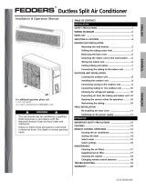
Dimensions
(1) Indoor Unit
ƒ¡8ƒ¡
W
D
H
Installation plate
45
70
Hole for piping
50
Tubing hole cover
Tubing hole cover
W
D
H
Installation plate
Hole for piping
Tubing hole cover
Tubing hole cover
20
50
MODEL
DIM
W mm 790 880
H mm 230 302
D mm 142 183
LS-P0760CL/P0760HL/P0820CL
LS-P0960CL/P0960HL
LS-S0960CL/S0960HL/S1120CL
LS-S1260CL/S1260HL/S1420CL/S1421CL
LS-P0760CL/P0760HL
LS-P0820CL
LS-P0960CL/P0960HL
LS-S0960CL/S0960HL
LS-S1120CL
LS-S1260CL/S1260HL
LS-S1420CL/S1421CL

(2) Outdoor Unit
W L2
L3
L1
D
H
L4
L5
Liquid side (2-way valve)
Gas side (3-way valve)
MODEL
DIM
W mm 660
H mm 540
D mm 260
L1 mm 297
L2 mm 66
L3 mm 447
L4 mm 17
L5 mm 82
LS-P0760CL/P0760HL, LS-P0820CL, LS-P0960CL/P0960HL
LS-S0960CL/S0960HL, LS-S1120CL, LS-S1260CL/S1260HL
LS-S1420CL, LS-S1421CL
ƒ¡9ƒ¡

Refrigeration Cycle Diagram
ƒ¡10ƒ¡
Pipe size(Diameter:§j)
MAX. Max
MODEL Piping length Elevation
Gas Liquid
(m) (m)
LS-P0760CL/P0760HL
LS-P0820CL 3/8" 1/4" 7 5
LS-P0960CL/P0960HL
LS-S0960CL/S0960HL
LS-S1120CL
LS-S1260CL/S1260HL
LS-S1420CL/S1421CL
INDOOR UNIT OUTDOOR UNIT
HEAT
EXCHANGE
(EVAPORATOR)
HEAT
EXCHANGE
(CONDENSOR)
COMPRESSOR
ACCUMU
LATOR
GAS SIDE
3-WAY VALVE
LIQUID SIDE
2-WAY VALVE
CAPILLARY TUBE
COOLING
HEATING
REVERSING
VALVE
(Heating Model Only)
1/2" 1/4" 7 5

Wiring Diagram
ƒ¡11ƒ¡
F
CH
BL
R S
C
COMP
FAN
MOTOR
BL
CAPACITOR
RD
TO INDOOR UNIT
OUTDOOR WIRING DIAGRAM
RD
BR
OLP
BR
YL
PILLAR
TERMINAL
BL
3854AR2262F
1(L) 2(N)
1
GN/YL
BL
BR
BLACK
GN/YL
BL
BR
F
CH
BL
R S
C
COMP
FAN
MOTOR
BL
CAPACITOR
RD
TO INDOOR UNIT
OUTDOOR WIRING DIAGRAM
RD
BR
OLP
YL
PILLAR
TERMINAL
BL
3854AR2262E
1(L) 2(N)
GN/YL
1
GN/YL
BL
BR
3 4
BK
BK
2
RD
BL
BR
REVERSING
VALVE
RD
BK
3
BR
BLACK GRAY
MODEL INDOOR UNIT OUTDOOR UNIT
LS-P0760CL
LS-P0820CL
LS-P0960CL
LS-S0960CL
LS-S1120CL
LS-S1260CL
LS-S1420CL
LS-S1421CL
LS-P0760HL
LS-P0960HL
LS-S0960HL
LS-S1260HL
¤Ø
¤Œ
¤º
¤
¤
¤Ł
¤ ¤Ł

ƒ¡12ƒ¡
BLACK
BL
BR
GN/YL
BR BL
GN/YL
GN/YL
POWER
BR BL
BL
OR
BR
YL
CN-FAN
SSR-L
SSR-M
SSR-H
CN-TRANS
CN-TH
CN-UP/DOWN
CN-DISP
THERMISTOR
MAIN PCB
ASM
DISPLAY PCB ASM
INDOOR WIRING DIAGRAM
3854AR2262D
GN/YL
TO OUTDOOR UNIT
PILLAR
TERMINAL
CN-4WAY
CN-POWER
RY-COMP
FUSE T2A
2
1
3
4
BR BL
TRANS
FORMER
FORCED
OPERATION
SWITCH
SH-CAPA
RD
MOTOR
1(L)
2(N)
STEP
MOTOR
RD
1(L) 2(N)
BLACK
BL
BR
GN/YL
BR BL
GN/YL
GN/YL
POWER
BR BL
BL
OR
BR
YL
RD
CN-FAN
SSR-L
SSR-M
SSR-H
SH-CAPA
AC PCB
ASM
CN-TRANS
CN-TH
CN-AC/DC
CN-UP/DOWN
CN-DISP
THERMISTOR
DC PCB
ASM
DISPLAY PCB ASM
INDOOR WIRING DIAGRAM
3854AR2262B
GN/YL
TO OUTDOOR UNIT
PILLAR
TERMINAL
RY-COMP
FUSE T2A
2
1
3
4
BR BL
TRANS
FORMER
FORCED
OPERATION
SWITCH
MOTOR
STEP
MOTOR
1(L)2(N)
1(L)
2(N)
¤Ø ¤Œ
BLACK
BL
BR
RD
BK
GN/YL
GRAY
BR BL
GN/YL
GN/YL
POWER
BR BL
BL
OR
BR
YL
CN-FAN
SSR-L
SSR-M
SSR-H
CN-TRANS
CN-TH
CN-UP/DOWN
CN-DISP
THERMISTOR
MAIN PCB
ASM
INDOOR WIRING DIAGRAM
3854AR2262C
GN/YL
BK RD
TO OUTDOOR UNIT
RY-FAN
PILLAR
TERMINAL
RY-4WAY
CN-4WAY
CN-POWER
RY-COMP
FUSE T2A
2
1
3
4
BR
BL
TRANS
FORMER
FORCED
OPERATION
SWITCH
SH-CAPA
RD
MOTOR
STEP
MOTOR
DISPLAY PCB ASM
RD
1(L) 2(L)
1(L)
2(N)
3 4
BLACK
BL
BR
RD
BK
GN/YL
GRAY
BR BL
GN/YL
GN/YL
POWER
BR BL
BL
OR
BR
YL
RD
CN-FAN
SSR-L
SSR-M
SSR-H
SH-CAPA
AC PCB
ASM
CN-TRANS
CN-TH
CN-AC/DC
CN-UP/DOWN
CN-DISP
THERMISTOR
DC PCB
ASM
DISPLAY PCB ASM
INDOOR WIRING DIAGRAM
3854AR2262A
GN/YL
TO OUTDOOR UNIT
RY-FAN
PILLAR
TERMINAL
RY-4WAY
CN-POWER
RY-COMP
FUSE T2A
2
1
3
4
BR BL
TRANS
FORMER
FORCED
OPERATION
SWITCH
MOTOR
STEP
MOTOR
BK RD
CN-4WAY
1(L) 2(L)
1(L)
2(N)
43
¤º ¤

Operation Details
(1) The function of main control
1. Time Delay Safety Control
ƒU3min¡ƒ The compressor is ceased for 3minutes to balance the pressure in the refrigeration cycle.
(Protection of compressor)
ƒU2sec¡ƒ The indoor fan is ceased for 2sec. to prevent relay noise.
(Protection of fan relay and micro chip)
ƒU30sec¡ƒThe 4-way valve is ceased for 30sec. to prevent the refrigerant-gas abnormal noise when the Heating
operation is OFF or switched to the other operation mode.
2. Airflow Direction Control
ƒU This function is to swing the louver up and down automatically and to set it at the desired position.
ƒU The procedure is as the following.
1st ; Press the ON/OFF Button to operate the product.
2nd ; Press the Airflow Direction Control Button to swing the louver up and down automatically.
3rd ; Repress the Airflow Direction Control Button to set the louver as the desired position.
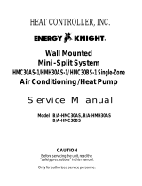
3. Cooling Mode Operation
ƒU When selecting the Cooling( ) Mode Operation, the unit will operate according to the setting by the remote
controller and the operation diagram is as following
4. Cooling or Heating Mode with Sleep Mode Auto Operation
ƒU When selecting the Cooling( ) or the Heating( ) combined with the Sleep Mode Auto Operation( ), the
operation diagram is as following.
ƒ¡13ƒ¡
Horizontal 0
1
2
3
4
5
6
7
8
Setting point:
Setting range for:
(Close)
7°
110°
Cooling
Approx. 28°
Heating
Approx. 28°
Cooling
Heating
Heating
Cooling
Horizontal 0
1
2
3
4
5
6
7
8
Setting point:
Setting range for:
(Close)
8°
150°
Cooling
Approx. 32°
Heating
Approx. 32°
Cooling
Heating
Heating
Cooling
LS-S0960CL/S0960HL, LS-S1120CL
LS-S1260CL/S1260HL
LS-S1420CL, LS-S1421CL
LS-P0760CL/P0760HL, LS-P0820CL
LS-P0960CL/P0960HL
Intake Air temp.
COMP. ON
(SET TEMP.+0.5¡ )
COMP. OFF
(SET TEMP. -0.5¡ ) More than More than
3 minutes 3 minutes
Selecting Selecting Selecting
fan speed fan speed fan speed
COMPRESSOR ON OFF ON OFF ON
INDOOR FAN Low Low
¢”
¢”

¡Æ Cooling Mode with the Sleep Mode
ƒU The setting temperature will be raised by 1¡ 30minutes later and by 2¡ 1 hour later.
ƒU The operation will be stopped after 1, 2, 3, 4, 5, 6, 7 hours.
¡Æ Heating Mode with the Sleep Mode.
ƒU The operation will be stopped after 1, 2, 3, 4, 5, 6, 7 hours.
ƒ¡14ƒ¡
Intake Air temp.
COMP. ON
(SET TEMP.+0.5¡ )
COMP. OFF
(SET TEMP. -0.5¡ ) Morethan More than
3 minutes 3 minutes
INDOOR FAN Low Low Low Low Low
COMPRESSOR ON OFF ON OFF ON
Delay 3 minutes
30 minutes 30 minutes
1¡
1¡
Setting Temp. +3¡
(Compressor OFF)
Setting Temp.
(Compressor ON)
Indoor Fan Med. Med. Med. Med. Med. Med.
Compressor ON OFF ON OFF ON OFF
¢”
¢”
¢”
¢”

5. Auto Operation
ƒU The operation procedure is as following.
ƒNIf initial mode is decided, that mode is continued without the room temperature changing.
ƒƒUU
Auto Operation for Cooling.
ƒ¡15ƒ¡
Press Start/Stop Button
Select Auto Operation Mode
Check the Room temperature
Operation mode
Indoor fan speed are automatically decided by Fuzzy rule.
Setting temperature
Intake-air
temperature
Operation Mode Heating Soft Dry Cooling
Operation Condition Intake-air Temperature Setting temperature Fan speed Air Direction Control
Over 26°C 25°C
Over 24°C~below 26°C Intake air -1.0°C
Over 22°C~below 24°C Intake air -0.5°C
Over 20°C~below 22°C Intake air temperature
below 20°C 20°C
Over 20°C~below 30°C Fuzzy control
below 20°C 20°C
Over 30°C 30°C
below 21¡
below
24¡
~
Over 24¡
Over
21¡
When Auto Operation
initial start
When Switch to
Auto Operation
Controlled
by Fuzzy logic
1/f rhythm
Intake-Air temp
Setting Temp. +0.5°C
(Compressor OFF)
Setting Temp.-0.5°C
(Compressor ON)
Indoor Fan
Compressor ON OFF ON OFF
Fuzzy Speed
¢”
¢”

ƒƒUU
Auto Operation for Soft Dry.
The Setting temperature will be set to the same that of the current intake-air temperature.
- Compressor ON temperature; Setting temperature +1°C
- Compressor OFF temperature; Setting temperature -0.5°C
ƒƒUU
Auto Operation for Heating.
ƒ¡16ƒ¡
Intake Air temp. below 20°C over 20°C~below 21°C
Setting temp. 20°C Intake air Temperature +0.5°C
21°C
20°C
20°C
Intake-Air temp.
Setting temp.
20.5°C
21°C

6. Natural Wind by CHAOS logic
There are common rules in the irregular changes amid the breeze of highlands and valleys, the sound of
streams, the songs of birds in the forest and brain waves of relaxation.
Mmm... the breath-taking and touchy feeling of wind from the deep mountains and dark valleys.
Through analysis in its chaos simulator, Goldstar has successfully created such a feeling of freshness and
serenity by analyzing the frequency of natural wind.
Generally natural wind has the following character (frequency-Magnitude), for example dark vally, sea, moun-
tain wind.
So as to make a similar Natural wind function, Indoor fan speed is shifted to high from low or reversely in
according to the CHAOS logic.
ƒ¡17ƒ¡
Magnitude
frequency(Hz)
natural wind function

7. Heating Mode Operation
The unit will operate according to the setting by the remote controller and the operation diagram is shown as
following.
8. Hot-Start Control
ƒU The indoor fan stops until the evaporator piping temperature will be reached at 28¡ . (BY TEMPERATURE)
ƒU The operation diagram is as following.
ƒ¡18ƒ¡
Intake Air temp.
Setting temp.+3¡
(Compressor OFF)
Setting temp.
(Compressor ON)
INDOOR FAN Low OFF Low Low OFF
COMPRESSOR ON OFF ON OFF
ƒU A point; The indoor pipe temperature to be 35°C
The indoor fan operates minimum 10sec. even if falls lower than 35°C
ƒU B point; The indoor pipe temperature to be 35°C
The indoor fan operates minimum 10sec. even if falls lower than 35°C
Selecting fan
speed
HOT
START
OFF
Selecting fan
speed
minimum
10sec.
A A
minimum
10sec.
minimum
10sec.
B
¢”
¢”
PIPING
TEMP 28°C
60 sec.
COMPRESSOR
INDOOR
FAN
LOWOFF
SELECTING
FAN SPEED
ON
(HOT-START BY TEMPERATURE)

9. Deice Control
ƒU Deicing operation is controlled by timer and sensing the indoor pipe temperature.
ƒU Deicing operation checks the indoor pipe temperature and Intake-air temperature at 25 minutes and 60 min-
utes on starting of heating operation, and discriminates by temperature difference.
ƒU When the heating operation passed 25 minutes, the temperature (¡ T1=TE1–TR1) is checked and memorized
with checking the indoor pipe temperture (TE1) and the indoor Intake-air temperature (TR1).
ƒU When the heating operation passed 60 minutes, deicing operation checks the indoor pipe temperature (TE2)
and the indoor Intake-air temperature (TR2), and checks the temperature difference (¡ T2=TE2–TR2) and the
temperature difference ¡ Td(=¡ T1–¡ T2) of ¡ T1, ¡ T2.
If the temperature difference (¡ Td) become more than the option temperature, deicing operation starts.
ƒU At that time, deicing operation time is decided.
ƒU The deicing operation time stops after deicing operation started.
ƒU If deicing operation start, above heating operation time is reset, so if deicing operation is finished, the heating
operation time is recounted.
ƒU The deicinig time and the operation diagram are as following.
ƒ¡19ƒ¡
60 minutes
Heating
25 MINS
Heating
TE1
TR1
TE2
TR2
TR1
TE1
Heating
25 MINS
Deicing
Pipe Temp.
Intake Air
Temp.
T1
T2
T1
TEMP °C
INDOOR FAN
OUTDOOR FAN
COMPRESSOR
4WAY VALVE
ON
ON
ON
ON
OFF
OFF
ON
OFF
ON After HOT-START finished
ON
ON
ON
Td (=T1– T2) Over 3.5°C 3.0~3.5°C 2.5~3.0°C 2.0~2.5°C below 2.0°C
Deicing Time 12mins 11mins 10mins 9mins Heating Operation

10. Soft Dry Operation.
ƒU During Soft Dry Operation, the compressor ON temperature is the setting temperature plus 1¡ , the compres-
sor OFF temperature is the setting temperature minus 0.5¡
ƒU When the room temperature rises over the compressor ON temperature, the operation mode is switched to the
cooling mode.
ƒU When the room temperature falls between the compressor ON temperature and OFF temperature, the opera-
tion mode is switched to the Soft Dry Operation.
In this temperature range, 10min. Dry Operation, 5.5min operation OFF, 1.5min. only fan operation repeat. Dur-
ing 10min Dry operation, even if the room temperature falls below compressor OFF temperature, 10min(MAX)
Compressor ON from starting of Dry operation which includes 4 min. Compressor ON operation below the
comperssor OFF temperature.
ƒU In micom dehumidify mode, control of fan speed is as following.
11. Forced operation
ƒU If you lose wireless remote controller, you can operate the unit with forced operation switch.
ƒU The standand conditions are as following.
ƒ¡20ƒ¡
ROOM TEMP.
SETTING TEMP.+1°C
(COMP. ON)
SETTING TEMP.
(COMP. OFF)
INDOOR FAN OFF
LOW
LOW OFF LOW LOW
COMPRESSOR ON OFF ON OFF ON
Selecting
fan speed
2 minutes
5.5 minutes
maximum
4 minutes
1 minutes
1.5 minutes
10 minutes
maximum
10minutes
Operation
Cooling
Dry operation
Heat pump Model
Room Temp¡ˆ 24°C 21°C ¡´Room Temp£…24°C Room Temp £…21°C
Operation Mode Cooling Cooling Soft Dry Heating
FAN Speed High High Low High
Setting Temp. 24°C 24°C Room Temp. 22°C
Cooling Model
¢”
¢”
/