Page is loading ...

INSTALLATION INSTRUCTIONS
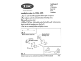
Max Load Capacity: 20kg(44lbs)
20kg
(44lbs)
MAX
Pitching angle:
-15° ~ +15°
Pivot: 360°
Swivel: 180°
M
LCD Wall Mount
7
Maintenance
Once you have mounted the bracket and the flat screen, check that they are sufficiently secure and safe to
use. You should check whether screws are fixed well each two months. If you have any doubts regarding the
installation, please consult our retailer or service department for detail.
Pitching angle adjustment
The pitching angle can be adjusted between -15°~15°, swivel: 180°, pivot: 360°, as shown in fig. 5.1.
5
360°
180°
180°
180°
fig.5.1
fig. 4.1
LOCK
The padlock
is not
included.
-15°
+15°
• Place the adapter bracket mounted display onto the plate of Articulated Arm Assembly, as shown in fig 4.1.
• Tighten the safety screws through the mounting holes till the display can be fixed, do not over tighten! As
shown in fig 4.1.
Important: Make sure the brackets mounted display is correctly mounted and the safety locking screws are
locked safely before loosening the display.
4
Installing the Display

NOTE: Read entire instruction sheet before you start installtion and assembly.
WARNING
• Do not begin to installation of the product on you have read and understand the
instructions and warnings contained in this Installation Sheet. If you have any question
regarding any of the instruction or warning, Please contact your local distributor.
• Please refer to manufacturer’s installation guide recommendation for required
distance from wall to avoid risk of property damage.
• This product should only be installed by someone of good mechanical aptitude, with
experience and basic building, and fully understands.
• Make sure that the supporting surface will safely support the combined load of the
equipment and all attached hardware and components.
• Never exceed the Maximum Load Capacity.
• If mounting to wood wall studs, make sure that mounting screws are anchored into
the center of the studs. Use of an “edge to edge” stud finder is highly recommended.
• Always use an assistant or mechanical lifting equipment to safely lift and position
equipment.
• Tighten screws firmly, but do not over tighten. Over tightening can damage the items,
greatly reducing their holding power.
• This product intended for indoor use only. Using this product outdoors could lead to
product failure and personal injury.
21
Component Checklist
IMPORTANT: Ensure you have received all parts against the component checklist prior to installing. If any parts
are missing or faulty, telephone the special franchiser for a replacement.
Package M
Package W
Tools required
Phillips Head Screw driver(200mm length exclude the handle)
Electric drill and 8mm masonry bit for concrete wall installation
Marking Pen
Hammer
·
·
·
·
ST5.5x50 (x3)
W-A
lag bolt
concrete anchor
W-B
(x3)
M4x14
M-A
(x4) M5x10 (x8)
M-B
D4 ( 4.5x )
washer (x4)
M-F
ø ø9
D (ø .5xø )
washer (x4)
M-G
5 5 12
M5x14 (x4)
M-C
D6 (ø6.6xø )
washer (x4)
M-H
12
M8x15 (x4)
M-E
adapter arm
C
(x4)
articulated arm
assembly (x1)
A
adapter bracket
B
(x1)
M6x14 (x4)
M-D
ø13.5xø5.5x3.2 (x4)
M-I

43
recommended. Based on their edges, draw a vertical line down the stud’s center.
• Place wall plate on wall as a template. And mark the center of the three mounting holes. Make sure that
the mounting holes are on the stud centerline.
• Drill three 1/8” (3mm) dia. Holes 1.2” (30mm) deep. Make sure that the wall plate is level, secure it using
three wood screws (W-A) as shown in fig. 1.1.
• Use a stud finder to locate the edges of the studs. Use of an edge-to-edge stud finder is highly
WOOD STUD WALL MOUNTING:
1a
WARNING
• Make sure that the supporting surface will safely support the combined load of the
equipment and all attached hardware and components.
• Tighten wood screws firmly, but do not over tighten. Over tightening can damage
the screws, greatly reducing their holding power.
• Make sure that mounting screws are anchored into the center of the studs. Use of
an “edge to edge” stud finder is highly recommended.
• Hardware provided is for attachment of mount through standard thickness drywall
or plaster into studs. Installers are responsible to provide hardware for other types
of mounting situations.
WARNING
• When installing wall mounts on cinder block, verify that you have a minimum of
1-3/8” of actual concrete thickness in the hole to be used for the concrete anchors.
Do not drill into mortar joints! Be sure to mount in a solid part of the block,
generally 1” minimum from the side of the block. It is suggested electric drill on
slow setting is used to drill the hole instead of a hammer drill to avoid breaking out
the back of the hole when entering a void or cavity.
• Installer must verify that the supporting surface will safely support the combined
load of the equipment and all attached hardware and components.
fig. 1.2
SOLID BRICK AND CONCRETE BLOCK MOUNTING:
1b
• Pre-drill these holes with a 8mm masonry bit to at least 50mm in depth. Insert a Concrete Anchor (W-B)
into each of these holes. Attach the Wall Plate to the wall using three wood screws (W-A), as shown in fig.1.3.
• Use the Wall Plate as a template to mark three holes locations on the wall, as shown in fig.1.2.
Stud
fig. 1.3
fig. 1.1
W-A
W-A
W-B

65
• To prevent scratching the screen, set a cloth on a flat, level surface that will support the weight of the screen.
• Place screen face side down. Place the adapter bracket on the back of screen, align to holes, as shown in fig.3.1
• Attach the adapter bracket to the back of the screen using appropriate combination of screws. as shown in fig.3.2,
fig.3.3, fig.3.4, fig.3.5, fig.3.6, fig.3.7, fig.3.8 and fig.3.9.
Installing Adapter Bracket
3
fig. 3.1
For VESA 200x200 compliant For VESA 200x100 compliant
2a,For VESA 200X200
place the four adapter arms on the adapter bracket and align to mounting holes. Using eight appropriate combination
of screws, and then tighten screws, Do not over tighten! as shown in fig.2.1
Assembling Adapter Arms
2
fig. 2.1
200
200
2b,For VESA 200X100
place the four adapter arms on the adapter bracket and align to mounting holes. Using four appropriate
combination of screws, adjust the level of adapter arms, and then tighten screws ,Do not over tighten!
as shown in fig.2.2
fig. 2.2
100
200
fig. 3.5fig. 3.4
M-B
Unit: mm
Unit: mm
M-B
For VESA 75x75 100x100 compliant
fig. 3.3
M-H
M-D
M-D
M-H
fig. 3.7fig. 3.6
M-A
M-C
M-F
M-G
M-I
M-A
M-C
M-F
M-G
M-I
fig. 3.9fig. 3.8
M-E
M-E
M-A
M-F
fig. 3.2
M-C
/