Miller NA214031D Owner's manual

Category
Welding System
Type
Owner's manual

This manual is also suitable for

The Miller NA214031D MigMatic Cooler is designed to provide cooling for Miller welding power sources. It features a compact design for easy installation and portability. The cooler has a built-in pump that circulates coolant through the power source to remove heat. The coolant is then returned to the cooler, where it is cooled by a fan and recirculated. The cooler also has a built-in thermostat that maintains the coolant at a consistent temperature. This helps to protect the power source from overheating and ensures optimal performance.

The Miller NA214031D MigMatic Cooler is designed to provide cooling for Miller welding power sources. It features a compact design for easy installation and portability. The cooler has a built-in pump that circulates coolant through the power source to remove heat. The coolant is then returned to the cooler, where it is cooled by a fan and recirculated. The cooler also has a built-in thermostat that maintains the coolant at a consistent temperature. This helps to protect the power source from overheating and ensures optimal performance.

OWNER’S MANUAL
MigMatic Cooler
Processes
Description
MIG (GMAW) Welding
OM-287469A 2020-05
CE
For product information,
Owner’s Manual translations,
and more, visit
www.MillerWelds.com
Thank you and congratulations on choosing Miller. Now you can get the
job done and get it done right. We know you don’t have time to do it any
other way.
That’s why when Niels Miller first started building arc welders in 1929,
he made sure his products offered long-lasting value and superior quality.
Like you, his customers couldn’t afford anything less. Miller products had
to be more than the best they could be. They had to be the best you could
buy.
Today, the people that build and sell Miller products continue the
tradition. They’re just as committed to providing equipment and service
that meets the high standards of quality and value established in 1929.
This Owners Manual is designed to help you get the most out of your
Miller products. Please take time to read the Safety Precautions. They
will help you protect yourself against potential hazards on the worksite.
We’ve made installation and operation quick and easy. With Miller, you
can count on years of reliable service with proper maintenance. And if for
some reason the unit needs repair, there’s a Troubleshooting section that
will help you figure out what the problem is, and our extensive service
network is there to help fix the problem. Warranty and maintenance
information for your particular model are also provided.
Miller Electric manufactures a full line of
welders and welding-related equipment. For
information on other quality Miller products, contact your local Miller
distributor to receive the latest full line catalog or individual catalog sheets.
Working as hard as you do
every power source from
Miller is backed by the most
hassle-free warranty in the
business.
From Miller to You
Milan_Thank
202001
TABLE OF CONTENTS
SECTION 1 SAFETY PRECAUTIONS - READ BEFORE USING 1.................................
1-1. Symbol Usage 1.......................................................................
1-2. Cooling Equipment Hazards 1............................................................
1-3. Additional Hazards For Installation, Operation, And Maintenance 1.............................
1-4. California Proposition 65 Warnings 2......................................................
1-5. Principal Safety Standards 2.............................................................
SECTION 2 DEFINITIONS 3..................................................................
2-1. Additional Safety Symbols And Definitions 3................................................
2-2. Miscellaneous Symbols And Definitions 4..................................................
SECTION 3 SPECIFICATIONS 5..............................................................
3-1. Serial Number And Rating Label Location 5................................................
3-2. Specifications 5........................................................................
3-3. Coolant Specifications 5................................................................
3-4. Environmental Specifications 5...........................................................
SECTION 4 INSTALLATION 6................................................................
4-1. Tipping 6.............................................................................
4-2. Selecting a Location 6..................................................................
4-3. Installing Cooler On MigMatic Welding Power Source 7......................................
4-4. Cooler Connections 8...................................................................
4-5. 7-Pin Rear Cable Cord Plug Information 8..................................................
4-6. 4-Pin Rear Cable Cord Plug Information 8..................................................
SECTION 5 OPERATION 9...................................................................
5-1. Front Panel Controls 9..................................................................
5-2. Rear Panel Controls 9..................................................................
SECTION 6 MAINTENANCE & TROUBLESHOOTING 10.........................................
6-1. Routine Maintenance 10.................................................................
6-2. T
roubleshooting
10......................................................................
SECTION 7 ELECTRICAL DIAGRAM 11........................................................
SECTION 8 PARTS LIST 12...................................................................
WARRANTY
OM-287469 Page 1
SECTION 1 SAFETY PRECAUTIONS - READ BEFORE USING
coolers 2020-02
7
Protect yourself and others from injury — read, follow, and save these important safety precautions and operating instructions.
1-1. Symbol Usage
DANGER! Indicates a hazardous situation which, if
not avoided, will result in death or serious injury. The
possible hazards are shown in the adjoining symbols
or explained in the text.
Indicates a hazardous situation which, if not avoided,
could result in death or serious injury. The possible
hazards are shown in the adjoining symbols or ex-
plained in the text.
NOTICE Indicates statements not related to personal injury.
Indicates special instructions.
This group of symbols means Warning! Watch Out! ELECTRIC
SHOCK, MOVING PARTS, and HOT PARTS hazards. Consult sym-
bols and related instructions below for necessary actions to avoid
these hazards.
1-2. Cooling Equipment Hazards
The symbols shown below are used throughout this manual
to call attention to and identify possible hazards. When you
see the symbol, watch out, and follow the related instructions
to avoid the hazard. The safety information given below is
only a summary of the more complete safety information
found in the Principal Safety Standards listed in Section 1-5.
Read and follow all Safety Standards.
Only qualified persons should install, operate, maintain, and
repair this equipment. A qualified person is defined as one
who, by possession of a recognized degree, certificate, or
professional standing, or who by extensive knowledge, train-
ing and experience, has successfully demonstrated the
ability to solve or resolve problems relating to the subject
matter, the work, or the project and has received safety train-
ing to recognize and avoid the hazards involved.
During operation, keep everybody, especially children, away.
HOT PARTS can burn.
Do not touch hot parts bare handed.
Allow cooling period before working on
equipment.
To handle hot parts, use proper tools and/or wear heavy, insu-
lated welding gloves and clothing to prevent burns.
FLYING METAL or DIRT can injure eyes.
Wear approved safety glasses with side
shields even under your welding helmet.
Touching live electrical parts can cause fatal shocks
or severe burns. The input power circuit and machine
internal circuits are also live when power is on.
Incorrectly installed or improperly grounded equip-
ment is a hazard.
ELECTRIC SHOCK can kill.
Do not touch live electrical parts.
Disconnect input power or stop engine before installing or
servicing this equipment. Lockout/tagout input power according to
OSHA 29 CFR 1910.147 (see Safety Standards).
Properly install, ground, and operate this equipment according to
its Owners Manual and national, state, and local codes.
Always verify the supply ground check and be sure that input
power cord ground wire is properly connected to ground terminal in
disconnect box or that cord plug is connected to a properly
grounded receptacle outlet.
Keep cords dry, free of oil and grease, and protected from hot metal
and sparks.
Frequently inspect input power cord and ground conductor for
damage or bare wiring – replace immediately if damaged – bare
wiring can kill.
Turn off all equipment when not in use.
Use only well-maintained equipment. Repair or replace damaged
parts at once. Maintain unit according to manual.
Keep all panels and covers securely in place.
1-3. Additional Hazards For Installation, Operation, And Maintenance
FALLING EQUIPMENT can injure.
Use correct procedures and equipment of ade-
quate capacity to lift and support unit.
If using lift forks to move unit, be sure forks are
long enough to extend beyond opposite side of
unit.
Keep equipment (cables and cords) away from moving vehicles
when working from an aerial location.
Follow the guidelines in the Applications Manual for the Revised
NIOSH Lifting Equation (Publication No. 94110) when manu-
ally lifting heavy parts or equipment.
OVERUSE can cause OVERHEATING
Allow cooling period; follow rated duty cycle.
Do not block or filter airflow to unit.
OM-287469 Page 2
READ INSTRUCTIONS.
Read and follow all labels and the Owners
Manual carefully before installing, operating, or
servicing unit. Read the safety information at
the beginning of the manual and in each
section.
Use only genuine replacement parts from the manufacturer.
Perform installation, maintenance, and service according to the
Owner’s Manuals, industry standards, and national, state, and
local codes.
Read and understand the Safety Data Sheets (SDSs) and the
manufacturers instructions for adhesives, coatings, cleaners,
consumables, coolants, degreasers, fluxes, and metals.
STEAM AND HOT COOLANT can burn.
Hose may rupture if coolant overheats.
Visually inspect condition of hoses before each
use. Do not use damaged hoses.
Allow cooling period before working on equipment.
HIGH PRESSURE FLUIDS can injure or kill.
Coolant can be under high pressure.
Release pressure before working on cooler.
If ANY fluid is injected into the skin or body seek medical help
immediately
.
MOVING PARTS can injure.
Keep away from moving parts such as fans.
Keep all doors, panels, covers, and guards
closed and securely in place.
Have only qualified persons remove doors, panels, covers, or
guards for maintenance and troubleshooting as necessary.
Reinstall doors, panels, covers, or guards when maintenance is
finished and before reconnecting input power.
1-4. California Proposition 65 Warnings
WARNING: This product can expose you to chemicals in-
cluding lead, which are known to the state of California to
cause cancer and birth defects or other reproductive
harm.
For more information, go to www.P65W
arnings.ca.gov
.
1-5. Principal Safety Standards
Safety in Welding, Cutting, and Allied Processes, American Welding
Society standard ANSI Standard Z49.1. Website: www.aws.org.
Safe Practices for the Preparation of Containers and Piping for Welding
and Cutting, American Welding Society Standard AWS F4.1 from Glob-
al Engineering Documents. Website: www
.global.ihs.com.
Safe Practices for Welding and Cutting Containers that have Held Com-
bustibles, American Welding Society Standard AWS A6.0 from Global
Engineering Documents. Website: www.global.ihs.com.
National Electrical Code, NFPA Standard 70 from National Fire Protection
Association. Website: www.nfpa.org and www. sparky.org.
Safe Handling of Compressed Gases in Cylinders, CGA Pamphlet P-1
from Compressed Gas Association. Website:www.cganet.com.
Safety in Welding, Cutting, and Allied Processes, CSA Standard
W117.2 from Canadian Standards Association.
Website: www.csagroup.org.
Safe Practice For Occupational And Educational Eye And Face Protec-
tion, ANSI Standard Z87.1 from American National Standards Institute.
Website: www.ansi.org.
Standard for Fire Prevention During Welding, Cutting, and Other Hot
Work, NFPA Standard 51B from National Fire Protection Association.
Website: www.nfpa.org.
OSHA Occupational Safety and Health Standards for General Industry,
Title 29, Code of Federal Regulations (CFR), Part 1910.177 Subpart N, Part
1910 Subpart Q, and Part 1926, Subpart J. Website: www.osha.gov.
OSHA Important Note Regarding the ACGIH TLV, Policy Statement on
the Uses of TLVs and BEIs. Website: www.osha.gov.
Applications Manual for the Revised NIOSH Lifting Equation from the
National Institute for Occupational Safety and Health (NIOSH). Web-
site: www.cdc.gov/NIOSH.
OM-287469 Page 3
SECTION 2 DEFINITIONS
2-1. Additional Safety Symbols And Definitions
Some symbols are found only on CE products.
Warning! Watch Out! There are possible hazards as shown by the symbols.
Safe1 201205
Do not discard product (where applicable) with general waste.
Reuse or recycle Waste Electrical and Electronic Equipment (WEEE) by disposing at a designated collection
facility.
Contact your local recycling office or your local distributor for further information.
Safe37 201704
Disconnect input plug or power before working on machine.
Safe5 201704
Do not remove or paint over (cover) the label.
Safe20 201704
Recycle.
Safe103 201209
XXXXX
Use coolant suggested by the manufacturer.
Safe52 201205
Please drain fluid according to instructions.
201205
Read the labels on the welding power source, wire feeder, or other
major equipment for welding safety information.
Safe71 201206
Read the Owners Manual before working on this machine.
Safe70 201206
OM-287469 Page 4
Safe50 201205
Plugged filter or hoses can cause overheating to the power source
and torch.
100 h. Std.
Safe51 201205
Every 100 hours, check and clean filter and check condition of hoses.
2-2. Miscellaneous Symbols And Definitions
A
Amperage
Alternating
Current
Voltage Input
Circulating Unit
With Coolant
Pump
V
Voltage
Water (Coolant)
Input
Disturbance
Read Operator’s
Manual
Suitable for
Welding in an
Environment with
Increased Risk of
Electric Shock
Water (Coolant)
Output
Line Connection
Protective Earth
(Ground)
IP
Degree Of
Protection
I
1
Primary Current
Remote
Hz
Hertz
On
Off
U
1
Primary Voltage
Single Phase
Cooling
OM-287469 Page 5
SECTION 3 SPECIFICATIONS
3-1. Serial Number And Rating Label Location
The serial number and rating information for this product is located on the back panel. Use rating label to determine input power requirements and/or
rated output. For future reference, write serial number in space provided on cover of this manual.
3-2. Specifications*
Model
Coolant
Tank
Capacity
Maximum
Cooling
Capacity
Input
Power
Cooler on Standby Cooler Enabled
Dimensions
Weight
MigMatic
Cool
2-1/2 gal
(5 L)
1000 Watts
(3412 BTU/hr)
1 qt/min
(1.0L/min)
400 VAC
50/60 Hz
Volts in: 400 VAC
I in: 54mA
Input power(W): 6
Input power(VA): 22
Volts in: 400 VAC
I in: 683mA
Input power(W): 237
Input power(VA): 273
L: 11-3/8 in. (720 mm)
H: 11-1/2 in. (292 mm)
W: 12 in. (305 mm)
Net: 50 lb
(23 kg)
Ship: 25 lb
(55 kg)
*IEC Cooling Capacity States That The Water Inlet Temperature Can Not Exceed 40° C Above Ambient Temperature At A 1l/ Min Flow Rate.
Recirculating Coolant System For Water-Cooled GTAW Torches And GMAW Guns.
Use With Guns/Torches Rated Up To 600 Amperes
3-3. Coolant Specifications
Do not use conductive coolant.
Application Coolant
GTAW Or Where High Frequency Current Is Used Coolant 050024004
Low Conductivity Coolant 043810*
Distilled Or Deionized Water Okay Above 32°F (0°C)
GMAW Or Where High Frequency Current Is Not Used Coolant 050024004
Low Conductivity Coolant 043810*
Aluminum Protecting Coolant 043809*
Distilled Or Deionized Water Okay Above 32°F (0°C)
Where Coolant Contacts Aluminum Parts Aluminum Protecting Coolant 043809*
*Coolants 043810 and 043809 protect to -37°F (-38°C) and resist algae growth.
NOTICE Use of any coolant other than those listed in the table voids the warranty on any parts that come in contact with the coolant (pump, radiator,
etc.).
3-4. Environmental Specifications
A. IP Rating
IP Rating
IP23S
This equipment is designed for outdoor use. It may be stored, but is not intended to be used for welding outside during precipitation unless
sheltered.
IP23S 201406
B. Information On Electromagnetic Compatibility (EMC)
! This Class A equipment is not intended for use in residential locations where the electrical power is provided by the public low
voltage supply system. There can be potential difficulties in ensuring electromagnetic compatibility in those locations, due to con-
ducted as well as radiated disturbances.
This equipment complies with IEC 61000-3-11 and IEC 61000-3-12.
ce-emc 4 2014-07
C. Temperature Specifications
Operating Temperature Range Storage/Transportation Temperature Range
14 to 104 °F (10 to 40°C)
68 to 77 °F (20 to 25°C)
Temp1_016- 08
The correction factor on the cooling power at an ambient temperature of 1045F (405C) is 0.625.
OM-287469 Page 6
SECTION 4 INSTALLATION
4-1. Tipping
! Do not move or operate
unit where it could tip.
Loc_cooler
2016-08
4-2. Selecting a Location
Position unit so air can circulate.
956172376_1-A
18 in.
(460 mm)
18 in.
(460 mm)
18 in.
(460 mm)
OM-287469 Page 7
4-3. Installing Cooler On MigMatic Welding Power Source
956172376_2-A
! Turn Off welding power source.
! Disconnect input power before in-
stalling cooler on welding power
source.
1 Welding Power Source
2 Cooler
3 Screws
Place power source on cooler and secure
with screws.
Tools Needed:
m30 Torx
1
2
3
OM-287469 Page 8
4-4. Cooler Connections
1 400 volt, 1 Amp AC Receptacle
2 400 volts AC Cord
Provides 115 VAC to power cooler.
3 7-Pin Receptacle (See Section 4-5)
Provides the following signals:
Signal to activate the cooler
Check for the presence of coolant flow
Check the presence of the cooler.
95617374-6-A
3
1
2
4-5. 7-Pin Rear Cable Cord Plug Information
956172374_1-A
7-Pin
Pin Pin Information
AWC CONTRO
L
1 Common
2 Automatic Water Cooler Control
3 Not Used
4 Automatic Water Cooler Protection
5 Common
6 Not Used
7 (GND) Not Used
4-6. 4-Pin Rear Cable Cord Plug Information
956172374_1-A
4-Pin
Pin Pin Information
AWC SUPPLY
1
Power Supply 400 volts AC
3 Power Supply 400 volts AC
2 Not Used
4 Earth Lead
OM-287469 Page 9
SECTION 5 OPERATION
5-1. Front Panel Controls
1 Power Switch S1
2 Pump Priming Push Button
3 Input Power Line 2A Fuse
4 Water Flow Alarm Indicator
Light
5 Cooler Operation Indicator
Light
6 Input Line Voltage
7 Water In Quick Connect
8 Water Out Quick Connect
Ref. 956172376_3-A
1 2345678
5-2. Rear Panel Controls
1 Tank Filler Neck
2 4-Pin Input Line Power Supply Cord
(see Section 4-5)
3 7-Pin Automatic Water Cooler
(A.W.C.) Cord (see Section 4-6)
4 Coolant Level Indicator
Ref. 956172376_3-A
1
2
3
4
OM-287469 Page 10
SECTION 6 MAINTENANCE & TROUBLESHOOTING
6-1. Routine Maintenance
! Disconnect power
before maintaining.
= Check = Change = Clean = Replace
* To be done by Factory Authorized Service Agent
Reference
Every
3
Months
NOTICE Clean coolant filter. Severe condi-
tions may require more frequent cleaning (con-
tinuous use, high/low temperatures, dirty envi-
ronment, etc.). Failure to properly clean cool-
ant filter voids pump warranty.
Coolant Filter
Every
6
Months
Cracked Parts Change Coolant (If Using
Water)
Replace Unreadable Labels
Every
12
Months
Change Coolant (If Using (B)050024004)
6-2. Troubleshooting
Trouble Remedy
Coolant system does not work. Be sure cooler input power and communication cables from power source are connected to cooler
receptacles.
Check input power line fuses or circuit breaker, and replace or reset if necessary.
Have Factory Authorized Service Agent check motor.
Decreased or no coolant flow. Add coolant.
Check for clogged hoses or coolant filter. Clean filter or clean / replace hoses if necessary.
Disconnect pump, and check for sheared coupling. Replace coupling if necessary.
OM-287469 Page 11
SECTION 7 ELECTRICAL DIAGRAM
Ref. 956172383-A
OM-287469 Page12
SECTION 8 PARTS LIST
Hardware is common and
not available unless listed.
956172376_4-A
16
15
20
21
13
12
11
10
13
14
22
9
19
18
17
1
23
24
25
8
5
6
3
4
2
26
27
7
Figure 8-1. Main Assembly, MigMatic Cool
OM-287469 Page13
Description
Part
No.
Dia.
Mkgs.
Item
No.
Figure 8-1. Main Assembly, MigMatic Cool
1 116170004 Grid, Front 2... ........... .. .....................................................
2 356029273 Nameplate, Front 1... ........... .. ................................................
3 556049428 Quick Coupling, Red 1... ........... .. .............................................
4 556049429 Quick Coupling, Blue 1... ........... .. ............................................
5 056067294 Switch, Pressure 1... ........... .. ................................................
6 556049430 Tee-Piece Water Connection 1... ........... .. ......................................
7 156122103 Panel, Side RH 1... ........... .. .................................................
8 T1 058021177 Transformer, Auxiliary 1... .... ... .. ............................................
9 156006105 Base 1... ........... .. ..........................................................
10 6506089039 Strain Relief 2... .......... .. ....................................................
11 057014434 Plug And Cable, AWC Control 1... ........... .. .....................................
12 057014435 Plug And Cable, Power 1... ........... .. ..........................................
13 027042004 Tank, Assembly 1... ........... .. .................................................
14 156005235 Tank, Support 1... ........... .. ...................................................
15 156121051 Cover 1... ........... .. ..........................................................
16 156122103 Panel, Side LH 1... ........... .. ..................................................
17 116117088 Deflector, Metal 4... ........... .. .................................................
18 056082111 Radiator 2... ........... .. ........................................................
19 FM 056126092 Motor, Fan 1... ... ... .. .....................................................
20 M 057011039 Motor And Pump 1... .... .... .. ................................................
21 156005236 Support, Pump 1... ........... .. ..................................................
22 156005237 Support 1... ........... .. ........................................................
23 PC1 057084243 Circuit Board, AWC Control 2... ... ... .. .......................................
24 S1 056067296 Switch, Power 1... .... ... .. ..................................................
25 056020081 Knob, Power Switch 1... ........... .. .............................................
26 056092104 Holder, Fuse 1... ........... .. ....................................................
26A F1 056092103 Fuse, 2A 1.. ... ... .. .......................................................
27 PRS 056093026 Switch, Push Button 1... ... ... .. .............................................
+When ordering a component originally displaying a precautionary label, the label should also be ordered.
To maintain the factory original performance of your equipment, use only Manufacturers Suggested
Replacement Parts. Model and serial number required when ordering parts from your local distributor.
OM-287469 Page 14
Notes
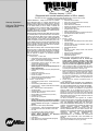
Effective January 1, 2020
(Equipment with a serial number preface of NA or newer)
This limited warranty supersedes all previous Miller warranties and is exclusive with no other
guarantees or warranties expressed or implied.
LIMITED WARRANTY Subject to the terms and conditions
below, Miller Electric Mfg. LLC, Appleton, Wisconsin and ITW
Welding (hereafter referred to as Miller) warrant to authorized
distributors that new Miller equipment sold after the effective date
of this limited warranty is free of defects in material and
workmanship at the time it is shipped by Miller. THIS WARRANTY
IS EXPRESSLY IN LIEU OF ALL OTHER WARRANTIES,
EXPRESS OR IMPLIED, INCLUDING THE WARRANTIES OF
MERCHANTABILITY AND FITNESS.
Within the warranty periods listed below, Miller will repair or replace
any warranted parts or components that fail due to such defects in
material or workmanship. Miller must be notified in writing within
thirty (30) days of such defect or failure, at which time Miller will
provide instructions on the warranty claim procedures to be
followed. Notifications submitted as online warranty claims must
provide detailed descriptions of the fault and troubleshooting steps
taken to diagnose failed parts. Warranty claims that lack the
required information as defined in the Miller Service Operation
Guide (SOG) may be denied by Miller.
Miller shall honor warranty claims on warranted equipment listed
below in the event of a defect within the warranty coverage time
periods listed below. Warranty time periods start on the delivery
date of the equipment to the end-user purchaser, or 18 months
after the equipment is shipped to an International distributor,
whichever occurs first.
1. 5 Years Parts — 3 Years Labor
* Original Main Power Rectifiers Only to Include SCRs,
Diodes, and Discrete Rectifier Modules
2. 3 Years — Parts and Labor Unless Specified
* Auto-Darkening Helmet Lenses (No Labor) (See
Classic Series Exception Below)
* Engine Driven W
elder/Generators
(NOTE: Engines are Warranted Separately by the
Engine Manufacturer.)
* Insight Welding Intelligence Products (Except External
Sensors)
* Inverter Power Sources
* Plasma Arc Cutting Power Sources
* Process Controllers
* Semi-Automatic and Automatic Wire Feeders
* Transformer/Rectifier Power Sources
3. 2 Years — Parts and Labor
* Auto-Darkening Helmet Lenses – Classic Series Only
(No Labor)
* Auto-Darkening Weld Masks (No Labor)
* Fume Extractors Capture 5, Filtair 400 and Industrial
Collector Series
4. 1 Year — Parts and Labor Unless Specified
* ArcReach Heater
* AugmentedArc and LiveArc Welding Systems
* Automatic Motion Devices
* Bernard BTB Air-Cooled MIG Guns (No Labor)
* CoolBelt (No Labor)
* Desiccant Air Dryer System
* Field Options
(NOTE: Field options are covered for the remaining
warranty period of the product they are installed in,
or for a minimum of one year — whichever is
greater.)
* RFCS Foot Controls (Except RFCS-RJ45)
* Fume Extractors Filtair 130, MWX and SWX Series,
ZoneFlow Extraction Arms and Motor Control Box
* HF Units
* ICE/XT Plasma Cutting Torches (No Labor)
* Induction Heating Power Sources, Coolers
(NOTE: Digital Recorders are Warranted
Separately by the Manufacturer.)
* Load Banks
* Motor-Driven Guns (except Spoolmate Spoolguns)
* PAPR Blower Unit (No Labor)
* Positioners and Controllers
* Racks (For Housing Multiple Power Sources)
* Running Gear/Trailers
* Subarc Wire Drive Assemblies
* Supplied Air Respirator (SAR) Boxes and Panels
* TIG Torches (No Labor)
* Tregaskiss Guns (No Labor)
* Water Cooling Systems
* Wireless Remote Foot/Hand Controls and Receivers
* Work Stations/Weld Tables (No Labor)
5. 6 Months — Parts
* Batteries
6. 90 Days — Parts
* Accessories (Kits)
* ArcReach Heater Quick Wrap and Air Cooled Cables
* Canvas Covers
* Induction Heating Coils and Blankets, Cables, and
Non-Electronic Controls
* MDX Series MIG Guns
* M-Guns
* MIG Guns, Subarc (SAW) Torches, and External
Cladding Heads
* Remote Controls and RFCS-RJ45
* Replacement Parts (No labor)
* Spoolmate Spoolguns
Miller’s True Blue® Limited Warranty shall not apply to:
1. Consumable components; such as contact tips,
cutting nozzles, contactors, brushes, relays, work
station table tops and welding curtains, or parts that
fail due to normal wear. (Exception: brushes and
relays are covered on all engine-driven products.)
2. Items furnished by Miller, but manufactured by others,
such as engines or trade accessories. These items are
covered by the manufacturers warranty, if any.
3. Equipment that has been modified by any party other than
Miller, or equipment that has been improperly installed,
improperly operated or misused based upon industry
standards, or equipment which has not had reasonable
and necessary maintenance, or equipment which has
been used for operation outside of the specifications for
the equipment.
4. Defects caused by accident, unauthorized repair, or
improper testing.
MILLER PRODUCTS ARE INTENDED FOR COMMERCIAL
AND INDUSTRIAL USERS TRAINED AND EXPERIENCED IN
THE USE AND MAINTENANCE OF WELDING EQUIPMENT.
The exclusive remedies for warranty claims are, at Miller’s
option, either: (1) repair; or (2) replacement; or, if approved in
writing by Miller, (3) the pre-approved cost of repair or
replacement at an authorized Miller service station; or (4)
payment of or credit for the purchase price (less reasonable
depreciation based upon use). Products may not be returned
without Miller’s written approval. Return shipment shall be at
customer’s risk and expense.
The above remedies are F.O.B. Appleton, WI, or Miller’s
authorized service facility. Transportation and freight are the
customer’s responsibility. TO THE EXTENT PERMITTED BY
LAW, THE REMEDIES HEREIN ARE THE SOLE AND
EXCLUSIVE REMEDIES REGARDLESS OF THE LEGAL
THEORY. IN NO EVENT SHALL MILLER BE LIABLE FOR
DIRECT, INDIRECT, SPECIAL, INCIDENTAL OR
CONSEQUENTIAL DAMAGES (INCLUDING LOSS OF
PROFIT) REGARDLESS OF THE LEGAL THEORY. ANY
WARRANTY NOT PROVIDED HEREIN AND ANY IMPLIED
WARRANTY, GUARANTY, OR REPRESENTATION,
INCLUDING ANY IMPLIED WARRANTY OF
MERCHANTABILITY OR FITNESS FOR PARTICULAR
PURPOSE, ARE EXCLUDED AND DISCLAIMED BY
MILLER.
This Limited Warranty provides specific legal rights, and other
rights may be available, but may vary by country.
Warranty Questions?
Call your ITW Welding
Regional Office.
mil int warr 2020-01
ORIGINAL INSTRUCTIONS PRINTED IN USA © 2020 Miller Electric Mfg. LLC 202001
ITW Welding Products B.V.
Edisonstraat 10 3261 LD
Oud-Beijerland (NL)
Phone: +31 (0) 186 641 444
Fax: +31 (0) 186 640 880
Model Name Serial/Style Number
Purchase Date (Date which equipment was delivered to original customer.)
Distributor
Address
Country Zip/Postal Code
Please complete and retain with your personal records.
Owner’s Record
Always provide Model Name and Serial/Style Number.
Contact a DISTRIBUTOR or SERVICE AGENCY near you.
Welding Supplies and Consumables
Options and Accessories
Service and Repair
Replacement Parts
Owner’s Manuals
Contact the Delivering Carrier to:
For Service
File a claim for loss or damage during
shipment.
For assistance in filing or settling claims, contact
your distributor and/or equipment manufacturer’s
Transportation Department.
Contact your Distributor for:
  • Page 1 1
  • Page 2 2
  • Page 3 3
  • Page 4 4
  • Page 5 5
  • Page 6 6
  • Page 7 7
  • Page 8 8
  • Page 9 9
  • Page 10 10
  • Page 11 11
  • Page 12 12
  • Page 13 13
  • Page 14 14
  • Page 15 15
  • Page 16 16
  • Page 17 17
  • Page 18 18
  • Page 19 19
  • Page 20 20

Miller NA214031D Owner's manual

Category
Welding System
Type
Owner's manual
This manual is also suitable for

The Miller NA214031D MigMatic Cooler is designed to provide cooling for Miller welding power sources. It features a compact design for easy installation and portability. The cooler has a built-in pump that circulates coolant through the power source to remove heat. The coolant is then returned to the cooler, where it is cooled by a fan and recirculated. The cooler also has a built-in thermostat that maintains the coolant at a consistent temperature. This helps to protect the power source from overheating and ensures optimal performance.

Ask a question and I''ll find the answer in the document

Finding information in a document is now easier with AI