Genie CM7600 Owner's manual

Category
Garage Door Opener
Type
Owner's manual
Check your ceiling where the power
head of your new unit will be mounted.
Plan how you wilt be mounting the power head.
It is possible that ceiling joists may not be in the
exact position needed with respect to the garage
door operator. It may be necessary to add an
additional bracket and fasteners (not included
with your new door operator kit).
Check the wall directly above the garage
door. The door operator's header bracket
must be securely fastened to this watt. Ensure
that the structure wilt provide a strong mounting
location.
Check to see if the mounting location
for the Safe-T-Beam ® System (STB) is
clear from obstruction and has a wood
surface available for attaching the STB brack-
ets. The brackets may be attached to concrete if
necessary but extra tools and special fasteners
(not supplied) will be required.
b_O'l" : 1-12 STB b_'_ck_:;£sd_;U_t_'s _;
You need a 110-120 Volt power supply
available. The outlet should be no more than
3 feet from the power head once it is mounted. (The
cord is 4 ft. in length.) SEE WARNING BELOW.
To avoid damage to your door and/or
operator, make sure you disable any door
locks prior to installing your operator.
Ensure that your door is properly balanced
and moving freely. SEE WARNING BELOW.
(NOT SHOWN) If your garage does not have
a separate entry door, you should consider
an emergency release kit (GER-2) for installation
on your garage door. See page C at the center of
this manual.
Is your garage door made of
light-weight steel, aluminum, fiberglass
or glass panels? Additional support bracing
must be added to these type doors. If this is the
case, please contact the door distributor or
manufacturer so that they can furnish you with a
"bracing kit."
, omeLink® is a universal
transceiver (a combined
transmitter and receiver), that provides a
convenient way to replace up to three hand-held
radio-frequency (RF) transmitters used to
activate devices such as gate operators, garage
door openers, entry door locks, security systems
and even home lighting. Additional HomeLink ®
information can be found at: www.homelink.com
or by calling 1.800.355.3515.
TYPICAL SECTIONAL DOOR iNSTALLATION
SUPPORT
BRACKET
ADDED
HEADER BRACKET
MOUNTING BOARD
BRACES
36" POWER CORD
TO
120V GROUNDED
OUTLET
EXTENSION SPRING
OR
TORSION SPRING
SAFE=T-BEAM®
II
Safe-T=Beam ® (STB} Non-Contact Reversing System
Step ladder
5/32" Drill Bit
Ratchet
©
7/16" and 9/16" Sockets
I {:D I[Z31@ I_1 (:_) I_DI O II
Carpenter's level
Adjustable wrench
Pencil
Wire strippers
Phillips screwdriver
Tape measure
Places an invisible beam across door opening that reverses the door during down travel to the fully open
position if anything passes through beam.
Safe-T=Reverse ® Contact Reversing System
Automatically stops and reverses a closing door within 2 seconds of contact with an object.
Safe-T=Stop ® Timed Reversed System
Automatically opens a closing door, if door does not close within 30 seconds.
Force Guard ® Control
Used to set the force required for opening and closing door. For maximum safety, set the minimum force
required to fully open and close door.
Automatic Lighting System
Two light bulbs up to 60 Watts max. each are used for safer entries and exits. The light turns on when door is
activated and automatically turns off 4.5 minutes later.
Manual Emergency Release
Allows the garage door to be opened or closed manually for emergencies or maintenance.
[1]P0werHeadAssemb,y
Item PartName Item PartName
1 Power Head Assembly M Terminal Strip
A Cover (By Series/Model) N No. 8-32 x 1/2" Hex Washer Head Screw
B Front Plate Assembly P No. 8-32 x 3/8" Slot Hex Washer Head Screw
C Light Socket R Capacitor Isolator
U Motor Harts 45 Bumper
E Receiver Assembly 4 1/4-20 Shoulder Bolt
F Capacitor (By Series/Model) 5 1/4" Flange Nut
G Opto Wheel 39 Coupler
H Opto-Luctor Assembly 41 No. 8-32 x 3/8" Phillips Hex Head Screw
J Sequencer Assembly 42 No. 8-32 x 3/8" Phillips Pan Head Screw
K Circuit Board Bracket 48 Mounting Straps
L Transformer 49 Light Lens
INTELLICODE ® Access Security System
Improves security of door operator by continuously changing the access code each time the remote control is
used. The door operator responds to each new code only once. An access code copied from a working system
and tried again will not control the door operator.
INTELLICODE ® l-Button Remote Control
Controls door operator by allowing the garage door to be opened and closed remotely.
INTELLICODE ® Multi-Button Remote Control
Operates multiple tntellicode ® equipped door operators.
Lighted Wall Button (some models)
Operates door operator from inside garage. DO NOT use with lighted wall console.
Wall Console (some models)
Works like a lighted wall button but includes a Vacation Lock Switch that disables all controls. LED indicator
shows whether system is powered, locked or unlocked. Makes console easy to find in dark. Controls door
opener from inside garage. Independent light control allows convenient manual control of the Automatic Lighting
System. DO NOT use with lighted wall button.
2]1-PieceRail& ScrewAssembly
,.,,, =.., =.., ,s*, Ii]I;,IIQIIII!CI....... = = ....... ........ ...........
Item
1
2
3
3A
3B
3C
4
5
6
7
8
9
10
11
12
13
15A
Part Name Item
3-Piece
PowerHeadAssembly(Seepage5) 1 1 15B
RailAssembly(1 piece) 1 16
RailAssembly(3 piece) 1 17
FirstRailSection 1 18
MiddleRailSection 1 19
End RailSection 1 20
1/4-20 HexHdShoulderBolt 2 2 21
1/4"-20 HexFlangeNut 2 2 22
CarriageStop 1 1 23
RailClamps 4 24
5/16" HexShoulderBolt 8 25
5/16" HexFlangeNut 5 13 26
CarriageAssembly 1 1 27
Collar 2 28
RetainingClip 2 29
RailStrap 1 1 30
OpenLimit SwitchAssembly (Grey) 1 1 31
PartName
3-Piece
CloseLimit Switch Assembly(Brown) 1 1
No.8-32x 3/8" HexHeadScrew 2 2
EmergencyReleaseCord 1 1
EmergencyReleaseKnob 1 1
EmergencyReleaseTag 1 1
HeaderBracket 1 1
DoorBracket 1 1
1/4"x2" LagScrew 8 8
Straight DoorArm 1 1
ClevisPin 2 2
Cotter Pin 2 2
CurvedDoorArm 1 1
3/8" x7/8" HexHeadBolt 2 2
3/8" HexFlangeNut 2 2
Wire _95ft =95ft
InsulatedStaple =30 _30
Wall Button varies varies
3]3-PieceRail&ScrewAssembly
8 _i ....... s.... w::; 8_;, >O>@Yd
Item
33
34
35
36
37
38
39
40
41
42
43
44
45
46
47
48
49
50
Part Name
WallConsole
#6 x1-1/4" PanHeadScrew
EntrapmentWARNINGLabel
Safe-T-Beam(STB)SystemSensor (GreenLED)
Safe-T-Beam(STB)SystemSource (RedLED)
Safe-T-Beam(STB)System Bracket
Coupler
No. 10x 11/4" Phillips HexHeadScrew
#8 x3/8" HexHeadScrew
#8 x3/8" PanHeadScrew
Safety& MaintenanceGuide
Wire Clip
Bumper
5/16"x 3/4"Hex HeadBolt
1/4-20x 3/4" Self-tappingScrew
MountingStraps
Light Lens (Shownon page5)
RemoteControl
varies
2
1
1
1
2
1
4
4
2
1
4
1
5
3
1
varies
3-Piece
varies
2
1
1
1
2
1
4
4
2
1
4
1
5
3
2
1
varies
U
@
@
®
@
remotes
vary
by model
@
_m
..... _ .i}:..//,ii
.... y
FASTENERS = Shown full size. See Parts List for description.
D
.J l
q--
1/4" Shoulder bolt w/flange
1/4" x 2" Lag screw Coupler
©
1/4" Flange nut
Carriage stop (net to scale)
8/16" Shoulder bolt w/flange
g (8)
5/16" Flange nut
tn
@
Collar
Clevis pin
Cotter pin
,21
3/8" Hex head bolt
3/8" Nut_
Insulated staple
#10 x 1-1/4" PhilHps hex head screw
N
#8 x3/8" Hex flange head screw
N
N
#8 x 3/8" Pan head screw
Wire clip
Rubber bumper
Clip
NI Nt
5/16" x 3/4" Hex head bolt
#8-32 x 3/8" Hex head screw
#6 x 1-1/4" Pan head screw
j_
1/4"-20 Self-drilling screw
OVERVIEW OF
POTENTIAL HAZARDS
Garage doors are large, heavy objects that move with the help of springs
under high tension and electric motors. Since moving objects, springs under
tension, and electric motors can cause injuries, your safety and the safety of
others depend on you reading the information in this manual, if you have
questions or do not understand the information presented, call your nearest
service representative.
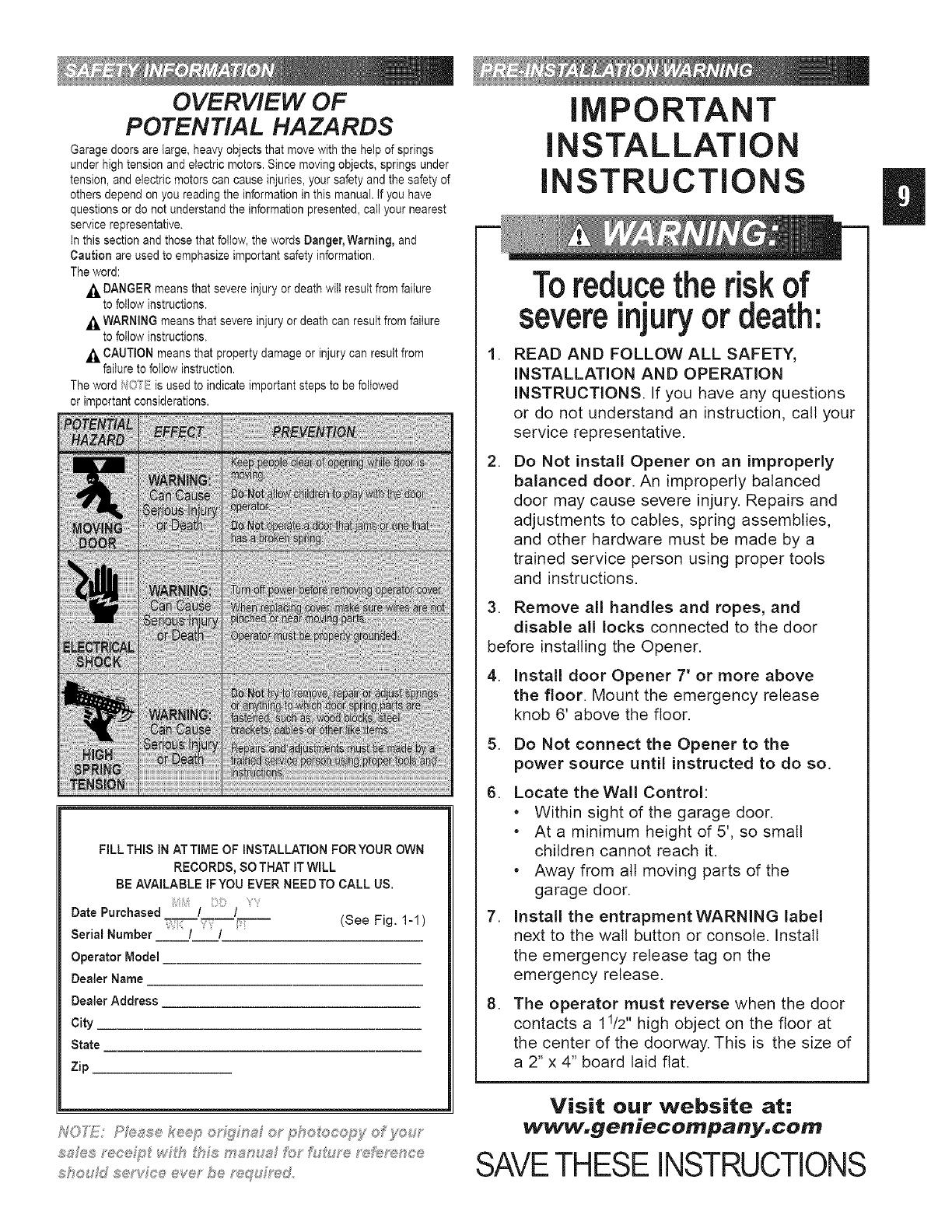
in this section and those that foilow, the words Danger, Warning, and
Caution are used to emphasize important safety information.
The word:
,_ DANGER means that severe injury or death wilt result from failure
to follow instructions.
,_ WARNING means that severe injury or death can result from failure
to follow instructions.
,_ CAUTION means that property damage or injury can result from
failure to foliow instruction.
The word f40*__:is used to indicate important steps to be followed
or important considerations.
FILL THISIN ATTIMEOF INSTALLATIONFORYOUROWN
RECORDS,SOTHATITWILL
BE AVAILABLE IFYOU EVERNEEDTOCALL US.
Date Purchased / /
Serial Number / / (See Fig. 1-1)
Operator Model
DealerName
DealerAddress
City
State
Zip
S'_ou d se vFo@eve" be ,u,_dr_,d
IMPORTANT
INSTALLATION
INSTRUCTIONS
,
,
Toreducethe risk of
severeinjuryordeath:
READ AND FOLLOW ALL SAFETY,
INSTALLATION AND OPERATION
INSTRUCTIONS. If you have any questions
or do not understand an instruction, call your
service representative.
Do Not install Opener on an improperly
balanced door. An improperly balanced
door may cause severe injury. Repairs and
adjustments to cables, spring assemblies,
and other hardware must be made by a
trained service person using proper tools
and instructions.
3. Remove all handles and ropes, and
disable all locks connected to the door
before installing the Opener.
4. Install door Opener 7' or more above
the floor. Mount the emergency release
knob 6' above the floor.
5. Do Not connect the Opener to the
power source until instructed to do so.
6. Locate theWall Control:
* Within sight of the garage door.
* At a minimum height of 5', so small
children cannot reach it.
* Away from all moving parts of the
garage door.
7. Install the entrapment WARNING label
next to the wall button or console. Install
the emergency release tag on the
emergency release.
8. The operator must reverse when the door
contacts a 11/2" high object on the floor at
the center of the doorway. This is the size of
a 2" x 4" board laid flat.
Visit our website at:
www.geniecompany.com
SAVETHESEINSTRUCTIONS
HO"I'E; 3,p ece ts assemby s Sc}__ doo_'s <p to
a/'_,d t_c_ d _g 7 f<i_ell6 _s@ses t}gt At_ ex/et_s et_
?o_'8?<:_et do®_'s says abe
1. Set power head so that front panel (with end
of shaft and rail attachment flange) is facing up.
Fig. 1-1.
I_O'TE: f yo_/_sve _/'t,s _y_:_e(it_w't_{_:_ Stop skp
tt,_p 2
2. Install bumper [45].
* Peel protective paper from glue side
of bumper.
* Stick bumper into position as shown.
Fig. 1-1.
3. Install coupler [39].
* Place coupler over end of shaft.
* Turn it as needed until it engages with shaft.
(it will drop down over end of shaft and will
no longer turn freely. Fig. 1-1.
4. Set power head on its bottom. Fig. 1-4.
Attach 1-piece rail or "first" rail section[3A]
of 3-piece rail to power head.
* (3-piece only)Select "first" raft section. (It has
protective cardboard sleeve over end of
screw.) Fig. 1-2.
* (3-piece only) Remove cardboard sleeve.
* Slide end of screw out about 5 inches.
Fig. 1-3.
* Place bearing end of screw against coupler.
Fig. 1-4.
* Turn screw until it engages with coupler.
* Slide rail section into rail attachment flange
until holes in rail match up with holes
in flange.
* Secure "first" rail section with 2 bolts [4] and
2 nuts [5], hand tight only. Fig. 1-5.
* For 1-piece rail, skip to step 8.
Coupler
[39]
[4s]
Rubber bumper
6_
Attach "middle" rail section [3B].
Select "middle" rail section. (This section
books identical on both ends with each set of
holes being about 4 inches apart.) Fig. 1-6.
Find arrows stamped into side of rail.
Fig. 1-7.
Align rail so arrows point away from
power head.
Slide screw toward power head so it sticks
out end of rail section about 2 inches.
Slide a collar [11] over exposed end of
screw on "middle" rail as far as it wilt go.
Fig. 1-8.
Engage "hook" on "middle" rail with "hook"
on "first" rail section. Fig. 1-9.
Slide collar toward power head so that it
now covers hooks. Fig. 1-10.
Snap a clip [12] onto screw behind collar to
hold collar in place. Fig. 1-11.
Slide middle rail against first rail.
Place rail clamp [7] on each side of joint
where rails meet. Match up holes in clamps
with holes in rail. (Edge with lip is bottom
of clamp.)
Secure rail clamps with 4 bolts [8] and 4
nuts [9], hand tight only. Fig. 1-12.
[12]
Clip
5/16" Flange nut
[8]
5/16" Shoulder bolt w/flange
7. Attach "end" rail section [3C].
Attach "end" rail in same way as "middle" rail
(step 5). ("End" rail section screw has "hook"
on one end only.)
8. Flip power head/rail assembly over (upside
down), so that entire length of screw is visible
from above.
9. install carriage stop [6].
With bent tabs facing up, slide carriage stop
into rail. Fig. 1-13.
Slide carriage stop along rail until it rests
against power head.
10. install carriage [10].
Place emergency release lever in released
position. Fig. 1-14.
Make sure arrow on side of carriage
(Fig. 1-14) is pointing away from power
head. (Emergency release lever wilt be
facing power head.)
Slide carriage into rail. Fig. 1-15.
NOFi_iJ!/Oa_%Q:e oa,,',,be t_;'ed_s s _:_mp®p;s_/
_?#L £V#c.®®me;s[?®oc}f ;,'<#_t_ssehive;" M ®g#g®d
11. Flip assembly right side up.
(Rail resting on carriage.)
12. Attach rail strap [13].
Place rail strap against end of rail so that
attached stud passes in front of end of rail.
Fig. 1=16.
Line up rail strap holes with rail holes.
Secure with 2 bolts [46] and 2 nuts [9].
13. Make sure rail assembly is resting straight
and level.
FULLY TIGHTEN ALL BOLTS AND NUTS IN
RAIL ASSEMBLY.
[91
5/16" Flange nut
[4S]
5/16" x 3/4" Hex head bolt
power
head
14. Attach emergency release knob, cord
and tag.
Tie an overhand knot in one end of
emergency release cord [17].
- Slide cord through center of knob [18].
Fig. 1=17.
- Slide cord through hole in emergency
release lever (on carriage).
- Tie a second knot in this end. Fig. 1-18.
- Slip wire of emergency release tag [19]
through hole in emergency release lever
and twist it around itself.
15. Attach limit switches.
"CLOSE" limit switch [15B].
(Switches are identical.)
- Place "CLOSE" limit switch over top of rail
about 12 inches from rail strap. Fig. 1-19.
- Check that white lever is toward
power head.
- Insert set screw [16] into limit switch
hand tight only to temporarily hold switch
in place. Fig. 1-19A.
- Attach brown wire to switch. Fig. 1-19B.
- Leaving some slack in wire (Fig. 1=20),
run wire down inside groove in top of rail
back to power head.
- Use wire clip [44] to help maintain slack.
Fig. 1=20.
"OPEN" limit switch [15A].
- Place "OPEN" limit switch over top of rail
about 12 inches from power head. Fig. 1=21.
- Check that white lever is on side away from
power head. (This means limit switches
hang off opposite sides of rail. Check this
to help verify they are installed properly.)
- Insert set screw [16] into limit switch hand
tight only to temporarily hold switch in place.
- Attach grey wire to switch. Fig. 1=21.
- Leaving some slack in wire (Fig. 1=21),
run wire down inside groove in top of rail
back to power head.
- Use wire clip [44] to help maintain slack.
Fig. 1-21.
Coil excess wire and tape it to top of power
head. Fig. 1-21A.
[16] [44]
#8-32 x 3/8" Hex head screw Wire clip
3"h®s® dJ_e?-enc®s a_'e _?t:_Mn®d h_oudh®u
thh,_ sec ® Pk_ase noh_:__'hose ste_:¢s whFch a?-e
app icabF_ to .yo_,_-pa2'dcuF@2'd<:_oJ",
REFER TO PAGES 2 & 3.
There are two basic types of residential garage
doors. They are:
SECTIONAL DOORS--divided into a set of
narrow panels (usually four) connected by
hinges, so door can "bend" as it rides on a
curved track.
1-PIECE DOORS--consist of one barge
panel and swivel on large spring-loaded hinges
on each side of door.
Determining header bracket location.
Find center of door from side to side.
- Measure overall width of door.
(example: 16 feet)
- Divide overall width by 2.
(example: 16+2 = 8 feet)
Measure this distance from side of door and
draw a pencil line vertically from the top of
the door down approximately 1 foot. This is
the centerline. Fig. 2-1.
- Continue marking centerline on wall
above door from top of door up
approximately 1 foot. Fig. 2-1.
2. Finding highest point of travel.
Whileraisinggaragedoormanually,watch
topedge of door to see where it reaches its
highest point. This is called "highest point of
travel." Fig. 2-2.
A locking pliers can be used to hold the
door in position by clamping it onto the rail.
(A stool, chair, table or any object that can
safely support door will also work.)
- With door held partly open (at its "highest
point"), measure distance from top edge
to the floor.
Remove support and gently bower door.
Mark "highest point of travel" at centerline
on watt above door. Fig. 2-3.
NOTE: Following step depends on type of door.
3. Final header bracket mounting location.
For SECTIONAL DOORS--
add 2-1/2 inches to "highest point of travel"
and mark this height on centerline. Fig. 2-3.
For ONE-PIECE DOORS--
add 6 inches to "highest point of travel" and
mark this height on centerline. Fig. 2-4.
F,,. 11 @
( C_I OF s+,s. ;_ ........ @,,y s ,; o
_f@©/- ss #s
££ ....
4. Check mounting location for strength.
Header bracket must be attached to
framework of garage. Fig. 2-5.
If final header bracket position is on garage
door header, continue with step 5.
If final header bracket position is above
garage door header, a mounting plate must
be installed and mounting location must be
remarked before continuing with step 5.
Fig. 2-5.
If your garage wall is finished (covered with
drywall), continue with step 5.
TYPICAL FINISHED WALL
5. Mounting preparation.
Hold bracket against wall where final header
bracket height crosses centerline.
Make sure flange where rail strap attaches,
is on centerline. Fig. 2-6.
Mark screw hole locations.
- If your walt is finished, take a small "finish
nail" and gently tap it through drywall
where you have marked screw holes to
find out if there is wood behind mounting
location. If your marked location is solid,
continue with step 6.
- If your marked mounting location is not
solid, a mounting plate must be installed
and mounting location remarked before
continuing. Fig. 2-7 and Fig. 2-5.
6. Mount header bracket [20].
Drill 5/32 inch pilot holes at marked screw
hole locations.
Fasten header bracket using 3 lag
screws [22].
1/4" x 2" Lag screw
[22]
flange for
rail strap
7. Attaching rail to header bracket.
Gently set power head on garage floor while
leaning rail strap against header bracket. (It
is recommended that you place a piece of
cardboard or similar material between power
head and floor to prevent scrapes and
scratches to power head.)
NOTE: It may be necessary to support power
head above floor. As little as a few inches, or
as much as 5 or 6 feet depending on position
of torsion spring(s). Be sure to use a stable
support device, such as a ladder.
Slide threaded stud of rail strap through hole
in flange of header bracket.
Fasten with nut [9], finger tight only. Fig. 2-8.
.
Mounting power head.
Raise power head and support it high
enough that you can manually raise garage
door fully open.
Line up power head and rail with center of
door. Fig. 2-9.
Keeping power head centered, mount
to ceiling:
- at proper height;
a. for sectional doors rail should be level
with floor or slightly below level.
Fig. 2-10.
b. for 1-piece doors rail should clear
door by about 2 inches. Fig. 2-10.
SECTIONAL LEVEL OR SLIGHTLY BELOW LEVEL
1-PIECE MUST CLEAR DOOR BY 2 INCHES AT HIGHEST POINT OF TRAVEL
2 II
Fig. 2-10
- using one of the preferred methods
shown, Fig. 241, mount power head.
fit is possible to use other mounting
methods. The critical point to remember is
that the mounting assembly must be
solidly attached and able to support the
weight of the power head.) DO NOT
ATTACH TO DRY WALL OR
SUSPENDED CEILING. It must be
anchored to the framework of the garage.
Fully tighten rail strap nut.
Wood
Anc
FINISHED CEILING
9_
Mounting door bracket [21].
Center of bracket must be on centerline of
door and must be mounted as high as
possible. Fig. 2-12A & B.
Hold bracket against door at preferred
location and mark screw holes.
- for wooden doors, drill 5/32 inch
pilot holes.
a. Fasten door bracket using
3 lag screws [22].
b. Check thickness of door against lag
screws. (It may be necessary to
mount door bracket on a 2" x 6",
etc. attached to inside of door to
prevent screws from coming out
other side of garage door.
Fig. 2-12A.
- for light=weight doors
CAUTION: In the case of sectional doors, the
door bracket must not be below the highest set
of rollers. Fig. 2-13.
- there are a wide variety of reinforcements
depending on manufacturer and some are
equipped with hardware that is intended
to be used in place of the door bracket.
Be sure to confirm proper use of
this hardware with your door
manufacturer. Unauthorized improper
use of these attachment systems
could void your warranty.
WHEREVER POSSIBLE--USE DOOR
BRACKET SUPPLIED WITH YOUR
GENIE OPERATOR.
a. Fasten door bracket using
3 self-drilling screws [47].
1/4" x 2" Lag screw
[22]
  • Page 1 1
  • Page 2 2
  • Page 3 3
  • Page 4 4
  • Page 5 5
  • Page 6 6
  • Page 7 7
  • Page 8 8
  • Page 9 9
  • Page 10 10
  • Page 11 11
  • Page 12 12
  • Page 13 13
  • Page 14 14
  • Page 15 15
  • Page 16 16
  • Page 17 17
  • Page 18 18
  • Page 19 19
  • Page 20 20
  • Page 21 21
  • Page 22 22
  • Page 23 23
  • Page 24 24
  • Page 25 25
  • Page 26 26
  • Page 27 27
  • Page 28 28
  • Page 29 29
  • Page 30 30
  • Page 31 31
  • Page 32 32
  • Page 33 33
  • Page 34 34
  • Page 35 35

Genie CM7600 Owner's manual

Category
Garage Door Opener
Type
Owner's manual

Ask a question and I''ll find the answer in the document

Finding information in a document is now easier with AI