Kenmore EEK5539-K401 Owner's manual
- Category
- Barbecues & grills
- Type
- Owner's manual
This manual is also suitable for

Assembly and Operation
Liquid Propane Gas Grill
Model No.
259.162170
@ @
NOIlL
THINSGRILL IS FOR OUTDOOR
USE ONLY
CAUTION Read and follow all Safety Statements,
Assembly instructions, and Use
land Care Manual Directions before
attempting to assemble and cook.
CAUTION Some parts may contain sharp edges,
wear protect ve g oves f necessary.
Failure to follow all manufacturer's
instructions could result
in serious personal injury and/or
property damage.
Customer Service
Toll Free 1-800-396-3838
To InstaleriAssembler: Leave these
instructions with consumer.
To Consumer: Keep this manual for future
reference.
Sears, Roebuck and Co., Hoffman Estates, IL 60179, U.S.A www.sears.com
SP5290B-37

Product Record
mMPORTANT:Fill out the product record
information below.
ModelNumber
UPC(on carton) Label Lot # GG
Serial Number
Date Purchased
One Year FuH Warranty on Kenmore Grill
If this grill is defective in material or worksmanship within one
year from the date of purchase, contact Sears at
1-8O0-4-MyoHOME® to have it repaired free of charge.
Additional Full Warranty on Specific Grill Parts
For the time periods listed below, Sears will replace the following
specific grill parts free of charge if they are defective in material
of workmanship:
Lifetime on Cast Aluminum Lids and Bottoms
Five years from purchase date on Stainless Burners
All warranty coverage excludes ignitor batteries and any grill part
paint loss or rusting which are either expendable parts that can
wear out from normal use in less than a year, or are conditions
that can be the result of normal use, accident or improper
maintenance.
All warranty coverage is void if this grill is used for commercial or
rental purposes.
This warranty gives you specific legal rights, and you may also
have other rights which vary from state to state.
Sears, Roebuck and Co., Dept. 817WA, Hoffman Estates, _L60179
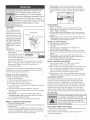
Combustion byproducts produced when
using this product contain chemicals
known to the State of California to cause
cancer, birth defects, or other reproductive
harm.
m
iiiiiiiiiiiiiiiiiiiiiiiiiiiiiiiiiiiiiiiiiiiiiiiiiiiiiiiiiiiiiiii
_FYOU SMELL GAS:
1. Shut off gas suppmy to the
appliance.
2. Extinguish any open flame.
i3. Open _id.
i4. ff odor continues, immediately
call your gas supplier or your
fire department.
Do not store or use gasoline or
other flammable vapors and liquids
in the vicinity of this or any other
appliance.
.An LP cylinder not connected
for use shah not be stored in
the vicinity of this or any other
appmiance.
© Sears, Roebuck and Co. 2

1
For residential use only. Do not use for m
commercial cooking,
1
1
CARBON MONOXIDE HAZARD m
l
Combustion byproducts include carbon m
monoxide which has no odor and can m
cause serious injury or death. Never use m
inside homes, vehicles or tents, m
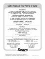
Call Grill Service Center For Help And Parts
if you have questions or need assistance during
assembly, please call 1=800=396=3838. You will be
speaking to a representative of the grill manufacturer
and not a Sears employee. To order new parts call
Sears at 1=800=4=MY=HOME®.
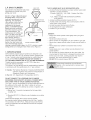
GETTING FAMILmAR WITH YOUR GRILL
Do not use your gritl until you
have read and understood aHthe
information in this manua!, it is
extremely important to be sure that:
• Your grill is properly assembled.
• There are no leaks in the gas supply system
(see 'Leak Testing' section).
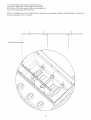
• The burner is properly assembled with the venturi tubes
seated over the valve outlets (Figure 1 below) and there
are no blockages present in the venturi tubes
(see 'Cleaning Venturi Tubes' section).
• Electrical supply cords and/or gas supply hoses are kept
away from any heated surfaces.
• Your grill is positioned in a safe location
(see 'Installation' section).
Figure 1.
• Ensure valve outlets (orifices) are assembled 3/8" (1 cm)
into the venturi tubes.
Check to see that the valve outlets and venturi tubes are
para!lel to the bottom of the base casting of your appliance.
CASTING
Failure to ensure correct ventuti tube
assembly may result in a hazardous fire
or explosion causing serious bodily injury
andfor property damage.
CARING FOR YOUR EQUIPMENT
mNSTALLATION
THE iNSTALLATiON OF THIS APPUANCE MUST
CONFORM WITH LOCAL CODES OR, IN THE
ABSENCE OF LOCAL CODES:
In Canada: must conform to CAN/CGA - B149.2 Propane
Installation Code or CAN/CGA B149.1 Natural Gas
Installatiom
In the U.S.A.: must conform to National Fuel Gas Code
ANSI Z223.1.
When deciding where to place your
appliance, foitow these minimum
clearance distances to adjacent
combustivle materials:
• 24 inches (61 cm) from side of unit (See Figure 2)
18 inches (46 cm) from back of unit (See Figure 2)
FOR YOUR OWN SAFETY:
• Only use your grill OUTDOORS in a well ventilated area
-- preferably 10 feet (3m) from your residence or any
outbuildings.
• Always keep the area around your grill clear of any
combustible materials, gasoline, or other flammable liquids.
• DO NOT operate this grill under overhead or unprotected
construction.
• DO NOT obstruct the
flow of combustion and
ventilation air to the grill.
• DO NOT use in garages,
sheds, breezeways, or
other enclosed areas.
• DO NOT store a spare L.R
(propane) cylinder under or
near your grill
• DO NOT leave your
grill unattended while in
operation.
• DO NOT allow children to
operate or play near your
grill.
MODEL MAYNOTBE EXACTLYAS SHOWN.
DO NOT use while under the influence of alcohol or drugs.
DO NOT insta!l/use in or on recreational vehicles and/or
boats
ELECTRICAL CAUTION
* If any accessory installed on this grill requires an external
electrical power source, it must be electrically grounded in
accordance with local laws or in the absence of !ocal laws,
with the Canadian Electrical Code CSA C22.! or in the U.S.
with the National Electrical Code ANSI-NFPA 70.
, The three-prong plug provides protection against shock
hazard and should be plugged directly into a properly
grounded three-prong receptacle. Do not cut or remove the
grounding prong from this plug.
Ensure all electrical supply cords and fuel supply hoses are
kept well away from any heated surfaces.

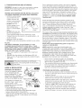
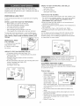
L.P. GAS CYUNDER
Gas cylinders manufactured today have
mechanisms to provide worry free
grilling year round:
Q.C.C.I or Type loQuick Connect
Coupling Valve, ensure fast tank
hook-ups requiring only hand
tightening. The redundant
valve system inhibits the flow
of gas to the burner if the
connection is not correct.
O.RD. or Overfill Protection
Device prevents accidental
gas leaks caused by cylinder
'over-pressurization', the
leading cause of cylinder gas
leaks. The float in the tank
will automatically stop filling at
80% capacity, leaving a
20% area for the expansion
of liquid. Without this safety
feature, the relief valve may FILLING STOPS AT 80%
open and discharge propane,
creating a potential safety hazard. An O.RD. cylinder is easily
distinguished by its triangular hand wheel valve. (Figure 3)
NEW OPD
HANDWHEEL
-2xtematthreads
1. SPECiFiCATIONS
Self-contained propane gas grill systems are designed to be
used only with a 20 Ib (9.1 kg) propane cylinder, equipped with
a Type ! cylinder valve and incorporating an overfill protection
device (O.RD).THE CYUNDER SHOULD NOT EXCEED 18
1/2" (472 MM) iN HEIGHT AND 12 1/2" (3!7 MM) iN DIAMETER.
This gril! cannot be connected to a #510 RO.L type valve
(ones with left-hand threads).
The cylinder for your gas grill must be constructed and marked
in accordance with the specifications of LR gas cylinders:
In Canada: The National Standards of Canada CAN/CSA-B339,
Cylinders, Spheres and Tubes for Transportation of
Dangerous Goods; and Commission.
In the U.S.: U.S. Department of Transportation (D.O.T.)
DO NOT CONNECT TO A PROPANE GAS CYUNDER
EXCEEDING THiS CAPACITY, OR USE A CYLINDER WITH
ANY OTHER TYPE OF VALVE CONNECT!ON DEWCE.
The Type 1 valve is recognizable by the large external thread on
the outlet part of the valve. Non Type 1 valves do not have
these exterior threads. Any attempt to connect a regulator, with
other than the:
i) Mating Type 1 connector (recognized by the large black
coupling nut)
or
ii) Standard #510 P.O.L. fitting, by use of adapters or any other
means,
Could result in damage, fire or iniury and may negate
the important safety features designed into the Type ! system.
The connection of a #5!0 P.O.L. fitting will not provide the flow
control or temperature shut-off features built into the complete
Type 1 System.
THE CYUNDER MUST ALSO BE EQUIPPED WITH:
a. A shut-off valve terminating in a proper cylinder valve outlet
specified in current standards:
• Canada: CAN/CGA - 1.6a - M98 - Outdoor Gas Grills -
Amend. 1.
• U.S.: ANSI Z 21.58a-1998 OUTDOOR COOKING
APPLIANCES.
b. A listed overfilling protection device (O.P.D.).
c. A safety relief valve having direct communication with the
vapor space of the cylinder.
d. A collar to protect the tank shut off valve.
e. An arrangement for vapor withdrawal
f. A bottom ring for mounting.
SAFETY:
• Always turn off the cylinder valve tightly when your grill is
not in use.
• Handle tank valves with care.
• Never connect an unregulated LR gas cylinder to your grill
• Never store a spare cylinder under or near your grill when in
use.
Never subject any cylinder to excessive heat or direct
sunlight.
Always keep your in-use cylinder securely fastened in an
upright position.
• Do not insert any foreign obiects into the valve outlet. You
may damage the back-check. A damaged back-check can
be the source of a leak. Leaking propane may result in
exp!osion, fire, severe personal injury or death.
• DO NOT fill the cylinder beyond 80% full
If the above instructions are not followed
exactly, a fire causing death or serious injury
may occur.

2. TRANSPORTATION AND STORAGE:
WARNING: Although it is safe when used properly, careless
handling of the propane gas cylinder could result in fire,
explosion, and/or serious injury.
PROPANE GAS iS HEAVIER THAN AiR, AND WILL COLLECT mN
LOW AREAS, BNCREASING THE ABOVE RISKS THEREFORE:
* ALWAYS use the cylinder
cap provided with your
cylinder whenever the
cylinder is not connected
to your grill. (Figure 4)
, DO NOT store in a
building, garage or any
other enclosed area.
Store in a we!loventilated CYLINDER RETAINER
area. CAP _ STRAP
* DO NOT store near any
gas burning apparatus or
LP TANK VALVE
in any high-heat areas such as a closed car or trunk.
Transport and store the cylinder in an upright position -- do
not tip on its side.
Store out of reach of children.
• DO NOT smoke while transporting a cylinder in your vehicle.
FILLBNG:
FOR SAFETY REASONS, mFAN OPTIONAL L.R GAS
CYLINDER WAS SUPPLIED W{TN YOUR GRILL, IT HAS
BEEN SNIPPED EMPTY. THE CYLBNDER MUST BE PURGED
OF A_R AND F_LLED PRIOR TO USING ON YOUR GRtLL.
WHEN GETTBNG YOUR CYLINDER FILLED:
* Allow only a qualified UP. gas dealer to fill or repair your
cylinder.
DO NOT allow the cylinder to be filled beyond 80% full.
, Make sure the L.R gas dealer checks the cylinder for leaks
after filling.
If the above instructions are not followed ]
1
exactly, a fire causing death or serious injury
may occur.
HOSE & REGULATOR
PROPANE GAS MODELS:
Your grill is designed to operate REGULATOR
on UP. (propane) gas at a
pressure regulated at 11" water
column(2.74 kPa). A regulator Q.C.C.!
preset to this pressure is supplied
with the grill and MUST be used. REGULATOR
This regulator is equipped with ___
the Q.C.C. Type 1, quick connect
coupling system, which
incorporates the following safety
features: <Figure 51 ___ _"_
• It will not allow gas to flow until a
positive sea! has been made. (Figure 6)
• It has a thermal element that will shut off the flow of gas
between 240 and 300°F (115 and150°C).
• It also has a flow-limiting device which,when activated, will
restrict the flow of gas to 10 cubic feet per hour (0.28 cubic
meters per hour).
Prior to attaching the propane cylinder to the hose and regulator,
be sure the cylinder valve and the appliance valves are OFF. The
cylinder valve is turned off by rotating the handwheel (see Figure 3)
clockwise (left to right) until it stops and all appliance valves should
be in the off position. When attaching the regulator to the cylinder,
make sure that the small probe in the nipple is centered in the
mating Q.C.C. I cylinder valve (see Figure 6). Turn the right hand
threaded Q.C.C.I black nut onto the valve in a clockwise motion
until there is a positive stop. DO NOT USE A WRENCH, HAND
TIGHTEN ONLY.
Should the large black thermally sensitive coupling nut be
exposed to temperatures above 240 and 300°F, it will soften
and allow the regulator probe to disengage from the cylinder
valve -- thereby shutting off the flow of gas. Should this
occur, do not attempt to reconnect the nut. Remove the entire
regulator assembly, and replace it with a new one. (See
'REPLACEMENT PARTS' section in assembly instructions or
contact us at 1-800-396-3838)
The cause of the excessive heat should be determined and
corrected before operating your grill again. The regulator probe
also contains a flow-sensing element, which will limit the flow of
gas to the regulator to a manageable amount (!0 cubic feet per
hour) in the event of a hose or regulator rupture. If it is evident
that the flow control device has been activated, the cause of the
excessive flow should be determined and corrected before using
your grill again.
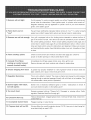
Please refer to the troubleshooting guide on page 29 or
contact us 1-800-396-3838.
NOTE: IMPROPER LIGHTING PROCEDURES CAN
CAUSE THE FLOW CONTROL TO ACTIVATE, RESULTING
IN REDUCED HEAT OUTPUT. IF THIS IS SUSPECTED,
RESET THE FLOW CONTROL BY SHUTTING OFF ALL
BURNER CONTROLS AND THE CYLINDER VALVE. WAIT
30 SECONDS, THEN TURN THE CYLINDER VALVE ON
EXTREMELY SLOWLY - WAIT 5 SECONDS AND TURN THE
BURNER VALVE ON AND LIGHTAS NORMAL.
• Never connect a propane gas grill to an unregulated
propane gas supply or any other gas. Do not attempt to
alter the hose or regulator in any way.
• The connection fitting must be protected when disconnected
from the propane tank. If the fitting is allowed to drag on
the ground, nicks and scratches could occur resulting in a
leak when connected to the propane tank.
PROPANE AND NATURAL GAS MODELS:
Do not allow any grease (or other hot material) to fal! onto
the hose, or allow the hose to come in contact with any hot
surfaces of the grill.
• Visually inspect the entire length of the hose assembly
before each use of the grill. If it is evident there is
excessive abrasion/wear, or the hose is cut, it must be
replaced prior to using your grill. Only the hose assembly
as specified in the Parts List should be used.
Follow the 'LEAK TEST' instructions before lighting your
grill for the first time, every time a propane cylinder is
refilled, if any gas component is changed, if the regulator
flow-limiting device has been activated, after prolonged
periods of storage or non-use or at least once per season.

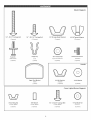
Master Bagpack
114" ° 20 X 2" Carriage Bolt
(6 pieces)
Push Pin
(Side Panet)
(2 pieces)
1t4" - 20 × 3/4" Carriage Bolt
(16 pieces)
S
Binge Clip
(Lid)
(1 piece)
Upper Tank Bracket
(Tank)
(1 piece)
t/4"-20 Large Body Wing Nut
(2 pieces)
t/4"-20 Tapered Wingnut
(22 pieces)
O
318"-16 KnuH Nut
(logo, Heat Indicator)
(2 pieces)
#10=24 Knur_ Screw
(Console)
(2 pieces)
Handle
#10=24 Wing Nut
(Handle)
(2 pieces)
114-314Washer
(2 pieces)
Cross Lighter/Burner Bagpack
#10-24 Wing Nut
(Cross Lighter)
(3 pieces)
Tube Spacer
(Cross Lighter)
(3 pieces)
1/4" - 20 × 314" Carriage Bo_t
(Cross Lighter)
(3 pieces)
C)
tt4"-20 Knurl Nut
(Burners)
(3 pieces)

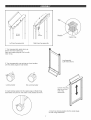
NoTank
Bracket
Left hand leg assembly
Tank
Bracket
Right hand leg assembly
Tab
Not
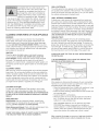
Caster Plug
1. Turn leg assemMy upside down as
shown and insert caster plug.
Make sure caster plug tab is in line with
notch in leg.
2. Turn leg assembly over and tap on a hard surface
until the caster plugs are fully seated.
Leg Assembly
(Left Hand shown)
Locking Caster
Non-Locking Caster
3. Insert locking casters into the caster plugs on front of leg
assemblies and press in until caster is fully seated as shown,
J
Console mounting
tabs are on front
side of leg
assemblies,
4. Insert non-locking casters into the caster plugs
on rear of leg assembiles.

5. Position left hand leg assembly as shown with console mounting tab facing up.
Place nonztank side of bottom pan over bottom support. Attach bottom pan with
1/4"z20 x 3/4" carriage bolt and tapered wing nut.
Console mounting tab facing up.
Bottom Pan
Bottom Support_
Tank opening on right side.
Console mounting tab facing up.
6. Position right hand leg assembly as shown, with console mounting tab facing up.
Place tank side of bottom pan over bottom support. Attach bottom pan with
1/4_20 x 3/4" carriage bolt and tapered wing nut.
114 °20 Tapered Wingnut
1/4" - 20 X 3!4" Carriage Bolt
\
\

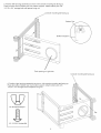
7. Attach console/valve assembly by positioning console over tabs and inserting two #10 knurl screws.
Locate Console on tabs as shown.
(Right side shown)
Mounting Hole
#t0o24 KnuH Screw

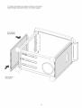
8. Position side panels over legs and slide up into position.
Bottom flange of side panel hooks over bottom support.
Push against
leg assembly
Then slide up
into position
10

9,Positionfrontpanelandfrontpanelstrapintoplace.
insert1/4"-20x2"carriageboltthroughthefourlocationsshown.
Frontpanelstrap
Frontpanel
1/4-20 Tapered Wing Nuts
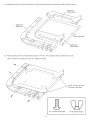
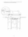
10, Stand the unit onto the casters and attach 4
1/4-20 tapered wing nuts to the four carriage bolts
previously installed. Then align back support with top
rear holes and insert (2) 1/4"-20 x 2" carriage bolts and
fasten with (2) 1/4"-20 wingnuts, Install push
pins into bottom rear holes as shown.
Push Pin
l/4"-20 Tapered Wingnut
1/4" - 20 X 2" Carriage Bolt
Back Support
/
Push Pin
11

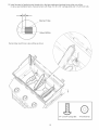
11.Locaterighthandshelf,righthandshelftrim,rightfrontshelfbracket,andrightrearshelfbracketasshown.
Rightrear
shelfbracket
Righthand
shelf
Righthandshelf
Rightfront
shelfbracket
12.Positionpartsasshownandassembleusing(3)1/4"z20x3/4"carriageboltsand taperedwingnuts.
NOTE:inserttabonshelftrimintoholeinsideburnerbase.
Tab
NOTE:Thesetwoholes
notusedinthisstep.
114" o20 X 3/4" Carriage Bo_t 114%20 Tapered Wingnat
12

13.Positionsideburnerbaseassemblyontorightsidemountingbracketasshownin the sequence illustrated below.
Shelf Assembly
Brackets on burner base assembly fit
"inside" mounting bracket.
IMPORTANT: Flange on burner base should go over the flange
on the mounting bracket as shown. Mounting
bracket flange is "sandwiched" between burner base
and burner base brackets
NOTE: Insta!l carriage bolts here first
(front and back) when mounting assembly
to mounting bracket.
Shelf
Shelf Bracket
Mounting Bracket
14. Attach right hand shelf assembly with (4) I/4=20 x 3/4" carriage bolts and four tapered wing nuts, inserting
carriage bolts into mounting bracket assembly first then proceeding to remaining bolts.
Mounting bracket located on leg assembly.
\
15. Repeat attachment procedure described in
steps 13 and 14 for left hand shelf assembly.
1,4" - 20 X 3/4" Carriage Bo_t 114"-20 Tapered Wingnut
13

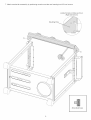
16.Positionbasecastingdownover1/4"z20studsandsecureinplacewithtwo1/4"z20large
bodywingnuts.
I
I
I
I
I
114"-20 Large Body Wing Nut
14

17.Positionbottomcrosslighterassemblyasshown,
beingsuretofeedignitorwiresthroughthefrontholes
inthebottomofthebasecasting.Bottomcross-lighterjust
"lays"looseatthisstageoftheassembly.
NOTE:Crosslightertopandcrosslighterbottomassemblycomepackagedtogetherwiththegrillburners.Theseparts
shouldbeseparatedpriortothisstep.
Leftsideofcrosslighter.
15

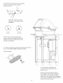
18.installburnersbyfeedingburnerthoughslotinthebasecastingandguidingburnertubeoverorifice
invalve,seeillustrationbelow.Secureburnerswiththree1/4"z20x%4"carriageboltsand1/4"-20Knurlnuts.
Burner Tube
J
Valve Orifice
Burner tube must fit over valve orifice as shown.
\
lf4" - 20 X 3/4" Carriage Bo_t
16

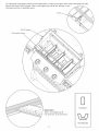
19.Installthreecrosslighterspacersoverthreadedstudsinbottomcrosslighter,theninstallcrosslightertopplate.
Securewiththree#10-24wingnuts.Tabsincrosslightertopmustfitinto"grooves"ontop
ofburnersasshowninillustrationbelow.
#!0-24 Wingnut
Cross Lighter Spacer
IMPORTANT
Tabs in cross lighter top fit
into "grooves" on top of burners.
17
Tube Spacer
#10-24 Wing Nut

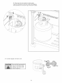
20. install Heat Distribution Plate by placing in position so that the six supports rest on the six ribs in
the base casting.
Suppo_
Rib in Base Casting
18

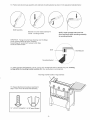
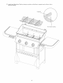
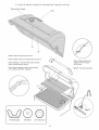
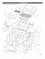
21.InstallLid,Handle,CookingGrid,WarmingRack,HingeClip,andLogo.
TemperatureGauge
Logo
®
Install lid and hinge clip as shown.
Place handle ends into handle tube as shown.
Note: Notches in handle tube mate with tab
inside handle cap as shown.
Then place assembly onto lid and secure
with washers and #10 wingnuts
Note: Keep handle tube
aligned with end caps
at all times.
Tighten wing nuts securely.
twC)
#10-24 Wing Nut #10 Washer
19

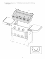
22.Installgreasetrayfromrearofgrillbyslidinggreasetrayinonsupportrailsuntilthe
frontofthetraydropsdownoverthefrontofthesupportrails.
2O
Page is loading ...
Page is loading ...
Page is loading ...
Page is loading ...
Page is loading ...
Page is loading ...
Page is loading ...
Page is loading ...
Page is loading ...
Page is loading ...
Page is loading ...
Page is loading ...
-
 1
1
-
 2
2
-
 3
3
-
 4
4
-
 5
5
-
 6
6
-
 7
7
-
 8
8
-
 9
9
-
 10
10
-
 11
11
-
 12
12
-
 13
13
-
 14
14
-
 15
15
-
 16
16
-
 17
17
-
 18
18
-
 19
19
-
 20
20
-
 21
21
-
 22
22
-
 23
23
-
 24
24
-
 25
25
-
 26
26
-
 27
27
-
 28
28
-
 29
29
-
 30
30
-
 31
31
-
 32
32


Kenmore EEK5539-K401 Owner's manual
- Category
- Barbecues & grills
- Type
- Owner's manual
- This manual is also suitable for
Ask a question and I''ll find the answer in the document
Finding information in a document is now easier with AI
Related papers
-
Fiesta EEK5547-K403 Owner's manual
-
Kenmore 259.16504 Owner's manual
-
-
-
-
-
-
Kenmore Liquid propane gas grill Owner's manual
-
-
Other documents
-
Charbroil 4616238 Owner's manual
-
Bond GSF2616AC Owner's manual
-
-
-
Charbroil 463840604 Owner's manual
-
Alvin Mobile Step-Design File Tube Rack WSF36 User manual
-
-
 BBQ-Pro BQ04024 Owner's manual
-
-
Woods 085-2203-4 Owner's manual
