Descaling Procedure-SteamCraft Ultra and Gemini Series
1. Turn the unit OFF and open the
doors:
This will drain and rinse the generator for about
3 minutes.
2. Turn the unit power back On:
The generator will begin to refill with water.
3. Select Timed with the Timed/Manual
switch:
DO NOT start the timer, since you do not want
to heat the water during descaling. Leave the
doors open.
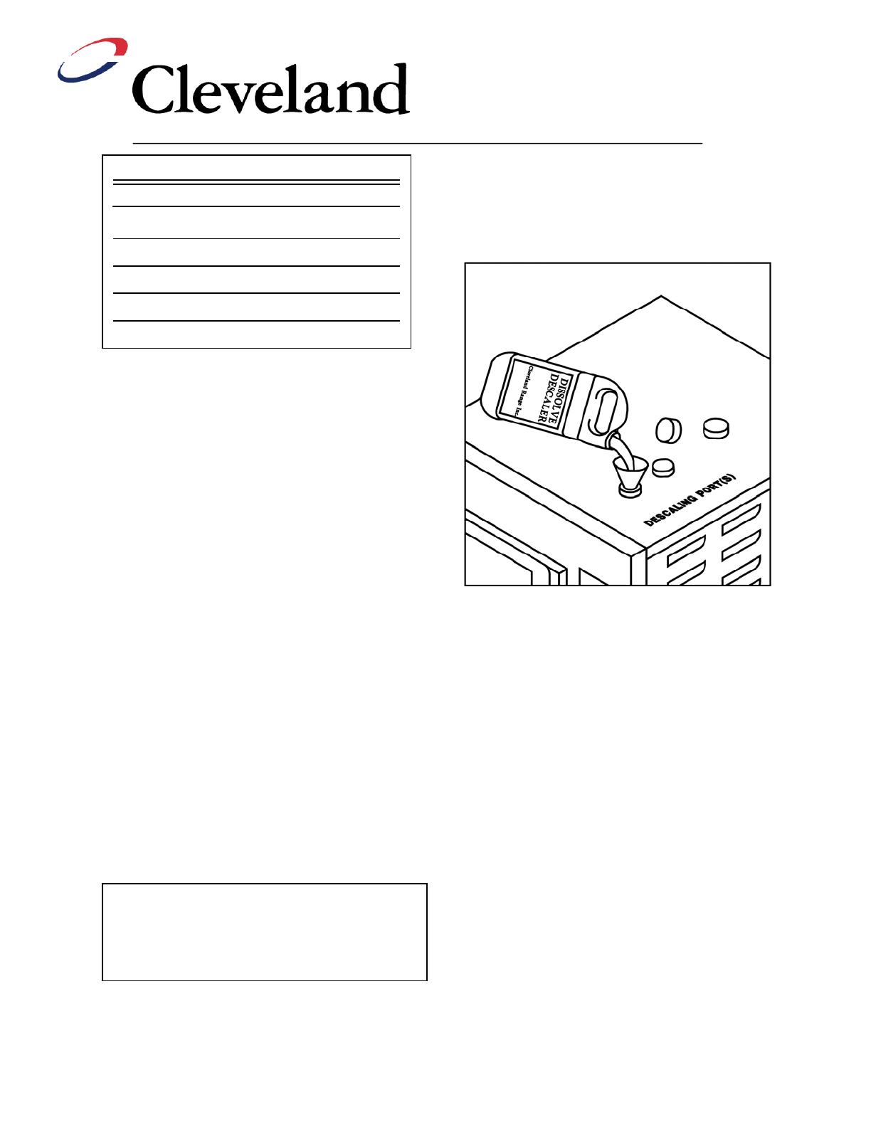
4.
Remove descaling port cap and add
with the specified amount of
DISSLOVE:
(See chart above)
Do this while the unit is refilling. The generators
can take-up to 8 minutes to refill.
5.
After refill has stopped, add extra tap
water into the descaling port until
liquid is seen entering the cooking
cabinet.
Note: Ultra 10 gas will have liquid
coming out of the drain,
Adding extra water when descaling will raise the
descaling solution higher than the normal fill level,
allowing the DISSOLVE to work on sensors and
surfaces above the water line
6. Let the descaler soak in generator for
approximately one hour:
7. After one hour, turn the unit power
Off:
This will drain and rinse the generator
for about 3 minutes.
8. After the 3-minute drain cycle
completes, turn the unit back ON. After
the filling has stopped, add water until
liquid enters the cooking compartment (or
drain for the ultra 10 gas), and then turn
the unit OFF. This will drain and flush any
residue from the water level control
assembly. Replace descaling cap.
9.
After the 3 minute drain cycle
completes, Turn the unit ON and set
the Timer for 20 minutes:
Make sure the
Time/Manual switch is in the timed setting
and the doors are closed.
10. When the timer times out (after 20
minutes) turn the power Off:
This will drain and rinse the generator for
about 3 minutes.
This ends the descaling procedure. You can
now turn the unit back on and resume normal
startup and cooking operations.
How Much DISSOLVE to Use
Model Dissolve
Ultra 3 1/2 Gallon
Ultra 5 1 Gallon
Ultra 10 (Elec.) 1 Gallon (ea.)
Ultra 10 (Gas) 1½ Gallon
Gemini 6 & 10 1 Gallon (ea.)
Note: Some SteamCraft Ultra models (the
electric powered Ultra 10 and Gemini 6 and 10,
for example) have two generators and two
descaling ports. Both units should be descaled
at the same time, using this procedure