Page is loading ...

Refer All Communications to the Nearest
Ingersoll–Rand Office or Distributor.
Ingersoll–Rand Company 2000
Printed in U.S.A.
03539731
Form P7094
Edition 5
October, 2000
OPERATION AND MAINTENANCE MANUAL
FOR SERIES 7A DRILLS
Series 7A Drills are designed for drilling operations in the aerospace, automotive, appliance,
electronic, machining and furniture industries.
Ingersoll–Rand is not responsible for customer modification of tools for applications on which
Ingersoll–Rand was not consulted.
IMPORTANT SAFETY INFORMATION ENCLOSED.
READ THIS MANUAL BEFORE OPERATING TOOL.
IT IS THE RESPONSIBILITY OF THE EMPLOYER TO PLACE THE INFORMATION
IN THIS MANUAL INTO THE HANDS OF THE OPERATOR.
FAILURE TO OBSERVE THE FOLLOWING WARNINGS COULD RESULT IN INJURY.
PLACING TOOL IN SERVICE
• Always operate, inspect and maintain this tool in
accordance with American National Standards
Institute Safety Code for Portable Air Tools
(ANSI B186.1).
• For safety, top performance, and maximum durability
of parts, operate this tool at 90 psig (6.2 bar/620 kPa)
maximum air pressure at the inlet with 5/16” (8 mm)
inside diameter air supply hose.
• Always turn off the air supply and disconnect the air
supply hose before installing, removing or adjusting
any accessory on this tool, or before performing any
maintenance on this tool.
• Do not use damaged, frayed or deteriorated air hoses
and fittings.
• Be sure all hoses and fittings are the correct size and
are tightly secured. See Dwg. TPD905–1 for a typical
piping arrangement.
• Always use clean, dry air at 90 psig maximum air
pressure. Dust, corrosive fumes and/or excessive
moisture can ruin the motor of an air tool.
• Do not lubricate tools with flammable or volatile
liquids such as kerosene, diesel or jet fuel.
• Do not remove any labels. Replace any damaged label.
USING THE TOOL
• Always wear eye protection when operating or
performing maintenance on this tool.
• Always wear hearing protection when operating this
tool.
• Keep hands, loose clothing and long hair away from
rotating end of tool.
• Anticipate and be alert for sudden changes in motion
during start up and operation of any power tool.
• Keep body stance balanced and firm. Do not
overreach when operating this tool. High reaction
torques can occur at or below the recommended air
pressure.
• Tool shaft may continue to rotate briefly after throttle
is released.
• Air powered tools can vibrate in use. Vibration,
repetitive motions or uncomfortable positions may be
harmful to your hands and arms. Stop using any tool
if discomfort, tingling feeling or pain occurs. Seek
medical advice before resuming use.
• Use accessories recommended by Ingersoll–Rand.
• Always use a Dead Handle with Models 7ANST8 and
7AQST8.
• This tool is not designed for working in explosive
atmospheres.
• This tool is not insulated against electric shock.
The use of other than genuine Ingersoll–Rand replacement parts may result in safety hazards, decreased tool performance, and
increased maintenance, and may invalidate all warranties.
Repairs should be made only by authorized trained personnel. Consult your nearest Ingersoll–Rand Authorized Servicenter.
F
E
P
TPD1388

2
WARNING LABEL IDENTIFICATION
FAILURE TO OBSERVE THE FOLLOWING WARNINGS COULD RESULT IN INJURY.
Always wear eye protection
when operating or perform-
ing maintenance on this
tool.
WARNING
WARNING
Always wear hearing
protection when operating
this tool.
Always turn off the air sup-
ply and disconnect the air
supply hose before install-
ing, removing or adjusting
any accessory on this tool,
or before performing any
maintenance on this tool.
WARNING
Air powered tools can vibrate
in use. Vibration, repetitive
motions or uncomfortable po-
sitions may be harmful to your
hands and arms. Stop using
any tool if discomfort, tingling
feeling or pain occurs. Seek
medical advice before resum-
ing use.
WARNING
Do not carry the tool by
the hose.
WARNING
WARNING
Do not use damaged, frayed
or deteriorated air hoses
and fittings.
WARNING
Keep body stance balanced
and firm. Do not overreach
when operating this tool.
WARNING
Operate at 90 psig (6.2 bar/
620 kPa) Maximum air pressure.
90 psig
(6.2bar/620kPa)
PLACING TOOL IN SERVICE
LUBRICATION
Ingersoll–Rand No. 10 Ingersoll–Rand No. 28
Always use an air line lubricator with these tools.
We recommend the following Filter–Lubricator–Regulator
Unit:
For USA – No. C28–04–FKG0–28
For models with D, H, J, JJ, K or L gearing, inject
approximately 6 cc of Ingersoll–Rand No. 28 Grease into the
Grease Fitting in the Gear Case after each 50 000 cycles or
160 hours of operation, whichever occurs first.
For models with M, N or Q gearing, inject approximately
9 cc of Ingersoll–Rand No. 28 Grease into the Grease Fitting
in the Gear Case after each 50 000 cycles or 160 hours of
operation, whichever occurs first.
MAIN LINES 3 TIMES
AIR TOOL INLET SIZE
TO
AIR
SYSTEM
TO
AIR
TOOL
LUBRICATOR
REGULATOR
FILTER
BRANCH LINE 2 TIMES
AIR TOOL INLET SIZE
DRAIN REGULARLY
COMPRESSOR
(Dwg. TPD905–1)

3
HOW TO ORDER A DRILL
DRILL WITH PISTOL GRIP HANDLE
Free Speed Chuck Capacity
Model rpm in Nm
7ADST4 20 000 1/4 6
7AHST4 6 000 1/4 6
7AJST4 4 800 1/4 6
7AJJST4 4 000 1/4 6
7AKST6 3 200 3/8 10
7ALST6 2 400 3/8 10
7AMST6 1 400 3/8 10
7ANST8 900 1/2 13
7AQST8 600 1/2 13

Adressez toutes vos communications au Bureau
Ingersoll–Rand ou distributeur le plus proche.
Ingersoll–Rand Company 2000
Imprimé aux É.U.
MANUEL D’EXPLOITATION ET D’ENTRETIEN
PERCEUSES DE LA SÉRIE 7A
Les perceuses de la Série 7A sont destinées aux opérations de perçage dans les industries de
l’aérospatiale, de l’automobiles, des appareils ménagers, de l’électronique, de l’usinage et des
meubles.
Ingersoll–Rand ne peut être tenu responsable de la modification des outils par le client pour les
adapter à des applications qui n’ont pas été approuvées par Ingersoll–Rand.
ATTENTION
D’IMPORTANTES INFORMATIONS DE SECURITÉ SONT JOINTES.
LIRE CE MANUEL AVANT D’UTILISER L’OUTIL.
L’EMPLOYEUR EST TENU À COMMUNIQUER LES INFORMATIONS
DE CE MANUEL AUX EMPLOYÉS UTILISANT CET OUTIL.
LE NON RESPECT DES AVERTISSEMENTS SUIVANTS PEUT CAUSER DES BLESSURES
MISE EN SERVICE DE L’OUTIL
• Toujours exploiter, inspecter et entretenir cet outil
conformément au Code de sécurité des outils
pneumatiques portatifs de l’American National
Standards Institute (ANSI B186.1).
• Pour la sécurité, les performances optimales et la
durabilité maximale des pièces, cet outil doit être
connecté à une alimentation d’air comprimé de
6,2 bar (620 kPa) maximum à l’entrée, avec un flexible
de 8 mm de diamètre intérieur.
• Couper toujours l’alimentation d’air comprimé et
débrancher le flexible d’alimentation avant d’installer,
déposer ou ajuster tout accessoire sur cet outil, ou
d’entreprendre une opération d’entretien quelconque
sur l’outil.
• Ne pas utiliser des flexibles ou des raccords
endommagés, effilochés ou détériorés.
• S’assurer que tous les flexibles et les raccords sont
correctement dimensionnés et bien serrés. Voir Plan
TPD905–1 pour un exemple type d’agencement des
tuyauteries.
• Utiliser toujours de l’air sec et propre à une pression
maximum de 6,2 bar. La poussière, les fumées
corrosiveset/ou une humidité excessive peuvent
endommager le moteur d’un outil pneumatique.
• Ne jamais lubrifier les outils avec des liquides
inflammables ou volatiles tels que le kérosène, le gasol
ou le carburant d’aviation.
• Ne retirer aucune étiquette. Remplacer toute étiquette
endommagée.
UTILISATION DE L’OUTIL
• Porter toujours des lunettes de protection pendant
l’utilisation et l’entretien de cet outil.
• Porter toujours une protection acoustique pendant
l’utilisation de cet outil.
• Tenir les mains, les vêtements flous et les cheveux
longs, éloignés de l’extrémité rotative de l’outil.
• Prévoir, et ne pas oublier, que tout outil motorisé est
susceptible d’à–coups brusques lors de sa mise en
marche et pendant son utilisation.
• Garder une position équilibrée et ferme. Ne pas se
pencher trop en avant pendant l’utilisation de cet
outil. Des couples de réaction élevés peuvent se
produire à, ou en dessous, de la pression d’air
recommandée.
• La rotation des accessoires de l’outil peut continuer
pendant un certain temps après le relâchement de la
gâchette.
• Les outils pneumatiques peuvent vibrer pendant
l’exploitation. Les vibrations, les mouvements
répétitifs et les positions inconfortables peuvent causer
des douleurs dans les mains et les bras. N’utiliser plus
d’outils en cas d’inconfort, de picotements ou de
douleurs. Consulter un médecin avant de
recommencer à utiliser l’outil.
• Utiliser les accessoires recommandés par
Ingersoll-Rand.
• Utiliser toujours une poignée auxiliaire sur les
Modèles 7ANST–8 et 7AQST8.
• Cet outil n’est pas conçu pour fonctionner dans des
atmosphères explosives.
• Cet outil n’est pas isolé contre les chocs électriques.
NOTE
L’utilisation de rechanges autres que les pièces d’origine Ingersoll–Rand peut causer des risques d’insécurité, réduire les
performances de l’outil et augmenter l’entretien, et peut annuler toutes les garanties.
Les réparations ne doivent être effectuées que par des réparateurs qualifiés autorisés. Consultez votre Centre de Service
Ingersoll–Rand le plus proche.
F

5
SIGNIFICATION DES ETIQUETTES D’AVERTISSEMENT
ATTENTION
LE NON RESPECT DES AVERTISSEMENTS SUIVANTS PEUT CAUSER DES BLESSURES
Porter toujours des lunettes
de protection pendant
l’utilisation et l’entretien de
cet outil.
ATTENTION ATTENTION
Porter toujours une
protection acoustique
pendant l’utilisation de cet
outil.
Les outils pneumatiques
peuvent vibrer pendant
l’exploitation. Les vibrations,
les mouvements répétitifs et les
positions inconfortables
peuvent causer des douleurs
dans les mains et les bras.
N’utiliser plus d’outils en cas
d’inconfort, de picotements ou
de douleurs. Consulter un
médecin avant de recommencer
à utiliser l’outil.
ATTENTION
Ne pas transporter l’outil
par son flexible.
ATTENTION
ATTENTION
Garder une position équilibrée et
ferme. Ne pas se pencher trop
en avant pendant
l’utilisation de cet outil.
ATTENTION
Utiliser de l’air comprimé
à une pression maximum
de 6,2 bar (620 kPa).
90 psig
(6.2bar/620kPa)
Couper toujours l’alimentation
d’air comprimé et débrancher le
flexible d’alimentation avant
d’installer, déposer ou ajuster
tout accessoire sur cet outil, ou
d’entreprendre une opération
d’entretien quelconque sur l’ou-
til.
ATTENTION
ATTENTION
Ne pas utiliser des flexibles ou
des raccords endommageés,
effilochés ou détériorés.
MISE EN SERVICE DE L’OUTIL
LUBRIFICATION
Ingersoll–Rand No. 10 Ingersoll–Rand No. 28
Utiliser toujours un lubrificateur avec ces outils. Nous
recommandons l’emploi du filtre–régulateur–lubrificateur
suivant :
É.U. – No. C28–04–FKG0–28
Pour les modèles équipés de la pignonnerie D, H, J, JJ, K
ou L, injecter environ 6 cm
3
de graisse Ingersoll–Rand No. 28
dans le raccord de graissage du boîtier d’engrenages tous les
50 000 cycles ou au minimum toutes les 160 heures de
fonctionnement.
Pour les modèles équipés de la pignonnerie M, N, ou Q,
injecter environ 9 cm
3
de graisse Ingersoll–Rand No. 28 dans
le raccord de graissage du boîtier d’engrenages tous les 50 000
cycles ou au minimum toutes les 160 heures de
fonctionnement.
TUYAUTERIE PRINCIPALE
AU MOINS 3 FOIS LA DIMEN-
SION DE L’ADMISSION D’AIR
DE L’OUTIL
VERS LE
RÉSEAU D’AIR
COMPRIMÉ
VERS
L’OUTIL
PNEU-
MATIQUE
LUBRIFICATEUR
RÉGULATEUR
FILTRE
LIGNE SECONDAIRE AU
MOINS 2 FOIS LA DIMEN-
SION DE L’ADMISSION
D’AIR DE L’OUTIL
VIDANGER
RÉGULIÈREMENT
COMPRESSEUR
(Plan TPD905–1)

6
MISE EN SERVICE DE L’OUTIL
SPÉCIFICATIONS
Modèle Poignée à
levier
Vitesse libre Capacité du
mandrin
tr/mn pouces (Nm)
7ADST4 pistolet 20 000 1/4 (6)
7AHST4 pistolet 6 000 1/4 (6)
7AJST4 pistolet 4 800 1/4 (6)
7AJJST4 pistolet 4 000 1/4 (6)
7AKST6 pistolet 3 200 3/8 (10)
7ALST6 pistolet 2 400 3/8 (10)
7AMST6 pistolet 1 400 3/8 (10)
7ANST8 pistolet 900 1/2 (13)
7AQST8 pistolet 600 1/2 (13)

Toda comunicación se deberá dirigir a la oficina o al
distribuidor Ingersoll–Rand más próximo.
Ingersoll–Rand Company 2000
Impreso en EE. UU.
MANUAL DE FUNCIONAMIENTO Y MANTENIMIENTO
PARATALADROS MODELOS 7A
NOTA
Los Taladros Modelo 7A están diseñados para las operaciones de taladro en la industria
aeroespacial, del automóvil, electrónica, mecánica y del mueble.
Ingersoll–Rand no aceptará responsabilidad alguna por la modificación de las herramientas
efectuada por el cliente para las aplicaciones que no hayan sido consultadas con
Ingersoll–Rand.
AVISO
SE ADJUNTA INFORMACIÓN IMPORTANTE DE SEGURIDAD.
LEA ESTE MANUAL ANTES DE USAR LA HERRAMIENTA.
ES RESPONSABILIDAD DE LA EMPRESA ASEGURARSE DE QUE EL OPERARIO
ESTÉ AL TANTO DE LA INFORMACIÓN QUE CONTIENE ESTE MANUAL.
EL HACER CASO OMISO DE LOS AVISOS SIGUIENTES PODRÍA OCASIONAR LESIONES.
PARA PONER LA HERRAMIENTA EN
SERVICIO
• Utilice, examine y mantenga siempre esta herramienta
conforme al código de seguridad para herramientas
neumáticas portátiles de la American National
Standards Institute (ANSI B186.1).
• Para seguridad, máximo rendimiento y vida de
servicio de las piezas, use esta herramienta a una
presión de aire máxima de 90 psig (6,2 bar/620 kPa)
en la manguera de suministro de aire con diámetro
interno de 8 mm.
• Corte siempre el suministro de aire y desconecte la
manguera de suministro de aire antes de instalar,
desmontar o ajustar cualquier accesorio de esta
herramienta, o antes de realizar cualquier operación
de mantenimiento de la misma.
• No utilice mangueras de aire y accesorios dañados,
desgastados ni deteriorados.
• Asegúrese de que todas las mangueras y accesorios
sean del tamaño correcto y estén bien apretados. Vea
Esq. TPD905–1 para un típico arreglo de tuberías.
• Use siempre aire limpio y seco a una presión máxima
de 90 psig. El polvo, los gases corrosivos y/o el exceso
de humedad podrían estropear el motor de una
herramienta neumática.
• No lubrique las herramientas con líquidos inflamables
o volátiles tales como queroseno, gasoil o combustible
para motores a reacción.
• No saque ninguna etiqueta. Sustituya toda etiqueta
dañada.
USO DE LA HERRAMIENTA
• Use siempre protección ocular cuando maneje, o
realice operaciones de mantenimiento en esta
herramienta.
• Use siempre protección para los oídos cuando maneje
esta herramienta.
• Mantenga las manos, la ropa suelta y el cabello largo
alejados del extremo giratorio de la herramienta.
• Anticipe y esté alerta sobre los cambios repentinos en
el movimiento durante la puesta en marcha y el
manejo de toda herramienta motorizada.
• Mantenga una postura de cuerpo equilibrada y firme.
No estire demasiado los brazos al manejar la
herramienta. Pueden ocurrir reacciones de alto par a,
o a menos de, la recomendada presión de aire.
• El eje de la herramienta podría seguir girando
brevemente después de haber soltado la palanca de
estrangulación.
• Las herramientas neumáticas pueden vibrar durante
el uso. La vibración, repetición o posiciones incómodas
pueden dañarle los brazos y manos. En caso de
incomodidad, sensación de hormigueo o dolor, deje de
usar la herramienta. Consulte a un médico antes de
volver a usarla otra vez.
• Utilice únicamente los accesorios Ingersoll–Rand
recomendados.
• Use siempre un mango de sujeción con los Modelos
7ANST8 y 7AQST8.
• Esta herramienta no ha sido diseñada para trabajar en
ambientes explosivos.
• Esta herramienta no está aislada contra descargas eléctricas.
NOTA
El uso de piezas de recambio que no sean las auténticas piezas Ingersoll–Rand podría poner en peligro la seguridad, reducir el
rendimiento de la herramienta y aumentar los cuidados de mantenimiento necesarios, así como invalidar toda garantía.
Las reparaciones sólo serán realizadas por personal cualificado y autorizado. Consulte con el centro de servicio Ingersoll–Rand
autorizado más próximo.
E

8
ETIQUETAS DE AVISO
AVISO
EL HACER CASO OMISO DE LOS AVISOS SIGUIENTES PODRÍA OCASIONAR LESIONES.
Usar siempre protección ocular
al manejar o realizar opera-
ciones de mantenimiento en
esta herramienta.
ADVERTENCIA
Usar siempre protección
para los oídos al manejar
esta herramienta.
Las herramientas neumáticas
pueden vibrar durante el uso.
La vibración, los movimientos
repetitivos o las posiciones
incómodas podrían dañarle los
brazos y las manos. En caso
de incomodidad, sensación de
hormigueo o dolor, dejar de
usar la herramienta. Consultar
al médico antes de volver a uti-
lizarla.
No coger la herramienta
por la manguera para le-
vantarla.
ADVERTENCIA
Mantener una postura del cuerpo
equilibrada y firme. No estirar de-
masiado los brazos al manejar la
herramienta.
Manejar la herramienta a una
presión de aire máxima de 90
psig (6,2 bar/620 kPa).
90 psig
(6.2bar/620kPa)
Cortar siempre el suministro
de aire y desconectar la man-
guera de suministro de aire
antes de instalar, retirar o ajus-
tar cualquier accesorio de esta
herramienta, o antes de realizar
cualquier operación de man-
tenimiento de la misma.
No utilizar mangueras de aire
y accesorios dañados, des-
gastados ni deteriorados.
ADVERTENCIA
ADVERTENCIA
ADVERTENCIA
ADVERTENCIA
ADVERTENCIA
ADVERTENCIA
PARA PONER LA HERRAMIENTA EN SERVICIO
LUBRICACIÓN
Ingersoll–Rand Nº 10 Ingersoll–Rand Nº 28
Utilice siempre un lubricador de aire comprimido con estas
herramientas. Recomendamos la siguiente unidad de
Filtro–Lubricador–Regulador:
EE. UU. – Nº C28–04–FKG0–28
Para modelos de engranaje D, H, J, JJ, K o L, después de
cada 50 000 ciclos o 160 horas de funcionamiento (lo que
ocurra primero), inyecte unos 6 cc de Grasa Ingersoll–Rand
Nº 28 en el engrasador de la caja de engranaje.
Para modelos de engranaje M, N o Q, después de cada
50 000 ciclos o 160 horas de funcionamiento (lo que ocurra
primero), inyecte unos 9 cc de Grasa Ingersoll–Rand Nº 28 en
el engrasador de la caja de engranaje.
TUBERÍAS PRINCIPALES 3
VECES EL TAMAÑO DE
ENTRADA DE HERRAMIENTA
NEUMÁTICA
AL SISTEMA
NEUMÁTICO
A LA
HERRA–
MIENTA
NEUMÁTICA
LUBRICADOR
REGULADOR
FILTRO
TUBERÍA DE RAMAL
2 VECES EL TAMAÑO
DE ENTRADA DE
HERRAMIENTA
NEUMÁTICA
PURGAR
PERIÓDICAMENTE
COMPRESOR
(Esq. TPD905–1)

9
PARA PONER LA HERRAMIENTA EN SERVICIO
ESPECIFICACIONES
Modelo Tipo de Mango Velocidad Libre Capacidad de
Portapuntas
rpm pulg. (Nm)
7ADST4 pistola 20 000 1/4 (6)
7AHST4 pistola 6 000 1/4 (6)
7AJST4 pistola 4 800 1/4 (6)
7AJJST4 pistola 4 000 1/4 (6)
7AKST6 pistola 3 200 3/8 (10)
7ALST6 pistola 2 400 3/8 (10)
7AMST6 pistola 1 400 3/8 (10)
7ANST8 pistola 900 1/2 (13)
7AQST8 pistola 600 1/2 (13)

Envie Todos os Comunicados Para o Distribuidor ou
Escritório da Ingersoll–Rand Mais Próximo.
Ingersoll–Rand Company 2000
Impresso nos E.U.A.
MANUAL DE FUNCIONAMENTO E MANUTENÇÃO
BERBEQUINS SÉRIE 7A
AVISO
Os Berbequins7A são concebidos para aplicações de perfuração em linhas de montagem,
indústrias de equipamentos, eletronicas, aeroespaciais e de mobílias.
A Ingersoll–Rand não é responsável por modificações, feitas pelo cliente em ferramentas, nas
quais a Ingersoll–Rand não tenha sido consultada.
ADVERTÊNCIA
INFORMAÇÃO DE SEGURANÇA IMPORTANTE EM ANEXO
LEIA ESTE MANUAL ANTES DE OPERAR A FERRAMENTA.
É DA RESPONSABILIDADE DO EMPREGADOR COLOCAR A INFORMAÇÃO
DESTE MANUAL NAS MÃOS DO OPERADOR.
O NÃO CUMPRIMENTO DAS SEGUINTES ADVERTÊNCIAS PODE RESULTAR EM FERIMENTOS.
COLOCANDO A FERRAMENTA EM
FUNCIONAMENTO
• Sempre opere, inspeccione e mantenha esta
ferramenta de acordo com o Código de Segurança do
Instituto Americano de Padrões Nacionais para
Ferramentas Pneumáticas Portáteis (ANSI B186.1).
• Para segurança, máximo desempenho e máxima
durabilidade das peças, opere esta ferramenta com
uma pressão de ar máxima de 6,2 bar/620 kPa
(90 psig) na entrada da mangueira de alimentação de
ar com diâmetro interno de 8mm (5/16”).
• Desligue sempre a alimentação de ar e desconecte a
mangueira de alimentação de ar antes de instalar,
remover ou ajustar qualquer acessório nesta
ferramenta, ou antes de executar qualquer serviço de
manutenção nesta ferramenta.
• Não use mangueiras de ar ou adaptadores danificados,
gastos ou deteriorados.
• Certifique–se de que todas as mangueiras e
adaptadores sejam do tamanho correcto e estejam
apertados com firmeza. Veja o Desenho TPD905–1
para um arranjo típico de tubagem.
• Use sempre ar seco e limpo com pressão máxima de
90 psig. Pó, fumos corrosivos e/ou humidade excessiva
podem arruinar o motor de uma ferramenta
pneumática.
• Não lubrifique as ferramentas com líquidos
inflamáveis ou voláteis tais como querosene, diesel ou
combustível de jactos.
• Não remova nenhum rótulo. Reponha qualquer rótulo
danificado.
USANDO A FERRAMENTA
• Use sempre óculos de protecção quando estiver
operando ou executando serviço de manutenção nesta
ferramenta.
• Use sempre protecção contra ruído ao operar esta
ferramenta.
• Mantenha as mãos, partes do vestuário soltas e
cabelos compridos afastados da extremidade em
rotação.
• Antecipe e esteja alerta a mudanças repentinas no
movimento quando ligar e operar qualquer
ferramenta motorizada.
• Mantenha a posição do corpo equilibrada e firme. Não
exagere quando operar esta ferramenta. Torques de
reacção elevados podem ocorrer na ou abaixo da
pressão de ar recomendada.
• O eixo da ferramenta pode continuar a girar
brevemente após a pressão tenha sido aliviada.
• Ferramentas accionadas pneumáticamente podem
vibrar em uso. Vibração, movimentos repetitivos ou
posições desconfortáveis podem ser prejudiciais às
mãos e aos braços. Pare de usar a ferramenta caso
ocorra algum desconforto, sensação de formigueiro ou
dor. Procure assistência médica antes de retornar ao
trabalho.
• Use acessórios recomendados pela Ingersoll–Rand.
• Use sempre uma Protecção de Punho com os Modelos
7ANST8 e 7AQST8.
• Esta Ferramenta não foi concebida para trabalhos em
atmosferas explosivas.
• Esta Ferramenta não está isolada contra choques
eléctricos.
AVISO
O uso de peças de substituição que não sejam genuinamente da Ingersoll–Rand podem resultar em riscos de segurança,
diminuição do desempenho da ferramenta, aumento da necessidade de manutenção e pode invalidar todas as garantias.
As reparações devem ser feitas somente por pessoal treinado autorizado. Consulte o Centro de Serviços da Ingersoll–Rand mais
próximo.
P

11
IDENTIFICAÇÃO DO RÓTULO DE ADVERTÊNCIA
ADVERTÊNCIA
O NÃO CUMPRIMENTO DAS SEGUINTES ADVERTÊNCIAS PODE RESULTAR EM FERIMENTO.
Use sempre óculos de pro-
tecção quando estiver ope–
rando ou executando algum
serviço de manutenção nes-
ta ferramenta.
ADVERTÊNCIA
Use sempre protecção contra
o ruído ao operar esta ferra-
menta.
Desligue sempre a alimentação de
ar e desconecte a mangueira de
alimentação de ar antes de insta-
lar, remover ou ajustar qualquer
acessório nesta ferramenta, ou
antes de executar algum serviço
de manutenção nesta ferramenta.
Ferramentas accionadas pneumáti-
camente podem vibrar em uso. Vi-
bração, movimentos repetitivos ou
posições desconfortáveis podem ser
prejudiciais às mãos e aos braços.
Pare de usar a ferramenta caso
ocorra algum desconforto, sen-
sação de formigueiro ou dor . Pro-
cure assistência médica antes de re-
tornar ao trabalho.
ADVERTÊNCIA
Não carregue a ferramenta
segurando na mangueira.
ADVERTÊNCIA
ADVERTÊNCIA
Não use mangueiras de ar ou
adaptadores danificados, gastos
ou deteriorados.
ADVERTÊNCIA
Mantenha a posição do corpo
equilibrada e firme. Não exag-
ere quando operar esta ferra-
menta. Torques de reacção ele-
vados podem ocorrer sob a
pressão de ar recomendada.
ADVERTÊNCIA
Opere com pressão do ar Máxima
de 90–100 psig(6,2–6,9bar).
90 psig
(6.2bar/620kPa)
ADVERTÊNCIA
ADVERTÊNCIA
COLOCANDO A FERRAMENTA EM FUNCIONAMENTO
LUBRIFICAÇÃO
Ingersoll–Rand No. 10 Ingersoll–Rand No. 67
Use sempre um lubrificador de ar de linha com estas
ferramentas. Nós recomendamos a seguinte Unidade
Filtro–Lubrificador–Regulador :
E.U.A. – No. C28–04–FKG0–28
Para modelos com engrenagem D, H, J, JJ, K ou L, injecte
6 cc de Massa Lubrificadora Ingersoll–Rand No 28 na Caixa
de Engrenagens depois de cada 50 000 ciclos ou 160 horas de
operação, qualquer que ocorra primeiro.
Para modelos com engrenagem M, N ou, injecte 9 cc de
Massa Lubrificadora Ingersoll–Rand No 28 na Caixa de
Engrenagens depois de 50 000 ciclos ou 160 horas de
operação, qualquer que ocorra primeiro.
LINHAS PRINCIPAIS 3 VEZES O TAMANHO DA
ENTRADA DA FERRAMENTA PNEUMÁTICA
PARA
SISTEMA DE AR
PARA
FERRAMENTA
PNEUMÁTICA
LUBRIFICADOR
REGULADOR
FILTRO
LINHA RAMIFICADA
2 VEZES O TAMANHO DA
ENTRADA DA FERRA-
MENTA PNEUMÁTICA
DRENE
REGULARMENTE
COMPRESSOR
(Desenho TPD905–1)

12
COLOCANDO A FERRAMENTA EM FUNCIONAMENTO
ESPECIFICAÇÕES
Modelo Tipo de
Punho
Velocidade Livre Capacidade da Bucha
rpm mm (pol.)
7ADST4 pistola 20 000 6 (1/4)
7AHST4 pistola 6 000 6 (1/4)
7AJST4 pistola 4 800 6 (1/4)
7AJJST4 pistola 4 000 6 (1/4)
7AKST6 pistola 3 200 10 (3/8)
7ALST6 pistola 2 400 10 (3/8)
7AMST6 pistola 1 400 10 (3/8)
7ANST8 pistola 900 13 (1/2)
7AQST8 pistola 600 13 (1/2)

MAINTENANCE SECTION
13
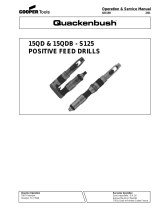
(Dwg. TPA1365–1)

MAINTENANCE SECTION
14
PART NUMBER FOR ORDERING PART NUMBER FOR ORDERING
Motor Housing Assembly ♦ 20 Vane Packet (set of 4 Vanes) . . . . . . . . . . . . 7AH–42A–4
for models ending in EU . . . . . . . . . 7AH–EU–AST40A 21 Cylinder . . . . . . . . . . . . . . . . . . . . . . . . . . . . 7AH–3A
for all other models . . . . . . . . . . . . . 7AH–AST40A 22 Front End Plate . . . . . . . . . . . . . . . . . . . . . . 7AH–11
1 Motor Housing 23 Cylinder Dowel . . . . . . . . . . . . . . . . . . . . . . 7AH–98
for models ending in EU . . . . . . . . . 7AH–EU–BST40A ♦ 24 Front Rotor Bearing . . . . . . . . . . . . . . . . . . . R1–22
for all other models . . . . . . . . . . . . . 7AH–BST40A 25 Front Rotor Bearing Housing . . . . . . . . . . . 7AH–13
* Warning Label 26 Bearing Spring Washer (2) . . . . . . . . . . . . . 7AH–278
for models ending in EU . . . . . . . . . EU–99 27 Bearing Housing Spacer . . . . . . . . . . . . . . . 7AH–81
for all other models . . . . . . . . . . . . . WARNING–7–99 28 Spindle
2 Trigger Bushing . . . . . . . . . . . . . . . . 4RA–91 for D or J ratio . . . . . . . . . . . . . . 7AJ–8A
Trigger Assembly . . . . . . . . . . . . . . . . . 7AH–A93 for H ratio . . . . . . . . . . . . . . . . . 7AH–8
3 Trigger . . . . . . . . . . . . . . . . . . . . . . . 5RA–93 for JJ or Q ratio . . . . . . . . . . . . . 7AQ–8A
4 Trigger Pin . . . . . . . . . . . . . . . . . . . . 7AH–94 for K or N ratio . . . . . . . . . . . . . 7AK–8
♦ 5 Throttle Valve Seat . . . . . . . . . . . . . . . . 7AH–303 for L ratio . . . . . . . . . . . . . . . . . . 7AL–8
♦ 6 Throttle Valve . . . . . . . . . . . . . . . . . . . . 7AH–302 for M ratio . . . . . . . . . . . . . . . . . 7AM–8A
♦ 7 Throttle Valve Spring . . . . . . . . . . . . . . . 7AH–51 29 Spindle Planet Gear Assembly (3)
8 Inlet Bushing Assembly . . . . . . . . . . . . . 7AH–A565 for H ratio (15 teeth) . . . . . . . . . 7AH–A10
♦• 9 Air Strainer Screen . . . . . . . . . . . . . R0A2–61 for J or M ratio
10 Inlet Bushing Spacer . . . . . . . . . . . . . . . 7AH–65 (18 teeth) . . . . . . . . . . . . . . . . . . 7AJ–A10
11 Muffler Assembly . . . . . . . . . . . . . . . . . 3RA–A123 for JJ or Q ratio
♦ 12 Muffler O–ring . . . . . . . . . . . . . . . . . 85H–167 (19 teeth) . . . . . . . . . . . . . . . . . . 7AQ–A10
♦ 13 Muffler Element . . . . . . . . . . . . . . . . . . . 7RA–311 for K or N ratio
• 14 Rear Rotor Bearing Nut . . . . . . . . . . . . . 7AH–105A (21 teeth) . . . . . . . . . . . . . . . . . . 7AK–A10
♦ 15 Rear Rotor Bearing . . . . . . . . . . . . . . . . 7AH–24 for L ratio (22 teeth) . . . . . . . . . 7AL–A10
♦• 16 Rear End Plate Gasket . . . . . . . . . . . . . . . . . 7AH–739 30 Spindle Planet Gear Bearing
17 Rear End Plate . . . . . . . . . . . . . . . . . . . . . . . 7AH–12 (1 for each Gear)
♦• 18 Rear End plate Retainer . . . . . . . . . . . . . . . . 7AH–118 for H ratio . . . . . . . . . . . . . . . . . 7AH–500
19 Rotor for J, JJ, M or Q ratio . . . . . . . . . 7AJ–500
for D, H, J, L, M or N for K, L or N ratio . . . . . . . . . . . 7AK–500
ratio (7 teeth) . . . . . . . . . . . . . . . 7AH–53
for JJ ratio (6 teeth) . . . . . . . . . . 7AJJ–53
for K or Q ratio
(10 teeth) . . . . . . . . . . . . . . . . . . 7AK–53
* Not illustrated.
♦ Indicates Tune–up Kit part.
• To keep downtime to a minimum, it is desirable to have on hand certain repair parts. We recommend that you stock one (pair or set) of each part indicated
by a bullet (•) for every four tools in service.

MAINTENANCE SECTION
15
PART NUMBER FOR ORDERING PART NUMBER FOR ORDERING
31 Rotor Pinion 39 Grease Fitting . . . . . . . . . . . . . . . . . . . . . D0F9–879
for H, M or N ratio (22 teeth) . . . . . 7AH–17
40 Spindle Bearing . . . . . . . . . . . . . . . . . . . . . . 5A–510
for J ratio (16 teeth) . . . . . . . . . . . . . 7AJ–17 41 Spindle Bearing Retainer . . . . . . . . . . . . . . . 7AH–28
for JJ ratio (13 teeth) . . . . . . . . . . . . 7AJJ–17 42 Grease Shield . . . . . . . . . . . . . . . . . . . . . . . . 7AH–701
32 Rotor Pinion Spacer 43 Drill Chuck Spacer . . . . . . . . . . . . . . . . . . . . . 5A–90
for H, J, M or N ratio . . . . . . . . . . . . 7AH–18 44 Drill Chuck
for JJ ratio . . . . . . . . . . . . . . . . . . . . 7AJJ–18 for D, H, J or JJ ratio
33 Drive Plate (for D ratio) . . . . . . . . . . . . . . . . . 7AD–171 (0 to 1/4” [0 to 6 mm]
34 Gear Head capacity) . . . . . . . . . . . . . . . . . . . . . . R00A–99
for M ratio (16 teeth) . . . . . . . . . . . . 7AM–216 for K, L or M ratio (0 to 3/8”
for N ratio (10 teeth) . . . . . . . . . . . . 7AN–216 [0 to 10 mm] capacity) . . . . . . . . . . 6A–99
for Q ratio (13 teeth) . . . . . . . . . . . . 7AQ–216 for N or Q ratio (5/64” to 1/2”
35 Gear Head Planet Gear Assembly (3) [2 to 13 mm] capacity) . . . . . . . . . . R0K–99
for M or N ratio (15 teeth) . . . . . . . . 7AH–A10 * Chuck Key
for Q ratio (21 teeth) . . . . . . . . . . . . 7AP–A10 for R00A–99 chuck . . . . . . . . . . . . . R00A–J253
36 Gear Head Planet Gear Bearing for 6A–99 chuck . . . . . . . . . . . . . . . R0J–J253
(1 for each Gear) (for M, N or Q ratio) . . . . 7AH–500 for R0K–99 chuck . . . . . . . . . . . . . . R1T–J253
37 Gear Head Spacer (for M, N or Q ratio) . . . . . 7AN–80 * Dead Handle Label (for 7ANST8 and
Gear Case Assembly 7AQST8) . . . . . . . . . . . . . . . . . . . . . . . . . . . . . 7AQ–245
for D, H, J, JJ, K or L ratio 45 Dead Handle Adapter (2) . . . . . . . . . . . . . . . . . 7A–49
models ending in ST4 or ST6 . . . . . 7AH–A37A 46 Dead Handle Assembly . . . . . . . . . . . . . . . . . . R1A–A48
for D, H, J, JJ, K or L ratio 47 Pinch Bolt . . . . . . . . . . . . . . . . . . . . . . . . . . 510–638
models ending in EU . . . . . . . . . . . . 7AH–EU–A37A Horizontal Hanger Assembly . . . . . . . . . . . . . 7RA–A366
for M, N or Q ratio models 48 Horizontal Hanger . . . . . . . . . . . . . . . . . . . . 7RA–366
ending in ST6 or ST8 . . . . . . . . . . . . 7AN–A37A 49 Hanger Screw . . . . . . . . . . . . . . . . . . . . . . . . AL–638
for M, N or Q ratio models 50 Vertical Hanger . . . . . . . . . . . . . . . . . . . . . . . . 7L–365
ending in EU . . . . . . . . . . . . . . . . . . . 7AN–EU–A37A * Chuck Shield Kit (for D, H, J,
38 Gear Case JJ or K ratio) . . . . . . . . . . . . . . . . . . . . . . . . . . 7AH–K309
for D, H, J, JJ, K or L ratio models * Warning Label(for N or Q ratio) . . . . . . . . . . . 7A0–245
ending in ST4 or ST6 . . . . . . . . . . . . 7AH–B37A * Tune–up Kit (includes illustrated items 5,
for D, H, J, JJ, K or L ratio 6, 7, 9, 12, 13, 15, 16, 18, 20 and 24) . . . . . . . 7A–DRILLS–TK1
models ending in EU . . . . . . . . . . . . 7AH–EU–B37A
for M, N or Q ratio models ending
in ST6 or ST8 . . . . . . . . . . . . . . . . . . 7AN–B37A
for M, N or Q ratio models
ending in EU . . . . . . . . . . . . . . . . . . 7AN–EU–B37A
* Not illustrated.

16
MAINTENANCE SECTION
Always wear eye protection when operating or
performing maintenance on this tool.
Always turn off the air supply and disconnect the air
supply hose before installing, removing or adjusting
any accessory on this tool, or before performing any
maintenance on this tool.
LUBRICATION
Each time a Series 7A Drill is disassembled for repair or
replacement of parts, lubricate the tool as follows:
1. Moisten all O–rings with O–ring lubricant.
2. Work approximately 1.5 cc of the recommended
grease into the Rear Rotor Bearing (15), Front Rotor
Bearing (24) and the Spindle Bearing (40).
3. Work approximately 6 cc to 8 cc of the recommended
grease into the D, H, J, JJ, K or L ratio gear train and
10 cc to 12 cc of grease into the M, N or Q ratio gear
train. Grease the Planet Gear Bearings (30 and 36),
the gear teeth inside the Gear Case (38) and the planet
gear shafts on the Spindle (28) and Gear Head (34).
DISASSEMBLY
General Instructions
1. Do not disassemble the tool any further than
necessary to replace or repair damaged parts.
2. Whenever grasping a part in a vise, always use
leather–covered or copper–covered vise jaws to
protect the surface of the part and help prevent
distortion. This is particularly true of threaded
members and housings.
3. Do not remove any part which is a press fit in or on a
subassembly unless the removal of that part is
necessary for repairs or replacement.
4. Do not disassemble the tool unless you have a
complete set of new gaskets and O–rings for
replacement.
5. Do not press any needle bearing from a part unless
you have a new needle bearing on hand for
installation. Needle bearings are always damaged
during the removal process.
Disassembly of the Gearing
1. For N or Q ratio, loosen the Pinch Bolt (47) and
remove the Dead Handle Assembly (46) and Handle
Adapter (45).
2. Remove the Drill Chuck (44) by inserting the short
leg of a 1/4” hex key into the Chuck and tightening
the Chuck. Rap the long leg of the key sharply with a
hammer to remove the Chuck.
3. Being careful not to distort the Motor Housing (1),
grasp the flats on the Housing in leather–covered or
copper–covered vise jaws with the Gear Case (38)
facing upward.
4. Using a wrench on the flats of the Gear Case, loosen,
but do not remove the Gear Case.
In the following step, be sure to hold the tool over a
workbench so that you will not drop or lose parts.
5. Remove the tool from the vise and, while holding the
tool horizontally, carefully unscrew the Gear Case and
pull it away from the Motor Housing.
6. For D ratio, hold the Gear Case horizontally and
lightly tap the chuck end of the Spindle (28) with a
plastic hammer to remove the Spindle and Drive
Plate (33).
For H, J, JJ, K or L ratio, hold the Gear Case
horizontally and lightly tap the chuck end of the
Spindle (28) with a plastic hammer to remove the
Spindle and Spindle Planet Gear Assemblies (29).
H, J and JJ ratios have a Rotor Pinion (31) and
Rotor Pinion Spacer (32) that may come out with the
Spindle, or they may have remained with the Rotor
(19) when the Gear Case was withdrawn.
For M, N or Q ratio, hold the Gear Case horizontally
and lightly tap the chuck end of the Spindle (28) with
a plastic hammer to remove the Gear Head (34), Gear
Head Planet Gear Assemblies (35), Gear head Spacer
(37), Spindle and Spindle Planet Gear Assemblies
(29). M and N ratios have a Rotor Pinion (31) and
Rotor Pinion Spacer (32) that may come out with the
Spindle, or they may have remained with the Rotor
(19) when the Gear Case was withdrawn.
7. Withdraw the Spindle Planet Gear Assemblies and/or
Gear Head Planet Gear Assemblies from the Spindle
and/or Gear Head.
8. If it is necessary to remove the Spindle Bearing (40)
from the front of the Gear Case, use a pair of internal
snap ring pliers to remove the Spindle Bearing
Retainer (41). Remove the Bearing Seal (42).
9. Do not remove the Spindle Bearing from the Gear
Case unless it is absolutely necessary and you have
a new Bearing for replacement. If you must remove
the Bearing from the Gear Case, stand the Gear Case
on the table of an arbor press, chuck end upward.
Using a brass rod that will enter the front of the Gear
Case, press the Spindle Bearing from the Gear Case.
10. For H, J, JJ, M or N ratios, if the Rotor Pinion
remained on the Rotor when the Gear Case was
separated from the Housing, Withdraw the Rotor
Pinion along with the Rotor Pinion Spacer.

17
MAINTENANCE SECTION
Disassembly of the Motor
1. Remove the Bearing Housing Spacer (27), Front
Rotor Bearing Housing (25) and the two Bearing
Spring Washers (26) from the Motor Housing (1).
2. Grasp the splined end of the Rotor (19) and pull the
assembled motor from the Motor Housing.
3. Remove the Rear End Plate Gasket (16) from the
Motor Housing.
In the following step, make certain the Rear End
Plate Retainer (18) doesn’t spring away when it is
slipped off the hub of the Rotor.
4. Using a pair of external snap ring pliers and just the
tips of the pliers inserted between the ends of the Rear
End Plate Retainer, spread the Retainer enough to
remove it from the groove in the hub of the Rotor.
5. Withdraw the Rear End Plate (17), Cylinder (21) and
Vanes (20).
6. Check the Front Rotor Bearing (24) for damage or
roughness. If replacement is necessary, support the
Front End Plate (22) between two blocks of wood on
the table of an arbor press and press the Rotor from
the Bearing.
7. Check the Rear Rotor Bearing (15) for damage or
roughness. Do not remove the Rear Rotor Bearing
unless you have a new Bearing on hand for
replacement. The old Bearing will be damaged during
the removal process. To remove the Rear Rotor
Bearing, thread a No. 10–24 x 2” long cap screw,
having at least 1/2” of thread, through the Rear Rotor
Bearing Nut (14) located behind the Bearing. Keep
tightening the screw to jack the Bearing out of the
Housing.
Disassembly of the Pistol Grip Motor Housing
1. Carefully grasp the Motor Housing (1) in
leather–covered or copper–covered vise jaws so that
the handle is upward.
2. Unscrew and remove the Inlet Bushing Assembly (8).
3. Remove the Muffler Assembly (11) and Muffler
O–ring (12) from the Muffler Assembly.
4. Withdraw the Air Strainer Screen (9), Throttle Valve
Spring (7) and Throttle Valve (6) from the housing
handle.
5. Withdraw the Trigger Assembly (3).
6. Remove the Muffler Element (13).
In the following step, only remove the Throttle
Valve Seat (5) when replacing it or when the
Trigger Bushing (2) must be replaced.
7. To remove the Throttle Valve Seat, insert a wire hook
through the central hole of the Seat and hooking the
underside of the Seat, pull the Seat out of the Motor
Housing.
8. Before removing the Trigger Bushing, all Seals and
components must be removed from the Motor
Housing.
a. Reposition the Motor Housing in leather–covered
or copper–covered vise jaws with the Trigger
Bushing upward.
In the following step, apply enough heat to
warm the Housing, but do not exceed 200
degrees Fahrenheit. Do not apply heat directly
to the Skinsulate covering. Take all precautions
necessary to avoid being burned during the
following procedure.
b. Using a torch, apply heat to the Motor Housing
around the Bushing.
c. Thread a 10–32 tap into the Bushing and pull the
Bushing out of the Housing with the tap.
ASSEMBLY
General Instructions
1. Always press on the inner ring of a ball–type bearing
when installing the bearing on a shaft.
2. Always press on the outer ring of a ball–type bearing
when installing the bearing in a bearing recess.
3. Whenever grasping a tool or part in a vise, always use
leather–covered or copper–covered vise jaws. Take
extra care with threaded parts and housings.
4. Except for bearings, always clean every part and wipe
every part with a thin film of oil before installation.
5. Check every bearing for roughness. If an open bearing
must be cleaned, wash it thoroughly in a suitable
cleaning solution and dry with a clean cloth. Sealed
or shielded bearings should never be cleaned.
Work grease thoroughly into every open bearing
before installation.
6. Apply a film of O–ring lubricant to every O–ring
before installation.
7. Unless otherwise noted, always press on the stamped
end of a needle bearing when installing a needle
bearing into a bearing recess. Use a bearing inserting
tool similar to the one shown in Dwg. TPD786.

18
MAINTENANCE SECTION
Needle Bearing Inserting Tool
SHOULDER TO
REGULATE DEPTH
PILOT TO FIT I.D. OF
BEARING.
LENGTH OF PILOT TO BE
APPROXIMATELY 1/8”
LESS THAN LENGTH OF
BEARING
(Dwg. TPD786)
Assembly of the Pistol Grip Motor Housing
1. If the Trigger Bushing (2) was removed, proceed as
follows:
a. Put a few drops of sealant on the end of a thin
stick and insert the stick into the trigger bushing
hole of the Motor Housing (1). Work the stick so
that the Sealant flows against the shoulder inside
the Housing.
b. Insert the Trigger Bushing into the Motor
Housing to a depth approximately one–half
he length of the Bushing.
c. Put a few drops of sealant in the counterbore
surrounding the outside diameter of the Bushing.
d. Rotate the Bushing approximately 180 degrees to
make certain the Sealant makes complete contact
around the outside of the Bushing.
e. Push the Bushing into the Housing until it bottoms
against the shoulder inside the Housing.
f. Allow the Sealant to cure for eight hours at room
temperature.
2. Carefully grasp the Motor Housing in leather–covered
or copper–covered vise jaws, inlet end facing upward.
3. If the Throttle Valve Seat (5) was removed, use a
flat–faced rod 1/2” (13 mm) in diameter by 3”
(76 mm) long to push the Seat into the Motor Housing
until it seats.
4. Press the Trigger (3) onto the grooved end of the
Trigger Pin so that it is at right angles to the hole in
the opposite end of the Pin.
5. Insert the Trigger Assembly into the Trigger Bushing
so that the hole in the Trigger Pin aligns dead center
with the hole in the Throttle Valve Seat.
6. Fold or roll the Muffler Element (13) and work it into
the exhaust cavity in the handle of the Motor
Housing.
7. Using needle nose pliers to hold the short stem end of
the Throttle Valve (6), install the Valve inserting the
long stem end through the hole in the Throttle Valve
and Trigger Pin.
8. Place the Air Strainer Screen (9), closed end first,
inside the large end coil of the Throttle Valve
Spring (7).
9. Insert the Throttle Valve Spring and Screen, small coil
end first, so that the Spring encircles the end of the
Throttle Valve.
10. Apply a thin coat of O–ring lubricant to the Muffler
O–ring (12) and install the O–ring on the hub of the
Muffler (11).
11. Install the Inlet Bushing Spacer (10) in the large hole
in the Muffler Assembly (11).
12. Place the Muffler Assembly on the face of the handle
so that the hub with the Muffler O–ring extends into
the handle.
13. Thread the Air Inlet Bushing (8) into the large hole in
the Muffler Assembly. Tighten the Bushing to a
minimum of 25 ft–lb (34 Nm) torque.
Assembly of the Motor
1. If the Rear Rotor Bearing (15) was removed, install a
new one as follows:
a. Place the Rear Rotor Bearing Nut (14) in the bore
at the bottom of the bearing recess in the Motor
Housing (1).
b. Using a needle bearing inserting tool that has a
pilot extending into the Bearing, and a shoulder
that contacts the the outer radius on the bearing
shell, press the Rear Rotor Bearing, unstamped
end first, into the bearing recess until it is about
0.010” (0.25 mm) below flush.
c. Inject a little grease into the Bearing.
2. Slide the Front End Plate (22), flat side first, over the
splined end of the Rotor (19).
3. Using a sleeve that contacts only the inner ring of
the Front Rotor Bearing (24), press the Front Rotor
Bearing onto the splined hub of the Rotor until it seats
against the Front End Plate.
4. The clearance between the Front End Plate and Rotor
is critical. While holding the Front End Plate, gently
tap the front end of the Rotor until you can insert a
0.001” feeler gauge or shim between the face of the
Rotor and End Plate.

19
MAINTENANCE SECTION
5. Grasp the splined end of the Rotor in leather–covered
or copper–covered vise jaws with the short hub of the
Rotor upward.
6. Wipe each Vane (20) with a film of light oil and place
a Vane in each slot in the Rotor.
7. Place the Cylinder (21), air port end trailing, down
over the Rotor and against the Front End Plate.
8. Place the Rear End Plate (17), flat side first, over the
short hub of the Rotor.
When performing the next step, make certain the
Rear End Plate Retainer (18) does not spring away
as you slip it onto the hub of the Rotor.
9. Install the Rear End Plate Retainer in the groove on
the rotor hub.
10. Smear a film of light grease on the Rear End Plate
Gasket (16) and place the Gasket on the End Plate so
that the port in the Gasket is aligned with the port in
the End Plate.
11. Using an assembly dowel 3/32” in diameter by 10”
long (2.3 mm x 254 mm), align the dowel holes in
the Front End Plate, Cylinder and Rear End Plate.
Insert the assembly rod through the aligned holes so
that about 3” (76 mm) of the rod extends beyond the
Rear End Plate. Insert the extension into the dowel
hole at the bottom of the housing bore, and slide the
motor into the Motor Housing until it seats.
12. Withdraw the assembly dowel and insert the Cylinder
Dowel (23) until the Cylinder Dowel is slightly below
the surface of the Front End Plate.
13. Place the two Bearing Spring Washers (26) inside the
Front Rotor Bearing Housing (25).
14. Slide the Front Rotor Bearing Housing over the Front
Rotor Bearing.
Assembly of the Gearing
1. Using a sleeve that contacts only the outer ring of the
Bearing, press the Spindle Bearing (40) into the Gear
Case (38) until it seats.
2. Place the Grease Shield (42) against the Spindle
Bearing so that the outer rim of the Grease Shield
slides over the outer ring of the Bearing.
3. Using snap ring pliers, install the Spindle Bearing
Retainer (41) in the groove behind the Bearing and
Grease Shield.
4. If the Spindle Planet Gear Bearings (30) or Gear Head
Planet Gear Bearings ((36) were removed, press a
new Bearing into each Spindle Planet Gear (29) or
Gear Head Planet Gear (35) using a bearing inserting
tool that has a pilot and that contacts the outer radius
of the Bearing. Press against the stamped end of the
Bearing.
5. Work a small amount of the recommended grease into
the gear teeth in the Gear Case.
6. Insert the Spindle, threaded end first, into the Gear
Case and through the bore of the Spindle Bearing.
7. For D ratio, align the three holes in the Drive Plate
(33) with the spindle gear shafts and install the Drive
Plate on the shafts.
For all other ratios, grease the bearings and gears of
the Spindle Planet Gear Assemblies (29) and install
them on the pins of the Spindle.
8. For M, N or Q ratio, install the Gear Head Spacer
(37) in the Gear Case against the Spindle Planet
Gears.
9. For M, N or Q ratio, grease the splined hub of the
Gear Head (34) and insert it into the Gear Case. The
splined hub must pass through the Gear Head Spacer
and mesh with the teeth of the Spindle Planet Gears.
10. For M, N or Q ratio, grease the bearings and gears
of the Gear Head Planet Gear Assemblies (35) and
install them on the pins of the Gear Head.
11. For H, J or JJ ratio, grease the Rotor Pinion (31)
and nstall it in the center of the Spindle Planet Gears.
Make certain the teeth of the Pinion and Planet Gears
mesh.
For M or N ratio, grease the Rotor Pinion (31) and
install it in the center of the Gear Head Planet Gears.
Make certain the teeth of the Pinion and Planet Gears
mesh.
12. For H, J, JJ, M or N ratio, slide the Rotor Pinion
Spacer (32) onto the splined shaft of the Rotor.
13. Install the Bearing Housing Spacer (27) against the
gearing or Drive Plate in the Gear Case.
14. Thread the assembled Gear Case onto the assembled
Motor Housing until it is hand tight. Make certain the
gear teeth on the Spindle mesh with the gear teeth of
the Rotor Pinion, Gear Head Planet Gears or Spindle
Planet Gears.
After hand tightening the Gear Case, run the
motor at free speed on low air pressure while final
tightening the Gear Case. Listen while tightening
to make certain the gears mesh properly.
15. Tighten the Gear Case between 40 and 50 ft–lb (54
and 68 Nm) torque.
16. Install the Drill Chuck Spacer (43) onto the drill
spindle.
17. Thread the Drill Chuck (47) onto the drill spindle and
tighten.
18. For M or Q ratio, install the Dead Handle Adapter
(45) and Dead Handle Assembly (46) onto the front
end of the Gear Case. Tighten the Pinch Bolt (47)
between 10 and 20 in. lb (1.4 and 2.3 Nm) torque.

MAINTENANCE SECTION
TROUBLESHOOTING GUIDE
Trouble Probable Cause Solution
Loss of Power Low air pressure Check air supply at the Inlet. For top performance,
the air pressure must be 90 psig (6.2 bar/620 kPa)
at the inlet.
Plugged Air Strainer Screen or
Inlet Screen
Clean the Air Strainer or Screen in a clean,
suitable, cleaning solution. If the Screen cannot be
cleaned, replace it.
Clogged Muffler or Exhaust
Silencer
Clean the Muffler Element in a clean, suitable,
cleaning solution. If it cannot be cleaned, replace
it.
Worn or broken Vanes Replace a complete set of Vanes.
Damaged Rear End Plate Gasket Install a new Rear End Plate Gasket.
Worn or broken Cylinder Replace the Cylinder if it is cracked or if the bore
appears wavy or scored.
Improper lubrication or dirt
build–up
Clean the Motor Unit parts and lubricate them as
instructed.
Leaky Throttle Valve Worn Throttle Valve and/or
Throttle Valve Seat
Install a new Throttle Valve and/or Throttle
Valve Seat.
Dirt accumulation on Throttle
Valve and/or Throttle Valve Seat
Pour about 3 cc of a clean, suitable, cleaning solu-
tion into the air inlet and operate the tool for about
30 seconds. Immediately, pour 3 cc of the recom-
mended oil into the air inlet and operate the tool
for 30 seconds to lubricate all the cleaned parts.
Gear Case gets hot Excessive grease Clean and inspect Gear Case and gearing parts and
lubricate as instructed.
Worn or damaged parts Clean and inspect the Gear Case and Gearing.
Replace worn or broken components.
SAVE THESE INSTRUCTIONS. DO NOT DESTROY.
/