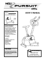
Weslo Pursuit 655s combines advanced engineering and contemporary styling to provide a low-impact workout in the comfort of your own home. Its user-friendly console offers an array of features to track your progress and keep you motivated, including a scan mode that cycles through all of the available workout metrics. With eight levels of resistance and a comfortable, adjustable seat, the Pursuit 655s is perfect for users of all fitness levels. Plus, its compact design and convenient transport wheels make it easy to store and move.
Weslo Pursuit 655s combines advanced engineering and contemporary styling to provide a low-impact workout in the comfort of your own home. Its user-friendly console offers an array of features to track your progress and keep you motivated, including a scan mode that cycles through all of the available workout metrics. With eight levels of resistance and a comfortable, adjustable seat, the Pursuit 655s is perfect for users of all fitness levels. Plus, its compact design and convenient transport wheels make it easy to store and move.


-
 1
1
-
 2
2
-
 3
3
-
 4
4
-
 5
5
-
 6
6
-
 7
7
-
 8
8
-
 9
9
-
 10
10
-
 11
11
-
 12
12
-
 13
13
-
 14
14
-
 15
15
-
 16
16


Weslo Pursuit 655s User manual
- Type
- User manual
- This manual is also suitable for
Weslo Pursuit 655s combines advanced engineering and contemporary styling to provide a low-impact workout in the comfort of your own home. Its user-friendly console offers an array of features to track your progress and keep you motivated, including a scan mode that cycles through all of the available workout metrics. With eight levels of resistance and a comfortable, adjustable seat, the Pursuit 655s is perfect for users of all fitness levels. Plus, its compact design and convenient transport wheels make it easy to store and move.
Ask a question and I''ll find the answer in the document
Finding information in a document is now easier with AI
Related papers
-
Weslo Pursuit 655s User manual
-
-
Weslo WLEVEX29830 User manual
-
-
-
-
-
-
-
Other documents
-
Pro-Form 740EKG PFEVEX2915.0 User manual
-
ProForm WHIRLWIND DUAL ACTION User manual
-
-
-
-
 Noble House 16539 Operating instructions
-
-
-
-
