Modern Forms FR-W1805-120L-BZ Installation guide
- Category
- Household fans
- Type
- Installation guide
This manual is also suitable for

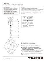
INSTALLATION INSTRUCTIONS
DC
MOTOR
WET
SMART
s
HYDRA
FR-W1805-80L; FR-W1805-96L;
FR-W1805-120L
works with the
Google Assistant
modernforms.com

2FR-W1805
All Modern Forms Smart Fans are:
Durably nished and Rated for
interior and exterior use
WET SMART
Able to coordinate with smart
devices for voice-activated and
thermostat control
Quiet, reliable, and up to 70%
more e cient than AC fans
Wi-Fi and RF enabled for
unlimited control
DC
MOTOR
RF WALL CONTROL
F-WC-WT
Included with each fan
6 Fan speeds
Dims light to 1%
ON/OFF
WIFI TOUCH PANEL
WALL CONTROL
F-TS-BK Black
F-TS-WT White
Sold separately
Full app control
FREE APP DOWNLOAD
Sync with our exclusive Modern Forms
app to control fan speed, use smart
features like Adaptive Learning, create
groups and reduce energy costs
APP INSTRUCTIONS AND SMART HOME DEVICE INTEGRATION
modernforms.com/mfappins
Wet location-listed to the strictest
ETL/cETL safety regulations

3FR-W1805
4.
5.
5.
6.
7.
8.
11.
13.
15.
16.
16.
17.
19.
21.
22.
23.
1 SAFETY RULES..........................................................................................................................................
2 FTC ENERGY GUIDE & SPECIFICATIONS................................................................................................
3 TOOLS AND MATERIALS REQUIRED......................................................................................................
4 PACKAGE CONTENTS..............................................................................................................................
5 MOUNTING OPTIONS.............................................................................................................................
6 HANGING THE FAN..................................................................................................................................
7 MAKING THE ELECTRICAL CONNECTIONS............................................................................................
8 INSTALLING THE WALL CONTROL .........................................................................................................
9 FINISHING THE INSTALLATION...............................................................................................................
10 ATTACHING THE FAN BLADES...............................................................................................................
11 INSTALLING THE ADAPTER PLATE ........................................................................................................
12 INSTALLING THE LED LUMINAIRE MODULE.........................................................................................
13 WALL CONTROL OPERATING INSTRUCTIONS......................................................................................
14 APPLICATION...........................................................................................................................................
15 TROUBLESHOOTING...............................................................................................................................
16 ACCESSORIES...........................................................................................................................................
TABLE OF CONTENTS

4FR-W1805
1. SAFETY RULES
For operation, maintenance, and troubleshooting information,
visit modernforms.com/help.
1. To reduce the risk of electric shock, ensure electricity has been
turned o at the circuit breaker or fuse box before beginning.
2. All wiring must be in accordance with the National Electrical Code
“ANSI/NFPA 70” and local electrical codes. Electrical installation
should be performed by a qualied licensed and insured
electrician.
3. The outlet box and support structure must be securely mounted
and capable of reliably supporting a minimum of 50 lbs (22.7 kg).
Use only UL-listed outlet boxes marked “FOR FAN SUPPORT.”
4. The fan must be mounted with a minimum of 7 ft. (2.1m)
clearance from the trailing edge of the blades to the oor.
5. Avoid placing objects in the path of the blades.
6. To avoid personal injury or damage to the fan and other items,
be cautious when working around or cleaning the fan.
7. Do not use chemicals when cleaning the fan or fan blades.
A dry dust cloth or lightly dampened cloth will be suitable for
most cleaning.
8. After making electrical connections, spliced conductors should be
turned upward and pushed carefully up into the outlet box. The
wires should be spread apart with the grounded conductor and
the equipment-grounding conductor on one side of the outlet
box and ungrounded conductor on the other side of the outlet box.
9. All set screws must be checked and re-tightened where necessary
before installation.
WARNING: To reduce the risk of electric shock, this fan must be
installed with the supplied wall control, or controlled from the Modern
Forms app or wall panel.
WARNING: To reduce the risk of personal injury, do not bend the blade
arms (also referred to as anges), when installing the brackets,
balancing the blades or cleaning the fan.
WARNING: Do not insert foreign objects between rotating fan blades.
WARNING: To reduce the risk of re, electric shock or personal injury,
mount the fan to the outlet box marked acceptable for fan support with
the screws provided with the outlet box.
NOTE: For use only with light kits marked “Suitable for use in wet
locations.” Maximum of 12 fans can operate on a circuit through an
on/o switch or breaker when utilizing the app for the fan control
(without the wall control in the circuit).
NOTE: Maximum of 2 fans can operate on a circuit through the wall
control.

5FR-W1805
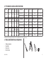
3. TOOLS AND MATERIALS REQUIRED
• Phillips screwdriver
• Step ladder
• Wire cutters
• Electrical tape
FAN FAN SIZE VOLTS N.W
(lbs)
G.W
(lbs)
STANDARD ELECTRICITY AIR FLOW ENERGY COSTS* FAN EFFICACY
Hydra 80” 120 38.92 45.33
High Speed 48W 12428 CFM $13/yr 261.1 CFM/W
Weighted Average 29W 8398 CFM $8/yr 290 CFM/W
FAN FAN SIZE VOLTS N.W
(lbs)
G.W
(lbs)
STANDARD ELECTRICITY AIR FLOW ENERGY COSTS* FAN EFFICACY
Hydra 96” 120 41.5 48.07
High Speed 45W 12950 CFM $13/yr 287.8 CFM/W
Weighted Average 26W 9125 CFM $7/yr 351 CFM/W
FAN FAN SIZE VOLTS N.W
(lbs)
G.W
(lbs)
STANDARD ELECTRICITY AIR FLOW ENERGY COSTS* FAN EFFICACY
Hydra 120” 120 45.95 52.74
High Speed 44W 13300 CFM $12/yr 302.3 CFM/W
Weighted Average 26W 9898 CFM $7/yr 388 CFM/W
*Estimated annual energy cost based on $0.12 per kWh and 6.4 hours use per day.
2. FTC ENERGY GUIDE & SPECIFICATIONS

6FR-W1805
4. PACKAGE CONTENTS
Unpack your fan and check the contents. You should have the following items:
NOTE: ** denotes nish code of fan
M
K
C
A
B
D
E
F
G
H
I
J
L
REF. DESCRIPTION PART NO.
A
Blade Set of 8 (80”)
RPL-F1805-80-BD-**
Blade Set of 8 (96”)
RPL-F1805-96-BD-**
Blade Set of 8 (120”)
RPL-F1805-120-BD-**
B
Hanger Assembly
RPL-F1805-HGR-**
Mounting Bracket
- Downrod Assembly
C
Canopy & Canopy screw cover
RPL-F1805-CAN-**
D
Coupling Cover
RPL-COU-CVR-**
E
Motor Assembly
---
F
Blade Arm Set of 8
G
Adapter Plate
H
LED Module
F6IN-120V-R1-30
I
Glass Shade
RPL-F1805-GLA
J
Luminaire Cover
---
K
Control Receiver W/Hardware (80”)
RPL-F1805-80-REC
Control Receiver W/Hardware (96")
RPL-F1805-96-REC
Control Receiver W/Hardware (120”)
RPL-F1805-120-REC
L
Wall Control W/Hardware
F-WC-WT
M
Hardware Bag
RPL-HYDRA-PARTS
wood screws (2), screws (2),
5/32” lock washers (2), at washers (2), 5.4mm lock washers (2)
5/32” lock washers (2), at washers (2),
W/ Blade Attachment Hardware
screws with at washers and rubber washers (41)

7FR-W1805
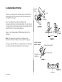
5. MOUNTING OPTIONS
If there isn’t an existing UL/cUL listed mounting box, then read the
following instructions. Disconnect the power by removing fuses or
turning o circuit breakers.
Secure the outlet box directly to the building structure.
Use appropriate fasteners and building materials. The outlet box and
its support must be able to fully support the moving weight of the fan
(at least 50 lbs). Do not use plastic outlet boxes.
Figures 1, 2 and 3 are examples of dierent ways to mount the
outlet box.
NOTE: You may need a longer downrod to maintain proper
blade clearance when installing on a steep, sloped ceiling. (Fig. 3)
To hang your fan where there is an existing xture but no ceiling joist,
you may need an installation hanger bar as shown in (Fig. 4)
FIGURE 1
Outlet box
Outlet box
Outlet box
Provides strong support
Mounting bracket
Recessed
outlet box
SLOPED CEILING
MAX 30° ANGLE
FIGURE 2
FIGURE 4
FIGURE 3
Joist
Support
Brace

8FR-W1805
FIGURE 5
FIGURE 6
FIGURE 7
Mounting
bracket
Screw
Mounting
Bracket
Stop Valve
Screws
Mounting Neck
Screws
Mounting Neck
Stop Bracket
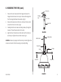
6. HANGING THE FAN
REMEMBER to turn o power at the breaker.
Follow the steps below to hang your fan properly:
1. Disconnect power at the breaker to the fan location. A licensed
electrician must install the fan. (Fig. 5)
2. Remove 1 of 2 screws from the bottom of mounting bracket and
save for use in section 9. Loosen the other screw. (Fig. 6)
3. Unscrew the four mounting neck screws to separate the mount-
ing bracket from the mounting neck. (Fig. 7)
4. Remove stop valve from the neck of the mounting bracket by
loosening the two stop bracket screws on the neck of the mount-
ing bracket in 1/4” from the screw head.

9FR-W1805
6. HANGING THE FAN (cont.)
FIGURE 8
FIGURE 9
Cross pin
Hanger
ball
Downrod
Set screw
1. Take out the set screw located in the hanger ball, lower the
hanger ball and remove the cross pin. Remove the hanger ball
from the hanger ball/downrod assembly. (Fig. 8)
2. Remove the clevis pin and cotter pin, and loosen the two collar
screws from the motor collar. (Fig. 9)
3. Carefully feed the motor wires and safety cable up through the
downrod. Thread the downrod into the collar.
4. Align the holes of downrod and collar and insert the cotter pin
and clevis pin. Tighten the two collar screws. (Fig. 9)
WARNING: Failure to properly install the cotter pin and/or tighten the
screws could result in the fan loosening and possibly falling.
Motor wires
Safety cable
Clevis Pin
Cotter Pin
Downrod
Collar
Screws

10FR-W1805
6. HANGING THE FAN (cont.)
1. Slip the coupling cover, canopy screw cover (painted side face
down), and canopy (opened side up) onto the downrod. (Fig. 10).
Coupling cover goes all the way to the bottom.
2. Carefully reinstall the hanger ball onto the downrod, being sure
that the cross pin is in the correct position, the setscrew is
tightened and wires are not twisted. (Fig. 10)
FIGURE 10
Downrod
Coupling Cover
Motor wires
Canopy
Canopy
screw cover
Safety cable

11FR-W1805
UL/cUL Listed
outlet box
120V Wires
Mounting neck
Mounting neck
screws
Mounting
bracket
Mounting
bracket
Safety
cable
Stop valve
Stop Bracket
screws
Mounting screws
(supplied with
outlet box)
FIGURE 11
FIGURE 12
6. HANGING THE FAN (cont.)
1. Pass the 120-volt supply wires through the center hole in the
ceiling mounting bracket as shown in Fig. 11.
2. Secure the mounting bracket to the ceiling outlet box with the
screws and washers provided with your outlet box. (Fig. 11)
3. Attach mounting neck onto the mounting bracket. Rotate the
mounting neck to align the four screw holes. Secure mounting
neck to the mounting bracket with four mounting neck screws to
become a complete mounting bracket. (Fig. 11)
4. Carefully lift the fan motor assembly up to the mounting bracket
and seat the hanger ball in the mounting bracket. Rotate the
socket assembly until the ball drops and locks into the hanger
bracket screw. (Fig. 12)
5. Secure the safety cable to the building structure using a wood
screw (not included). (Fig. 12)
6. Secure the stop valve onto mounting bracket by tightening two
stop valve screw to close up the opening of mounting bracket.
(Fig. 12)

12FR-W1805
Mounting
bracket
Receiver
FIGURE 13
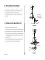
7. MAKING THE ELECTRICAL CONNECTIONS
WARNING: To avoid possible electrical shock, be sure electricity is
turned o at the main fuse box before wiring.
WARNING: Installation of this fan requires that a three-conductor
cable (including ground wire) should run between ceiling and wall
outlet box.
WARNING: Check to see that all connections are tight, including
ground, and that no bare wire is visible at the wire nuts,
except for the ground wire.
Insert the receiver into the mounting bracket with the at side of the
receiver facing the ceiling. (Fig. 13)
Follow the steps below to connect the fan to your household wiring.
Use the plastic wire nuts with your fan. Secure the plastic wire nuts
with electrical tape. Make sure there are no loose strands or
connections.

13FR-W1805
7. MAKING THE ELECTRICAL CONNECTIONS (cont.)
FIGURE 14
White (neutral)
Outlet box
Black (hot)
Black (“AC IN L”)
Red (to motor)
Gray (to motor)
Yellow (to motor)
Yellow (motor)
Gray (motor)
Red (motor)
Receiver
Green (Ground)
To hanger ball
Green (Ground)
To hanger bracket
Green (Ground)
White (for light)
White (for light)
Blue (for light)
Blue (for light)
White (“AC IN N”)
Green (Ground)
Motor to receiver electrical connections: (Fig. 14)
1. Connect the hanger ball/downrod assembly ground wire,
mounting bracket ground wire and receiver ground wire to the
ground wire in outlet box.
WARNING: Failure to connect ground wires could result in poor
fan control functionality.
2. Connect the red wire from the fan to the red wire marked
“TO MOTOR” from the receiver.
3. Connect the gray wire from the fan to the gray wire marked
“TO MOTOR” from the receiver.
4. Connect the yellow wire from the fan to the yellow wire marked
“TO MOTOR” from the receiver.
5. Connect the white wire from the fan to the white wire marked
“For Light” from the receiver.
6. Connect the blue wire from the fan to the blue wire marked
“For Light” from the receiver.
Receiver to house supply wires electrical connections: (Fig. 14)
1. Connect the black (hot) wire from the ceiling to the black wire
marked “AC in L” from the receiver.
2. Connect the white (neutral) from the ceiling to the white wire
marked “AC in N” from the receiver.

14FR-W1805
8. INSTALLING THE WALL CONTROL
FIGURE 15
White White
Red
Black
Green (Ground)
Black (to fan)
Copper
Ground
White
(Neutral)
Black (from Breaker)
Wall control
Wall outlet box
1. Connect ground wires - Important for proper control function.
2. Connect the black wire marked “LINE IN” from the control to the black LINE VOLTAGE wire from the outlet box that
feeds back to the breaker.
3. Connect the red wire from the control to the black wire from the wall outlet box that feeds up to the fan.
4. Connect the white wire from the control to the white (neutral) wire from the wall outlet box.
Wall control to wall outlet box electrical connections: (Fig. 15)
WARNING: Remember to shut the power o at the circuit breaker or fuse box.

15FR-W1805
Wall mounting
plate
Wall outlet box
Wall control
Wall plate
Mounting screws
Mounting screws
FIGURE 16
8. INSTALLING THE WALL CONTROL (cont.)
1. Carefully tuck the wire connections inside the junction box.
Secure the wall control with the two wall control mounting screws
provided. (Fig. 16)
2. Attach the wall mounting plate over the wall control and secure
with the two wall mounting plate screws provided.
3. Fasten the wall plate to the wall mounting plate.
NOTE: Maximum of 2 fans can operate on a circuit through the wall
control.
Maximum of 12 fans can operate on a circuit through an on/o switch
or breaker when utilizing the app for the fan control (without the wall
control in the circuit).

16FR-W1805
FIGURE 17
Screws
Outlet box
Hanger
bracket
Canopy
Canopy screw cover
9. FINISHING THE INSTALLATION
1. Secure all wire connections with supplied wire ties to assist in
canopy installation.
2. Tuck connections neatly into ceiling outlet box.
3. Slide the canopy up to hanger bracket and place the key hole on
the canopy over the screw on the hanger bracket. Turn canopy
until it locks in place at the narrow section of the key holes.
(Fig. 17)
4. Align the circular hole on canopy with the remaining hole on the
hanger bracket. Secure by tightening the one screw previously
loosened and the one previously removed.
5. Adjust the canopy screws as necessary until the canopy and
canopy cover are snug.
WARNING: Make sure tab at bottom of hanger bracket is properly
seated in groove of hanger ball before attaching canopy to bracket.
Failure to properly seat tab in groove could cause damage to electrical
wiring.

17FR-W1805
10. ATTACHING THE FAN BLADES
11. INSTALLING THE ADAPTER PLATE
Screws with
at washers &
rubber washers
Blade arm
Screws
Blade
Mounting ring
Screw
Adapter
plate
1. Attach the blade to the blade arm using the screws with at
washers and rubber washers as shown in Fig. 18.
2. Fasten blade assembly to motor using the screws supplied.
(Fig. 18)
1. Remove one of the three screws from the
mounting ring and loosen the other two screws. (Do not remove.)
2. Place the key holes in the adapter plate over the two screws pre-
viously loosened from the mounting ring. Turn the adapter plate
until the adapter plate locks in place at the narrow section of the
key holes. (Fig. 19)
3. Tighten the two mounting ring screws previously loosened and
the one previously removed to secure adapter plate.
FIGURE 18
FIGURE 19

18FR-W1805
12. INSTALLING THE LED LUMINAIRE MODULE
WARNING: Before starting installation, disconnect the power by turning
o the circuit breaker or removing the fuse at fuse box. Turning power o
using the fan switch is not sucient to prevent electric shock.
NOTE: If you do not plan to install the luminaire module with
your fan at this time, skip to step 5.
1. Remove 1 of the 3 screws from the outer perimeter of the
adapter plate and keep it for future use. Loosen the other 2
screws (Do not remove)
2. Raise and hold the LED luminaire module close to the adapter
plate and proceed to secure the wire connections. Connect the
white wire connector from the luminaire module to the white
wire of the fan. Follow the same procedure with the black wire
connectors. (Fig. 20)
3. Tuck connections neatly into adapter plate. Place the luminaire
module key holes over the 2 screws previously loosened from the
mounting ring, turn luminaire module until it locks in place at the
narrow section of the key holes. Secure by tightening the 2 screws
previously loosened and the one previously removed. (Fig. 20)
4. Raise glass shade up against the luminaire module, and secure it
to fan by turning glass clockwise until snug. Do not over-tighten.
FIGURE 20
Adapter
plate
ScrewsLED Luminaire module
Connection plugs
Glass
shade

19FR-W1805
Adapter
plate
Screws
Glass
shade
INSTALLING THE LED LUMINAIRE MODULE (cont.)
NOTE: Add metal light cover if you do not need lighting function or prefer a
dierent aesthetic. (Fig. 21)
NOTE: Do not connect the LED connector wires if you are using the metal
light cover.
5. If installing the optional metal light cover, make sure it is securely
tightened. (Fig. 21)
FIGURE 21
Metal light cover

20FR-W1805
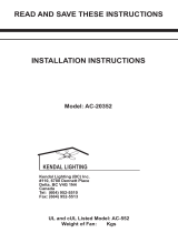
13. WALL CONTROL OPERATING INSTRUCTIONS
Your DC brushless motor is equipped with an intuitive wall control.
Restore power to ceiling fan and test the wall control as below for proper operation.
Button: turn the light ON or OFF
Press/Hold to increase the desired light level.
Press/Hold to decrease the desired light level.
Button: turn the fan ON or OFF
Press/Hold the button to increase the fan speed through
the speed settings.
Press/Hold the button to decrease the fan speed through
the speed settings.
Button: Switch between summer mode and winter mode.
Pairing the Wall Control to Your Fan
Your fan is pre-paired at the factory, NO pairing is necessary.
Wall Control Button Denitions
These seven buttons are used to set the fan speed as follows:
ON-OFF Switch: Pull switch tab to power o in case of emergency. Not necessary for normal fan operation.
FIGURE 22
ON-OFF
switch
Page is loading ...
Page is loading ...
Page is loading ...
Page is loading ...
Page is loading ...
Page is loading ...
Page is loading ...
Page is loading ...
-
 1
1
-
 2
2
-
 3
3
-
 4
4
-
 5
5
-
 6
6
-
 7
7
-
 8
8
-
 9
9
-
 10
10
-
 11
11
-
 12
12
-
 13
13
-
 14
14
-
 15
15
-
 16
16
-
 17
17
-
 18
18
-
 19
19
-
 20
20
-
 21
21
-
 22
22
-
 23
23
-
 24
24
-
 25
25
-
 26
26
-
 27
27
-
 28
28


Modern Forms FR-W1805-120L-BZ Installation guide
- Category
- Household fans
- Type
- Installation guide
- This manual is also suitable for
Ask a question and I''ll find the answer in the document
Finding information in a document is now easier with AI
Related papers
-
Modern Forms FR-W1803-52L-TT Installation guide
-
Modern Forms FR-W1802-38L-TT Installation guide
-
-
Modern Forms FR-W1805 Hydra 80 Installation guide
-
-
-
-
-
-
Other documents
-
 cocoweb ZAMBRANOCF-A-ZA Installation And Operation Instruction Manual
-
Canarm CF52AXI4BN Operating instructions
-
 MATTEO C69201 User manual
-
Savoy 52-417H-3SV-SN Owner's manual
-
 MATTEO C63001 User manual
-
AireRyder FN75539 Instruction For Use & Installation Instructions
-
Hunter Fan 22011 Owner's manual
-
 Designers Choice Collection AC20352-SN Installation guide
-
Home Decorators Collection SW1791 MBK Operating instructions
-


